Table of Contents
Advertisement
Quick Links
Advertisement
Table of Contents

Related Manuals for Asus A7V400-MX/S


Summary of Contents for Asus A7V400-MX/S
- Page 1 A7V400-MX User Guide...
- Page 2 Product warranty or service will not be extended if: (1) the product is repaired, modified or altered, unless such repair, modification of alteration is authorized in writing by ASUS; or (2) the serial number of the product is defaced or missing.
-
Page 3: Table Of Contents
Welcome! ..................1-2 Package contents ................1-2 Special features ................1-2 1.3.1 Product highlights ............1-2 1.3.2 ASUS unique features ............. 1-3 Before you proceed ............... 1-4 Motherboard overview ..............1-5 1.5.1 Motherboard layout ............1-5 1.5.2 Placement direction ............1-6 1.5.3... -
Page 4: Contents
Exit menu ..................2-27 Chapter 3: Software support Installing an operating system ............3-2 Support CD information ..............3-2 3.2.1 Running the support CD ..........3-2 3.2.2 Drivers menu ..............3-3 3.2.3 Utilities menu ..............3-3 3.2.4 ASUS contact information ..........3-4... -
Page 5: Notices
Notices Federal Communications Commission Statement This device complies with FCC Rules Part 15. Operation is subject to the following two conditions: • This device may not cause harmful interference, and • This device must accept any interference received including interference that may cause undesired operation. -
Page 6: Safety Information
Safety information Electrical safety • To prevent electrical shock hazard, disconnect the power cable from the electrical outlet before relocating the system. • When adding or removing devices to or from the system, ensure that the power cables for the devices are unplugged before the signal cables are connected. If possible, disconnect all power cables from the existing system before you add a device. -
Page 7: About This Guide
1. Websites The ASUS websites worldwide provide updated information on ASUS hardware and software products. Refer to the ASUS contact information. 2. Optional documentation Your product package may include optional documentation, such as warranty flyers, that may have been added by your dealer. These documents are not... -
Page 8: A7V400-Mx Specification Summary
A7V400-MX specification summary Socket A for AMD Athlon™XP with speeds up to 2.25+ GHz Thoroughbred/Barton core support Chipset VIA KM400A-A2 VIA VT8235 CE Front Side Bus (FSB) 400/333/266/200 MHz Memory 2 x 184-pin DDR DIMM sockets support up to maximum 2 GB unbuffered PC2700/2100/1600 non-ECC DDR SDRAM memory. - Page 9 Award BIOS Flash Utility Adobe Acrobat Reader ™ Trend Micro PC-cillin 2002 Accessories User Guide ASUS A7V400-MX support CD UltraATA cable FDD cable I/O shield Micro-ATX form factor: 9.6 in x 9.6 in Form Factor * Specifications are subject to change without notice.
-
Page 11: Chapter 1: Product Introduction
Chapter 1 This chapter describes the features of the motherboard. It includes brief descriptions of the motherboard components, and illustrations of the layout, jumper settings, and connectors. Product introduction... -
Page 12: Welcome
Thank you for buying the ASUS ® A7V400-MX motherboard! The ASUS A7V400-MX motherboard comes with the most advanced technologies to deliver maximum performance for Socket A processors. This motherboard comes with value-added features for guaranteed consumer satisfaction. The following sections provide important technical information about the motherboard for future upgrades or system reconfiguration. -
Page 13: Asus Unique Features
ZoomFX, MultiDrive 5.1 and EAX. 1.3.2 ASUS unique features ASUS C.O.P. The ASUS C.O.P. (CPU Overheating Protection) is a hardware protection circuit that automatically shuts down the system power before temperatures go high enough to permanently damage the CPU. See page 2-23. -
Page 14: Before You Proceed
Before you proceed Take note of the following precautions before you install motherboard components or change any motherboard settings. • Unplug the power cord from the wall socket before touching any component. • Use a grounded wrist strap or touch a safely grounded object or to a metal object, such as the power supply case, before handling components to avoid damaging them due to static electricity. -
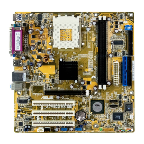
Page 15: Motherboard Overview
CR2032 3V Super Lithium Cell CMOS Power SPDIF CHA_FAN1 PCI3 AD1980 CLRTC CODEC CHASSIS USBPWR56 SB_PWR USBPWR78 FP_AUDIO AUX1 USB56 USB78 GAME PANEL USBPWR34 USBPWR56 CLRTC USBPWR78 Clear CMOS Normal +5VSB (Default) (Default) +5VSB (Default) ASUS A7V400-MX motherboard user guide... -
Page 16: Placement Direction
1.5.2 Placement direction When installing the motherboard to the chassis, make sure to place it in the correct orientation. The edge with external ports goes to the rear part of the chassis as indicated in the image below. It may be more convenient to install major cables, the CPU and modular components before fixing the motherboard inside the case frame. -
Page 17: Central Processing Unit (Cpu)
The CPU should drop easily into place. Do not force the CPU into the socket to avoid bending the pins. If the CPU does not fit, check its alignment and look for bent pins. ASUS A7V400-MX motherboard user guide... -
Page 18: System Memory
You may install single or double-sided 64MB, 128MB, 256MB, 512MB, and 1GB DDR DIMMs to the sockets. For optimum compatibility, it is recommended that you obtain memory modules from qualified vendors. Visit the ASUS website for an updated list of qualified DDR vendors. Chapter 1: Product introduction... -
Page 19: Installing A Dimm
DIMM. Support the DIMM lightly with your fingers when pressing the retaining clips. The DIMM might get damaged when it flips out with extra force. 2. Remove the DIMM from the socket. ASUS A7V400-MX motherboard user guide... -
Page 20: Expansion Slots
Expansion slots In the future, you may need to install expansion cards. The following sub-sections describe the motherboard slots and the expansion cards that they support. Make sure to unplug the power cord before adding or removing expansion cards. Failure to do so may cause you physical injury and damage motherboard components. - Page 21 IRQ assignments for this motherboard PCI slot 1 shared –– –– –– PCI slot 2 –– shared –– –– PCI slot 3 –– –– shared –– AGP slot shared –– –– –– Onboard 1394 –– –– –– shared ASUS A7V400-MX motherboard user guide 1-11...
-
Page 22: Agp Slot
1.8.3 AGP slot The Accelerated Graphics Port (AGP) slot supports +1.5V AGP 4X graphics card. Note the notches on the card golden fingers to ensure that they fit the AGP slot on your motherboard. Install only 1.5V AGP cards on this motherboard! This motherboard does not support 3.3V AGP cards. -
Page 23: Switch And Jumpers
33.33MHz 33.33MHz 33.33MHz ® (Default) A7V400-MX A7V400-MX CPU External Frequency Selection Set the CPU frequency only to the recommended settings. Frequencies other than the recommended CPU bus frequencies are not guaranteed to be stable. ASUS A7V400-MX motherboard user guide 1-13... - Page 24 2. USB device wake-up (3-pin USBPWR34, USBPWR56, USBPWR78) Set these jumpers to +5V to wake up the computer from S1 sleep mode (CPU stopped, DRAM refreshed, system running in low power mode) using the connected USB devices. Set to +5VSB to wake up from S3 sleep mode (no power to CPU, DRAM in slow refresh, power supply in reduced power mode).
- Page 25 5. Plug the power cord and turn ON the computer. 6. Hold down the <Del> key during the boot process and enter BIOS setup to re-enter data. CLRTC ® A7V400-MX Clear CMOS Normal A7V400-MX Clear RTC RAM (Default) ASUS A7V400-MX motherboard user guide 1-15...
-
Page 26: Connectors
1.10 Connectors This section describes and illustrates the rear panel and internal connectors on the motherboard. 1.10.1 Rear panel connectors 1. PS/2 mouse port. This green 6-pin connector is for a PS/2 mouse. 3. Parallel port. This 25-pin port connects a parallel printer, a scanner, or other devices. -
Page 27: Internal Panel Connectors
A7V400-MX Digital Audio Connector • When you input sound for S/PDIF IN, the LINE_OUT will output the sound. Mute LINE_OUT to impede sound output from S/PDIF IN. • The S/PDIF module is purchased separately. ASUS A7V400-MX motherboard user guide 1-17... - Page 28 3. IEEE 1394 connectors (10-1 pin IE1394_1; IE1394_2) These orange connectors support two IEEE 1394 ports via an IEEE 1394 module(s). Connect the IEEE 1394 module 10-1 pin cable to one of these connectors, then mount the IEEE 1394 module to an open slot in the chassis. You may also connect a 1394-compliant internal hard disk to these connectors.
- Page 29 The GAME/MIDI port on the module connects a joystick or a game pad for playing games, and MIDI devices for playing or editing audio files. ® A7V400-MX GAME A7V400-MX Game Connector The USB/GAME module is purchased separately. ASUS A7V400-MX motherboard user guide 1-19...
- Page 30 7. CPU and chassis fan connectors (3-pin CPU_FAN, CHA_FAN) The fan connectors support cooling fans of 350mA ~ 740mA (8.88W max). Connect the fan cables to the fan connectors on the motherboard, making sure that the black wire of each cable matches the ground pin of the connector. CPU_FAN ®...
- Page 31 11. Front panel audio connectors (10-1 pin FP_AUDIO) This is an interface for front panel audio cable that allows convenient connection and control of audio devices. FP_AUDIO ® A7V400-MX A7V400-MX Front Panel Audio Connector ASUS A7V400-MX motherboard user guide 1-21...
- Page 32 12. System panel connector (20-pin PANEL) This connector accommodates several system front panel functions. Speaker Connector Power LED ® Reset SW A7V400-MX IDELED ATX Power SMI Lead Switch* Requires an ATX power supply. A7V400-MX System Panel Connectors • System Power LED Lead (3-1 pin PLED) This 3-1 pin connector connects to the system power LED.
-
Page 33: Chapter 2: Bios Information
Chapter 2 This chapter tells how to change system settings through the BIOS Setup Menus. Detailed descriptions of the BIOS parameters are also provided. BIOS information... -
Page 34: Managing And Updating Your Bios
The following utilities allow you to manage and update the motherboard Basic Input/Output System (BIOS) setup. 1. AwardBIOS Flash Utility (Updates the BIOS in DOS mode using a bootable floppy disk.) 2. ASUS CrashFree BIOS (Updates the BIOS using a floppy disk during POST.) 3. ASUS Update ®... - Page 35 2. At the “A:\” prompt, type “C:\” and then press <Enter>. 3. At the “C:\” prompt, type “AWDFLASH BIOSFILENAME” and then <Enter>. For example: “AWDFLASH aw0702.bin” The AWDFLASH screen appears. 4. Follow steps 4 to 5 of the previous section. ASUS A7V400-MX motherboard user guide...
-
Page 36: Crashfree Bios Feature
VGA, you will not see the screen display when the BIOS crashes even if you reboot the computer. 2.1.4 ASUS Update The ASUS Update is a utility that allows you to update the motherboard BIOS in ® Windows environment. - Page 37 2. Select your desired update method, then click Next. 3. If you selected updating/downloading from the Internet, select the ASUS FTP site nearest you to avoid network traffic, or choose Auto Select. Click Next. 4. From the FTP site, select the BIOS version that you wish to download.
-
Page 38: Bios Beep Codes
BIOS beep codes When you turn the power on and the system runs POST (Power On Self Tests), you will hear BIOS beeps. Refer to the following table for the meaning of the beeps. Award BIOS beep codes Beep Meaning One short beep when No error during POST displaying logo... -
Page 39: Bios Menu Bar
Page Down or – (minus) Scrolls backward through the values for the highlighted field Page Up or + (plus) Scrolls forward through the values for the highlighted field <Enter> Brings up a selection menu for the highlighted field <F10> Saves changes and exit ASUS A7V400-MX motherboard user guide... - Page 40 General help In addition to the Item Help window, the BIOS setup program also provides a General Help screen. You may launch this screen from any menu by simply pressing <F1>. The General Help screen lists the legend keys and their corresponding functions.
-
Page 41: Main Menu
The password is now set to [Set]. This password allows full access to the BIOS Setup menus. To clear the password, highlight this field and press <Enter>. When the same dialog box appear, press <Enter>. The password is set to [Clear]. ASUS A7V400-MX motherboard user guide... - Page 42 A note about passwords The BIOS Setup program allows you to specify passwords in the Main menu. The passwords control access to the BIOS during system startup. Passwords are not case sensitive, meaning, passwords typed in either uppercase or lowercase letters are accepted. The BIOS Setup program allows you to specify two different passwords: a Supervisor password and a User password.
-
Page 43: Ide Primary Master/Slave
Before attempting to configure a hard disk drive, make sure you have the correct configuration information supplied by the drive manufacturer. Incorrect settings may cause the system to fail to recognize the installed hard disk. ASUS A7V400-MX motherboard user guide 2-11... - Page 44 [Manual] & [CHS] Settings IDE Primary Master Select Menu IDE HDD Auto-Detection [Press Enter] Item Specific Help IDE Primary Master [Manual] Press [Enter] to select Access Mode [CHS] sector addressing method. Capacity 40020 MB Cylinder [19158] Head Sector 255] Transfer Mode UDMA 2 : Help ↑↓...
-
Page 45: Advanced Menu
Setting this option to Enabled allows the operating system to determine whether to enable or disable the mouse. Set to Disabled prevents any installed PS/2 mouse from functioning and frees up IRQ 12. Configuration options: [Disabled] [Enabled] ASUS A7V400-MX motherboard user guide 2-13... -
Page 46: Chip Configuration
USB Legacy Support [Enabled] This motherboard supports Universal Serial Bus (USB) devices. When enabled, this item allows the system to detect a USB device at startup. When you set this field to [Disabled], the USB controller legacy mode is disabled whether or not you are using a USB device. - Page 47 This field enables or disables the AGP Fastwrite function. Configuration options: [Disable] [Enabled] AGP Master 1 WS Write [Disabled] Configuration options: [Disable] [Enabled] AGP Master 1 WS Read [Disabled] Configuration options: [Disable] [Enabled] AGP 3.0 Calibration Cycle [Enabled] Configuration options: [Disable] [Enabled] ASUS A7V400-MX motherboard user guide 2-15...
- Page 48 DRAM Clock/Drive Control DRAM Clock/Drive Control Select Menu DRAM Timing [Auto by SPD] Item Specific Help DRAM CAS Latency [2.5] Bank Interleave [Disabled] Pre-charge to Active (Trp) [5T] Active to Precharge (Tras) [7T] Active to CMD (Trcd) [5T] DRAM Burst Length DRAM Command Rate [2T Command] Write Recovery Time...
- Page 49 When set to [Enabled], this feature frees the PCI bus when the CPU is accessing 8-bit ISA cards. This process consumes 50-60 PCI clocks without PCI delayed transaction. Set this field to [Disabled] when using ISA cards that are not PCI 2.2 compliant. Configuration options: [Disabled] [Enabled] ASUS A7V400-MX motherboard user guide 2-17...
- Page 50 VIA OnChip IDE Device VIA OnChip IDE Devices Select Menu IDE DMA Transfer Access [Enabled] Item Specific Help OnChip Pri IDE Controller [Enabled] OnChip Sec IDE Controller [Enabled] Press [Enter] to enable Primary Master [Auto] or disable IDE DMA Primary Slave [Auto] transfer access.
-
Page 51: I/O Device Configuration
EPP Mode Select [EPP1.7] This field sets the EPP mode. The default setting is EPP1.7. This selection is available when you set the Parallel Port Mode to [EPP] or [ECP+EPP]. Configuration options: [EPP1.9] [EPP1.7] ASUS A7V400-MX motherboard user guide 2-19... -
Page 52: Pci Configuration
VIA-3058 AC97 Audio [Auto] This field allows you to enable or disable the onboard AC97 audio controller. Configuration options: [Auto] [Disabled] Onboard LAN [Auto] This field allows you to enable or disable the onboard LAN controller. Configuration options: [Auto] [Disabled] Onboard LAN Boot ROM [Disabled] This field allows you to turn on or off the onboard LAN boot ROM.This item appears only when onboard LAN is enabled. - Page 53 The IRQ Resources sub-menu is activated when the Resources Controlled by parameter is set to [Manual]. Select [PCI Device] to assign an IRQ address to a Plug and Play device. Setting to [Reserved] reserves the IRQ address. Configuration options: [PCI Devices] [Reserved] ASUS A7V400-MX motherboard user guide 2-21...
-
Page 54: Power Menu
Power menu ACPI Suspend Type [S1&S3] Select Menu Power Management [User Define] HDD Power Down [Disabled] Item Specific Help Suspend Mode [Disabled] Video-off Option [Suspend -> Off] Select the ACPI state AC Loss Auto Restart [Auto] used for System Video Off Method [V/H SYNC+Blank] Suspend. -
Page 55: Power Up Control
[V/H SYNC+Blank] [DPMS support] C.O.P. Control [85 degree] Sets the threshold value for the CPU temperature. The ASUS CPU Overheating Protection (C.O.P.) feature of this motherboard automatically shuts down the system when the CPU temperature reaches or exceeds the threshold value. - Page 56 PS2KB Wakeup Select [Hot Key] This parameter allows you to use specific keys on the keyboard to turn on the system. This feature requires an ATX power supply that provides at least 1A on the +5VSB lead. Configuration options: [Disabled] [Ctrl+F1]...[Ctrl+F12] [Power] [Wake] [Any Key] PS2KB Wakeup from S3/S4/S5 [Disabled] When set to [Enabled], this parameter allows you to use the PS/2 keyboard to turn...
-
Page 57: Hardware Monitor
0RPM. Vcore [XX.XX V] +3.3V [XX.XX V] +5V [XX.XX V] +12V [XX.XX V] The onboard hardware monitor automatically detects the voltage output through the onboard voltage regulators. ASUS A7V400-MX motherboard user guide 2-25... -
Page 58: Boot Menu
Boot menu Select Menu First Boot Device [HDD-0] Second Boot Device [CDROM] Item Specific Help Third Boot Device [Floppy] Fourth Boot Device [Disabled] Select your boot device Plug & Play OS [Yes] priority. Reset Configuration Data [Disabled] Quick Power On Self Test [Enabled] Boot Up Floppy Seek [Disabled]... -
Page 59: Exit Menu
Setup menus. When you select this option or if you press <F7>, a confirmation window appears. Select [Yes] to load optimized values. Select Save & Exit or make other changes before saving the values to the non-volatile RAM. ASUS A7V400-MX motherboard user guide 2-27... - Page 60 Discard Changes This option allows you to discard the selections you made and restore the previously saved values. After selecting this option, a confirmation appears. Select [Yes] to discard any changes and load the previously saved values. Save Changes This option saves your selections without exiting the Setup program. You can then return to other menus and make further changes.
-
Page 61: Chapter 3: Software Support
Chapter 3 This chapter describes the contents of the support CD that comes with the motherboard package. Software support... -
Page 62: Installing An Operating System
Installing an operating system This motherboard supports Windows ® 2000/XP operating systems (OS). Always install the latest OS version and corresponding updates so you can maximize the features of your hardware. Because motherboard settings and hardware options vary, use the setup procedures presented in this chapter for general reference only. -
Page 63: Drivers Menu
This convenient utility continuously monitors your computer systems vital components such as fan rotations, CPU temperature, and system voltages, and alerts you on any detected problems. This utility helps you keep your computer at a healthy operating condition. ASUS A7V400-MX motherboard user guide... -
Page 64: Asus Contact Information
Install ASUS Update V5.22.02 The ASUS Update is a utility that allows you to update the motherboard BIOS and drivers. This utility requires an Internet connection either through a network or an Internet Service Provider (ISP). PC-CILLIN 2002 This item installs the PC-cillin 2002 anti-virus program. View the PC-cillin online help for detailed information.