
Related Manuals for HP 8114A


Summary of Contents for HP 8114A
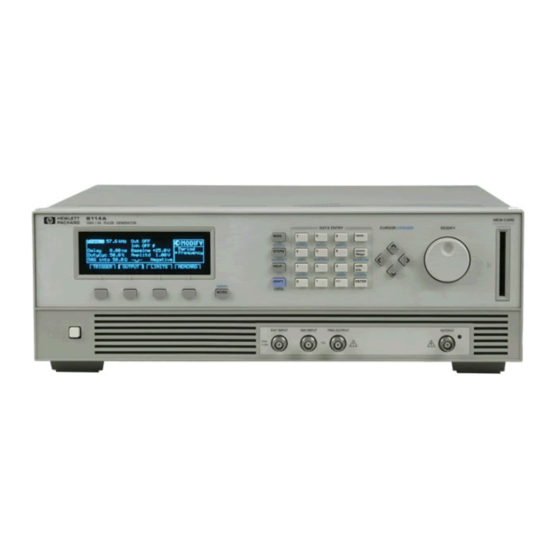
- Page 1 Service Guide HP 8114A 100 V/2 A Programmable Pulse Generator OTS LIBRARY OTS LIBRARY 2 4 0 0 0 1 0 7 4 7 HP Part No. 08114-91021 Printed in Germany December 1994 Edition 1 .O El294...
- Page 2 Notice C o p y r i g h t Safety Symbols Warning Before turning on the instrument, you must connect the protective earth 7 1034 Riiblingen terminal of the instrument to the Federal Repubhc of Germany protective earth conductor of the (mains) Instruction Manual symbols: The power cord.
- Page 3 Notice warranty Limitation of Warranty Certification This Hewlett-Packard product has The foregoing warranty shall not Hewlett-Packard Company a warranty against defects in apply to defects resulting from certifies that this product met its material and workmanship for a improper or inadequate published specifications at the period of one year from date of maintenance by the Buyer,...
- Page 4 Disassembly and Reassembly How to disassemble and reassemble the HP 8114A. Troubleshooting the HP 8114A Techniques for finding the causes of malfunction in the HP 8114A. Replaceable Parts A list of all replaceable parts in the HP 8114A. C L I P The component level information package of the HP 8114A can be obtained separately, and inserted in this section.
-
Page 5: Table Of Contents
EEPROM and RAM Sizes on the PC Boards ..Restoring Default Settings ....Using the HP-IB Device Command ..Overwriting Settings . - Page 6 ..... . Standard HP 8114A (Baseline = 0 V) ..Variable Baseline Option 001 .
- Page 7 2-10 Trigger pulse width ..... . Maximum external voltage ....Transition times Delay from External Input to Trigger Output.
- Page 8 3 . Testing Introduction ..... Conventions IJsed ....
- Page 9 The Tools You Need ....Inside the HP 8114A ....
- Page 10 Variable Baseline (Option 001) ... . . 5-21 HP 8114A Error Messages and Status Register contents . 5-22 Error Messages ....
- Page 11 ....Replacement Boards ....HP 8114A Parts List A. Component Level Information Package Index...
- Page 12 ..4-l. Top View of HP 8114A ....4-2. Removing the Carrying Handles ...
- Page 13 3-40 3-16. Trailing Edge Setting ....5-l. Field Repair Level of HP 8114A Boards ..5-2. Fixed Power Supplies ....
-
Page 15: Replacing The Fuse
Performance Tests in Chapter 3, notify the nearest Hewlett-Packard office. Keep the shipping materials for inspection by the carrier. The HP office will arrange for repair or replacement without awaiting settlement. Power Requirements Caution... -
Page 16: Power Cable
EIP 8114A Service Guide Power Cable In accordance with international safety standards, this instrument, is equipped with a three-wire power cable. When connected to an appropriate AC power receptacle, this cable grounds t,he instrument cabinet. The type of power cable shipped with each instrument, depends on the country of destination. -
Page 17: Rack-Mounting Accessories
Ventilation Requirements The HP 8114A is fitted with two cooling fans. Make sure that there is adequate clearance of 3 inches (75 mm) at the rear and 112 inch (12 mm) at the top and bottom to ensure adequate airflow. If the airflow is restricted the internal operating temperature will be higher, reducing the instrument’s reliability or causing the instrument’s... -
Page 18: Operating Environment
HP 8114A to rain or other excessive moisture. Protect the cause condensation within the instrument. ’ Do not operate the HP 8114A in the presence of flammable gases, fumes or powders. Operation of any electrical instrument in such an environment constitutes a definite safety hazard. -
Page 19: Installing Upgrades
HP 8114A is capable of providing output voltages that may exceed the input capabilities of connected test equipment. The user should ensure t.hat the HP 8114A is operated in a way that prevents damage to connected t,est, equipment. Installing Upgrades ATTENTION! STATIC SENSITIVE DEVICES: You must perform upgrades only in Static Safe work areas. -
Page 20: How To Make A Firmware Update For Hp 8114A
(the card will not fit if inserted the wrong way round) 4. While holding both keys down, switch HP 8114A ON 5. When keys... - Page 21 Ignore the message: Reboot in 2 minutes 10. Extract the Memory Card containing the new firmware 11. Switch ON the HP 8114A 12. The power-on display will now show the new firmware revision and date Installing the HP 8114A l-7...
-
Page 22: Memory Sizes
Memory Sizes The HP 8114A is fitted with the following sizes of memory: EEPROM and RAM Sizes on the PC Boards The following sizes of EEPROM and RAM are fitted to the PC Boards: Timing Board: 16 K Byte EEPROM... -
Page 23: Firmware Upgrade Cards
Firmware upgrades are supplied on a 1 M Byte Memory Card. Memory Card Sizes Memory cards of up to 2 M Byte can be used with the HP 8114A. The following table shows how many setups of a fully-configured Memory Card size No. of setups stored... -
Page 25: Hp 8114A Pulse Generator Specifications
HP 8 114A Pulse Generator Specifications Specifications describe the instrument’s warranted performance. Non-warranted values are described as typical. All specifications apply after a 30 minute warm- up phase with 50 Ohm source impedance into a 50 Ohm load, and are valid from 0°C to 55°C ambient temperature. -
Page 26: Recalibration Period
Recalibration period Warranty Acoustic Noise Pressure Acoustic Noise Pressure For ambient temperature up to SO’C, bis 30°C under normal operation and at the typical operator position: am Arbeitsplatz, normaler Betrleb Measured in accordance with IS0 7779lEN 27779. HP 8114A Pulse Generator... -
Page 27: Declaration Of Conformity
During the measurement against EN 55011, the I/O ports were terminated with their nominal impedance, the HP-IB connector was terminated with the cable HP 10833B. When the product is connected to other devices, the user must ensure that the connecting cables and the other devices are adequately shielded to prevent radiation. -
Page 28: Output
(High-Z) into 5OQ) Warning the output voltage can be dangerous to life. Care should therefore be taken when connecting the HP 8114A to external instruments. When working in HIZ (High-Z) Mode, if you remove the external load the output voltage can be higher than the programmed voltage. -
Page 29: Polarity
Programmable level and duty-cycle limits restrict the available output range to protect the DUT. Pulse Performance Settling time: Transition Times: Measured between 10% and 90% of amplitude, HIZ (High-Z) into 500 ~12 ns (amp1 >lO V) H P 8114A Pulse Generator 2-5... -
Page 30: Pulse Timing
HP 8114A Specifications Pulse Timing Measured at 50% of amplitude Repeatability: factor 4 better than accuracy Can be set as period or frequency Period Range: 66.7 (Frequency: ns to 1.00 Hz to 15.0 MHz) Accuracy: Resolution: 3 digits, best case 100 ps RMS-Jitter: 0.03% + 25 ps (0.05% + 25 ps in the 66.7 ns to 100 ns range) -
Page 31: Duty-Cycle
5052 into 5061. Note that amplitude doubles from HIZ (High-Z) into 508. In double-pulse mode the actual duty-cycle of the signal is twice the value displayed on the HP 8114A screen because two pulses are generated per pulse period. Therefore, the duty-cycle available, and value set, will be limited to half the given by Figure 2-1. -
Page 32: Variable Baseline Option 001
Variable Baseline Option 001 Figure 2-2. Baseline Duty-cycle / Amplitude Ranges Refer to Figure 2-2. Under the following conditions Figure 2-l still applies for the maximum duty-cycle: Positive pulse with negative Baseline -5 V <Baseline i: + 5 V, negative or positive pulses Under the following conditions maximum duty-cycle is 15%: Note also, that the pulse is limited to a SO V window (500 into 5061) so that for positive pulses with positive Baseline, or negative pulses... -
Page 33: Delay
The delay between double pulses can be set as absolute delay or 96 of period. Minimum Period 133.4 Range 20.0 ns to 999 ms (Maximum value: period - width - 4 ns) Accuracy Resolution 3 digits, best case 100 ps Minimum Period 133.4 HP 8114A Pulse Generator Z-9... -
Page 34: Trigger Output
HP 8114A Specifications Trigger Output Level Fixed TTL (2.5 V into 5OC) Output Impedance typical Trigger pulse width 50% of period, typical Maximum external voltage -2 v/+7 v Transition times 5 ns typical Delay from External Input to Trigger Output... - Page 35 Active level (high or low) at the external input or MANual Trigger enables pulses or bursts of pulses. The last pulse or burst of pulses is always completed. External Width Period and width of the output signal are taken from a signal at the External Input. HP 8114A Pulse Generator 2-11...
- Page 36 Instrument settings (350 bytes each) are stored in MS-DOS formatted PCMCIA memorycards. Cards can also be used for convenient firmware updates. Remote Control Operates according to IEEE standard 488.2, 1987 and SCPI 1992.0 Function Code Programming times (All checks and display off) HP 8114A Pulse Generator...
-
Page 37: Testing The Hp 8114A
Testing the HP 8114A Introduction Use the tests in this chapter if you want to check that the HP 8114A 15MHz lOOV/2A Pulse Generator is working correctly. Before starting any testing allow all test equipment to warm up for at least 30 minutes. -
Page 38: Recommended Test Equipment And Accessories
Delay line HP 64008A 22 ns Caution HP 8114A is capable of providing output voltages that may exceed the input capabilities of connected test equipment. The user should ensure that the setting-up instructions in this chapter are followed exactly, to prevent damage to connected test equipment. -
Page 39: 50 0, 10 W Feedthrough Termination
The following parts are required: 1. RI = 53.60, l%, 10 W; HP Part Number: 0699-0146. 2. R2 = 200 0, lo%, 0.5 W, Variable trimmer; HP Part Number: 2 100-3350. R3 = 681 0, l%, 0.5 W; HP Part Number: 0757-0816. -
Page 40: The Product And Serial Number Screen With Variable
Figure 3-2. The Product and Serial Number Screen With Variable Baseline (Option 001) Fitted The contents of the screen are as follows: Timing Board Serial Number Instrument Product Number and Serial Number Variable Baseline Option (001) Serial Number (When this option is fitted) The current Software Revision number Date when the current Software Revision was installed. -
Page 41: Test 1: Period
Procedure 1. On the HP 8114A press TRIGGER and set up page as follows: , ‘-’ .I,j.rjgj,e F;ul.ses 2. On the HP 8114A press OUTPUT and set up page as shown in the following illustration: Configuring the Output Page 3. Connect the HP 8114A to the Counter as follows:... - Page 42 Period Acceptable Range TR entr) 66.7 ns to 70.14 ns 94.9 ns to 106.1 ns 100 ns 600 ns 474.9 ns to 525.1 ns 1 PLS 949.9 ns to 1050.1 ns 1 - 5 5 PS to 5.25 ps 5 0 /is 4 7 .
-
Page 43: Test 2: Width
Connecting FIP 8114A to the Scope . C:ijf.jTI t.JfJ[ll_i::; F’!ji_S& n :jj.r,gj.t+: 3. On the HP 8114A press m and set up UJTPUT page as shown in the following illustration: Configuring the Output Page 4. Set the Digitizing Oscilloscope HP 54121T:... - Page 44 16 ns Check the HP 8114A pulse width at the following settings, repeating step 8 for each width setting made on the HP 8114A: 10. Connect the HP 8114A to the Counter as shown: HP 53.348 COUNXR...
- Page 45 INPUT B 50 s1, negative slope SENSE 12. Set the HP 8114A period to 999 ms 13. Check the HP 8114A width at the following settings: Width Acceptable Range TR Entry 1 / J s 9 4 9 . 5 ns to 1060.6 /Ls 2 - 6 4.76 ps...
-
Page 46: Test 3: Delay
Connecting HP 8114A to the Scope 2. Set the Pulse Generator to: Period Width 100 ns Amplitude Offset output Enable 3. Select the TRIGGER page on the HP 8114A and set up as follows: The TRIGGER Page Set-up Testing the HP 8114A... - Page 47 Set START ON EDGE= POSl and STOP ON EDGE= POS 1 Press the PRECISE EDGE Check the HP 8114A delay at the following settings: Note Record the value of the fixed delay and subtract it from the other readings. Oscilloscope Timebase Delay Acceptable Range 10 nsldiv 0.00 ns...
- Page 48 7. Connect the HP 8114A to the follows: Counter as Connecting HP 8114A to the Counter HP 8114A TRIGGER page select: On the HP 8114A OUTPUT page set: On the to 999 ms FUNCTION I N P U T A...
-
Page 49: Test Specifications
Digitizing Oscilloscope with Accessories Counter Cable, 50 Q, coaxial, BNC Procedure 1. Connect HP 8114A to the Scope as shown: FRONT END HP 8 I ’ 4A UNDtR TEST A D A P T O R Connecting EIP 8114A to the Scope... - Page 50 2. Select the TRIGGER page on the HP 8114A and set up as follows: The TRIGGER Page Set-up illustration: Out ON Inh OFF f Width Configuring the Output Page 4. Set the Digitizing Oscilloscope HP 54121T: Select the Display menu and set the Number of Averages to 32...
- Page 51 PRECISE EDGE FIND setting 6. Check the HP 8114A double delay at the following settings: Double Delay Settings and TR Reference 7. Connect the HP 8114A to the Counter as shown: Connecting HP 8114A to the Counter...
- Page 52 HP 8114A and set up as follows: The TRIGGER Page Set-up following illustration: Configuring the Output Page 11. Check the HP 8114A double pulse delay at the following settings, pressing m to trigger a single cycle each time: Double Delay Settings and TR Reference Acceptable Range...
-
Page 53: Procedure
Power Splitter All cables: 50 0, coaxial, BNC, 122 cm (4 ft) High Power Attenuator Procedure 1. Connect HP 8114A to the Scope as shown: HP 8 I I 4A UNDER TESl Equipment Set-up for Jitter Test Testing the HP 8114A... - Page 54 2. On the HP 8114A press TRIGGER and set up page as follows: . 1: : 1 ; s ). j -( ; I . , 1 I _ ( / {Ii ! _ I ; ; ; F j , J ;- :i; 5 : c ;...
- Page 55 12. The RMS-jitter for period of 100 ns is 75 ps. Enter the result in the Test Report as T R entry 5.1 - 1 13. Set the HP 8114A period to 500 ns 14. Repeat steps 6 to 11 N o t e TIME/DIV = 200 ps/div;...
-
Page 56: Test 5.2: Width Jitter
Digitizing Oscilloscope with Accessories Delay Line (22 ns) Power Splitter All cables 50 0, coaxial, BNC, 122cm (4ft) High Power Attenuator Procedure 1. Connect HP 8114A to the Scope as shown: Equipment Set-up for Jitter Test Testing the HP g114A... - Page 57 2. On the HP 8114A set up the OUTPUT page as shown in the following illustration: Configuring the Output Page 3. Set the Digitizing Oscilloscope HP 54121T: Press Select the Display menu and set the Number of Averages to 128...
- Page 58 13. The RMS-jitter for pulse width of 50 ns is 50 ps. Enter the result in the Test Report as TR entry 5.2 - 1 14. Set the HP 8114A for pulse width of 500ns 15. Repeat steps 7 to 13 Note 16.
-
Page 59: Test 5.3: Delay Jitter
Digitizing Oscilloscope with Accessories All cables: 50 0, coaxial, BNC, 122cm (4ft) High Power Attenuator Procedure 1. Connect HP 8114A to the Scope as shown: HP 54 12 H P 81 l4A UNDER TEST ADAPTOR , A D A P T O R Equipment Set-up for Delay Jitter Test 2. - Page 60 HP 8114A set up the OUTPUT page as shown in the 3. On the following illustration: 1.00 lls Inh OFF f 50.0 I-IS Basclne +0.00 v Width Positive I i n t o Configuring the Output Page 4. Set the Digitizing Oscilloscope HP 54121T:...
-
Page 61: Test 6: Amplitude
Measurement uncertainties need to be calculated out as follows: a) For 5061 into 5061 measurements, the Attenuation Factor must be calculated b) For HIZ (High-Z) into 5061 measurements, the Attenuation Factor, Load impedance, Adjust factor must be calculated. Do these calculations as follows: Testing the HP 6114A 3-25... -
Page 62: A) Calculation For 500 Into 5061 Measurements
Calculation for 503 into 503 measurements Procedure the HP 8114A set up the OUTPUT page as shown in the following illustration: Inh OFF 3 Delay II - Configuring the Output Page 2. Connect HP 8114A to the DVM as shown:... -
Page 63: Equipment Set-Up 2 For Amplitude Test
AD-Converter integration time NPLC: 0.1 (NPLC = Number of Power Line Cycles) 4. Take the reading as VI 5. Connect HP 8114A to the DVM as shown: Figure 3-3. Equipment Set-up 2 for Amplitude Test 6. Take the reading as Vz 7. -
Page 64: B) Calculation For Hiz (High-Z) Into 5062 Measurements
Calculation for FIIZ (High-Z) into 503 measurements Procedure Connecting the Attenuator to the DVM 2. Set the DVM HP 3458A to: Function: 3. %ke the reading as RI 4. %ke the reading for the Coaxial Short, Rz, as shown: SHORT. - Page 65 5. Calculate t.he load impedance: RL = RI - RZJ following illustration: Configuring the Output Page 7. Set the DVM HP 3458A to: Function: Trigger: TRIG EXT NPLC: 8. Connect HP 8114A to the DVM as shown: 9. lhke the reading as V3 Testing the HP 9114A...
- Page 66 10. Connect, HP 8114A to the DVM as shown: 11. ‘l&e the reading as V4 12. Calculate the attenuation factor Gz: = -7...
-
Page 67: Procedure
503) A) Amplitude Test (from 509 Procedure 2. On the HP 8114A set up the UUTPUT page as shown in the following illustration: Configuring the Output Rage 3. Set HP 8114A Delay to 4. ‘kke the baseline reading as B,,a 5. -
Page 68: B) Amplitude Test (From Hiz {High-Z} Into 500)
B) Amplitude Test (from EIIZ {High-Z} into 500) Procedure I. Connect HP 8114A to the DVM as shown: 2. On the HP 8114A set up the CKJTPUT page as shown in the following illustration: Inh OFF f . ..n... Configuring Output Page 3. - Page 69 2.12 v 4.85 V 5.15 v 1 0 v 9.80 v 10.2 v 6 - 9 20 v 19.7 v 20.3 v 60 v 49.4 v 50.6 V 1 0 0 v 98.9 v 101.1 v Testing the HP 8114A 3-33...
-
Page 70: Test 7: Variable Baseline (Option 001)
1. Digitizing Voltmeter (DVM) 2. High Power attenuator 3. 508, O.l%, 1OW Feedthrough Procedure 1. On the HP 8114A set up the OUTPUT page as shown in the following illustration: Configuring the Output Page 2. Connect HP 8114A to the DVM as shown: Equipment Set-up 1 for Variable Baseline Test edings for the following baseline settings (VB). - Page 71 - 2 v -2.125 V -1.876 V - 0 . 1 0 5 v 7 - 6 l o v 7 - 7 7 - K + 4.845 V + 10 v 7 - 9 7 10 Testing the HP 8114A...
-
Page 72: Test 8: Transition Time
Test 8: Transition Time The following tests are required: 2. From HIZ (High-Z) into 50R amplitudes >lO V Test Specifications Range: Equipment Needed Digitizing Oscilloscope with Accessories High Power Attenuator 3.36 Testing the HP 8114A... -
Page 73: Test &La: Leading Edge Test
Test 8.la: Leading Edge Test Leading edge for amplitudes >5 V from 5052 into 5062. Procedure Connecting HP 8114A to the Scope On the HP 8114A press TRIGGER and set up page as follows: following illustration: 500 us Inh OFF f 0.00 r’s Baselne! -
Page 74: Test &Lb: Trailing Edge Test
5. After the averaging, while the oscilloscope is in the Delta t menu, Press the PRECISE EDGE FIND 6. Check the HP 8114A rise time at the following leading edge setting: Test 8.lb: Trailing Edge Test Trailing edge for amplitudes >5 V from 5062 into 500. -
Page 75: Test 8.2A: Leading Edge Test
Test 8.2a: Leading Edge Test Leading edge for amplitudes >lO V from HIZ (High-Z) into 5OQ. Procedure Connecting HP 8114A to the Scope On the HP 8114A press TRIGGER and set up page as follows: n if;j.rj:gi,!a following illustration: Configuring the Output Page... -
Page 76: Test 8.2B: Trailing Edge Test
Select the Timebase menu and set TIME/DIV = 5 ns/div, DELAY = 529 ns 2. After the averaging, while the oscilloscope is in the Delta t menu, Press the PRECISE EDGE FIND 3. Check the HP 8114A output signal falls at the following trailing edge setting: Oscilloscope Delay... -
Page 77: Test 9: Pulse Aberration Test
1. Connect HP 8114A to the Scope as shown: HP 5412 IT FRONT-END HP 8! ’ 4A UNDER TEST Connecting HP 8114A to the Scope On the HP 8114A press TRIGGER and set up page as follows: n il:~:ii$- I W:IIJ; n si!-,sgi;j plJlscs following illustration: Inh OFF f Dut yCyc 50.0 %... -
Page 78: Preshoot
Note lake the oscilloscope’s trace flatness error (GaAs input circuit) into account. 6. Set HP 8114A to: Amplitude = 5 V 7. Repeat steps 3 to 5, but this time set the Scope to: AUTO LEVEL SET OFFSET = 5 V 8. - Page 79 11. Check that Preshoot is within the f5% of amplitude ~50 mV window. 12. Enter the result in the Test Report as TR entry 9 - 3 Testing the HP 8114A 3.43...
-
Page 80: Hp 8114A Performance Test Records
HP 8114A Performance Test Records Test Facility: Report No. Date Customer Tested By Model HP 8114A lOOV/2A Pulse Generator Serial No. Ambient temperature Options Relative humidit,y Firmware Rev. Line frequency Special Notes: Testing the HP 8114A... - Page 81 Test Equipment Used Cal. Due Date Description Model No. Trace No. HP 54121T HP 5334B 2. Counter 4. Digital Voltmeter HP 3458A HP 8112A 3. Pulse Generator HP 54008A 5. Delay Line Testing the HP 8114A...
- Page 82 Serial No. Ambient temperature Relative humidity Customer Line frequency Tested by Date Comments: 3.46 Testing the HP 8114A...
- Page 83 1 - 10 500 ms 475 ms Period Jitter Scope Uncertainty factor TR Entry Test Actual Limit Pass Fail Result Maximum 5.1 - 1 100 ns 75 ps 5.1 - 2 500 ns 175 ps Testing the HP 8114A 3-47...
- Page 84 Width Scope IJncertainty factor Limit Actual Limit Pass Fail TR Entry Test Maximum Minimum Result 2 - l 11.0 ns - ~ 10.0 ns 9.00 ns 2 - 2 50.0 ns 47.0 ns 53.0 ns - - 1 0 5 . 5 n s - - 2 - 3 100 ns 94.5 ns 2 - 4...
- Page 85 50 ms 47.5 ms 52.5 ms 500ms 475 ms Delay Jitter Scope Uncertainty factor Limit Pass Fhil TR Entry Test Actual Maximum Result 50 ps 5.3 - 1 50 ns 175 ps 5.3 - 2 500 ns Testing the HP 9114A...
- Page 86 Double Pulse Delay Scope Uncertainty factor TR Entry Test Limit Actual Limit Pass Fhil Minimum Result Maximum 2 0 . 0 ns 18.75 ns 21.25 ns 52.75 4 - 2 5 0 . 0 ns 47.25 ns ns - - 9 4 .
- Page 87 6 - 10 20 v ____- 19.7 v 20.3 V 6 11 5 o v ___- 49.4 v 5 0 . 6 V _ _ _ _ 6 - 12 100 V’ - 98.9 V 101.1 v Testing the HP 8114A 3-51...
- Page 88 Variable Baseline (Option 001) Note This test is only to be performed if Option 001 is installed. Variable Baseline TR Entry Test Measured Calculated Baseline limits Pass Fhil -25 V -25.355 V -24.645 V ~ - 7 - 2 -20 v -20.305 V -19.695 V - - -10 v -10.205 V...
- Page 89 Leading Edge for Amplitudes >lO V from HIZ (High-Z) into 503 TR Entry Test Actual Limit Pass Rail Result Maximum Leading Trailing Edge for Amplitudes >lO V from HIZ (High-Z) into 5OfI TR Entry Test Limit Actual Pass Fail Result Maximum Trailing Testing the HP 8114A 3 - 5 3...
- Page 90 HP 8114A Service Guide Overshoot and Ringing Scope Uncertainty factor TR Entry Test Acceptable range Pass 25 V &5% of ampl. k5OmV - 9 - 2 5 V 315% of ampl. *50mV - Preshoot TR Entry Test Acceptable range Pass 0 V 3~5% of ampl.
-
Page 91: Disassembly And Reassembly
Disassembly and Reassembly This chapter enables you to disassemble the HP 8114A 15MHz lOOV/2A Pulse Generator down to the levels necessary for removal and replacement of faulty subassemblies. Some of the subassemblies need to be removed in a specific order, and the instructions have been written with this in mind. -
Page 92: Terms Used And What They Mean
The Tools You Need The following tools enable all fixings to be removed and replaced: Small cruciform screwdriver (PC boards, etc) 7mm diameter nut driver (HP-IB cable) strips) 4.2 Disassembly and Reassembly... -
Page 93: Inside The Hp 8114A
BOARD OUTPUT FROM PANEL Figure 4-1. Top View of HP 8114A There is direct access to the Timing board, and the output board. Access to the microprocessor board is possible when the power supply slide is removed. On the power supply slide, the power supply unit, power supply fan, and the optional variable baseline is mounted. -
Page 94: Instructions For Replacing Or Retrofitting Hp 8114A Subassemblies
Diagrams show where the fixing screws are located, but depending on the options fitted to the instrument you are working on, the diagrams may not be identical. For example, some HP 8114A versions have the BNC connectors on the rear panel, while others have the BNC connectors on the front panel. -
Page 95: Removing The Instrument Cover
Removing the Instrument Cover Figure 4-3 for the position of the feet. 2. Remove the carrying handles from the case by removing 2 screws from each side of the case. Both sides have the same fixings. Figure 4-2. Removing the Carrying Handles 3. -
Page 96: Removing The Power Supply
HP 8114A Service Guide Removing the Power Supply panel of the chassis. See Figure 4-4. 2. Disconnect the power supply from the motherboard by levering the power supply slide with a flat screwdriver at the lower right. hand side corner at the rear panel (close to the fuse), then pull the power supply slide out of the chassis. -
Page 97: Refitting The Power Supply
HP 8114A Service Guide 3. Remove the primary section shielding, see Figure 4-5. Gently bend back the lip of the shielding to release it from the metal nose, then pull the shielding gently up, and lift it, away. 4. Disconnect the three cables connected to the line filter. -
Page 98: Removing The Variable Baseline (If Option 001 Is Installed)
Removing the Variable Baseline (If Option 001 is installed) The Variable Baseline is, if original, or retrofitted, also mounted on the power supply slide. See Figure 4-6. S U P P L Y , SLIDE MODULE (OPTION 001; Figure 4-6. Location of the Variable Baseline (Option 001) 1. -
Page 99: Removing The Power Supply Fan
HP 8114A Service Guide Removing the Power Supply Fan The power supply fan is mounted on the power supply slide. See Figure 4-7. POWER SUPPLY SLIDE Figure 4-7. Location of the Power Supply Fhn 1. Follow the instructions for Removing the Power Supply. -
Page 100: Refitting The Power Supply Fan
HP 8 114A Service Guide Refitting the Power Supply Fbn Refitting the power supply fan is the reverse procedure of removal. Please note the following: Note Use the four clips, p/n 1535-5036, to secure the fan with the 4 screws, p/n 0624-0267, to the rear panel. -
Page 101: Removing The Microprocessor Board
HP 8114A Service Guide Removing the Microprocessor Board Figure 4-8. Location of the Microprocessor Board The microprocessor board is located at the upper side of the tunnel where the power supply is mounted. See Figure 4-8. 1. Before removing the microprocessor board the cover and power supply have to be removed. -
Page 102: Refitting The Microprocessor Board
Gently press the microprocessor board up when securing the board with the two screws to the chassis. Connect the HP-IB cable to the microprocessor board as’the last step. Disassembly and Reassembly... -
Page 103: Removing The Timing Board
Removing the Timing Board TIMING BOARD NO.08 TIMING BOARD Figure 4-10. Location of the Timing Board 1. Follow the instructions for Removing the Cover. 2. Remove the 6 screws securing the timing board to the chassis. See Figure 4- 10. 3. -
Page 104: Removing The Output Board
HP 8114A Service Guide Removing the Output Board OUTPUT BOARD S E C U R I N G S C R E W S Figure 4- 11. Location of the Output Board I. Follow the instructions for Removing the Instrument Cover. -
Page 105: Location Of The Power Load Resistor And Power Fet
OUTPUT B O A R D 66506 P O W E R FFT -3 P O W E R L O A D RESISTOR Figure 4-12. Location of Power Load Resistor and Power FET 11. Remove the 2 screws securing the power load resistor R601 to the chassis. -
Page 106: Refitting The Output Board
HP 8114A Service Guide Refitting the Output Board Refitting the output board is the reverse procedure of removal. Please note the following: Note Carefully mount the coil with the help of the plastic holder, p/n 08114-22304, and the screw, p/n 0515-1060. Do not overtighten the screw, because the plastic holder can break. -
Page 107: Removing The Output Board Fan
HP 8114A Service Guide Removing the Output Board Fan T I M I N G Figure 4-13. Location of the Output Board 1. Follow the instructions for Removing the Instrument Cover, 2. Remove the 1 screw securing the fan and its holder to the chassis. -
Page 108: Removing The Motherboard
Removing the Motherboard NO.08 I 14-66505 Figure 4-14. Location of the Motherboard 1. Before removing the motherboard, the cover, power supply, microprocessor board, and the timing board have to be removed. So, follow the instructions for Removing the Instrument Cover, Removing the Power Supply, Removing the Microprocessor Board, and Removing the Timing Board, first. -
Page 109: Refitting The Motherboard
HP 8114A Service Guide Refitting the Motherboard Refitting the motherboard is the reverse procedure of removal. Please Note Before finally tightening the 7 screws, which secure the motherboard board, and the timing board to the motherboard to align the connections, and then tighten the screws. -
Page 110: Removing The Memory-Card Connector Board
Removing the Memory-Card Connector Board TIMING BOARD NO081 BOARD SCREW MOTHERBOARD Figure 4-15. Location of the Memory-Card Connector Board 1. Follow the instructions for Removing the Instrument Cover. 2. Disconnect the 2 ribbon cables connecting the memory-card connector board to the motherboard. 3. -
Page 111: Removing The Front Panel
Key pad flexible connector Large Key pad Small Key pad Front Panel Legend Foil Front Panel frame Figure 4-17 shows a rear view of the HP 8114A Front Panel. For clarity, the 2 ribbon-cables are not shown. Disassembly and Reassembly 4.21... -
Page 112: How To Remove Pc Boards From Plastic Support Clips
Figure 4-17. Front Panel Subassemblies How to Remove PC Boards from Plastic Support Clips Some of the Front Panel subassemblies are held in position by plastic support clips. Hemove them as follows: 1. Using a knife or other suitable tool, gently release the PC board from its support clips, starting with the clips at one corner of the board and working along the board, raising it slightly as each clip is released. -
Page 113: The Front Panel Subassemblies
HP 8114A Service Guide The Front Panel Subassemblies Figure 4-18 shows the Front Panel subassemblies removed from the Front Panel frame. The large and small Key pads are shown still in position on the frame. FRONT FRAME 08 I 14-64201 CONNECTOR RPG HE/Q UNfT &... -
Page 114: Removing The Front Panel Subassemblies
HP 8114A Service Guide Removing the Front Panel Subassemblies Disassemble the Front Panel until you reach the subassembly you want to replace, as follows: 1. Ribbon-cable connecting the Front Panel to the Motherboard a. Disconnect the Ribbon cable from 54 b. - Page 115 HP 8114A Service Guide 8. Key pad flexible connector a. Remove carefully from the locating posts securing the flexible connector to the Front Panel frame (see “How to Remove PC a. Holding the rubber Key pad at each end, lift the Key pad clear of the Front Panel frame, disengaging the keys from their from Plastic Support Clips”)
-
Page 116: Replacing Or Refitting The Front Panel Subassemblies
Replacing or Refitting the Front Panel Subassemblies In general, this is the reverse of removing, but where replacing or refitting differs in any way, it is noted in this section How to Fit PC Boards into Plastic Support Clips 1. Locate one side of the PC board in its support clips 2. -
Page 117: Replacing Or Refitting The Motherboard
HP 8114A Service Guide 5. Front Panel Legend Foil when Caution Take great care attaching a new foil. If you misalign the foil, you may not be able t,o re-attach it after removal, as it is extremely likely to be damaged in the process. If you damage the foil you will need another new one. -
Page 119: Troubleshooting
Troubleshooting Some of the components on the PC Boards fitted in the HP 8114A use SMT (Surface-Mounted Technology). These components are difficult to replace in the field. Other boards part SMT and part Through-Hole Plated. Through-hole mounted components are not as difficult to change as SMT. -
Page 120: Selftest
The following is a list of the Microprocessor Board error messages and their meanings. The first part of the list shows the messages as they are displayed on the instrument. The HP-IB messges are identical, but -330 Self-test failed with the message: added in front. -
Page 121: Signal Boards Selftest
HP 8114A Service Guide Normally a reset would be caused by an external signal or by the CPU executing a reset instruction Internal Serial Device Bus failed Internal Serial Device bus traffic over the feedback bus has failed Signal Boards Selftest This section in the Selftest facility tests the Output Board and then the Timing Board. -
Page 122: Timing Board Selftest Failure Messages
Figure 5-2. Testpoint used in Output Board Selftest Output Board Selftest Failure Messages -330 The HP-IB messages are identical, but with the message: Self-test failed added in front. Failure in AMPLIFIER circuitry The Amplifier circuitry on the Output Board may... -
Page 123: Initial Tests
HP 8 114A Service Guide Initial Tests There could be a number of reasons why HP 8114A shows no signs of operating. If the instrument appears to be dead, proceed as indicated in Figure 5-3. The figure is divided into two parts: the checks that should perform if the instrument appears t,o be “dead”... -
Page 124: Power Supply Board
Power Supply Board Figure 6-4 gives a general view of the Power Supply Board, showing voltage test points at the lower left corner. In the diagram the double dashed line across the board divides the Primary and Secondary Sections of the Power Supply. PRIMARY SUPPLY B O A R D... -
Page 125: Getting Started
BP 8114A Service Guide Some voltages on the Primary Section of the Power Supply are Warning dangerous and can kill. For your own safety do not touch these parts. Using an isolating transformer may prevent these voltages from being fatal, but electrical shocks from the unit can cause serious discomfort, especially on capacitors CE406, CE407, CE506, and CE507 (see Figure 5-4 for their position). -
Page 126: Power Supplies
If this SCR fails, it may not be immediately noticeable, but test-bench fuses may fail if high line voltage peaks occur during high current operation of the HP 8114A. Warning Voltages are present which can be hazardous to life. -
Page 127: Floating Supplies
HP 8114A Service Guide Floating Supplies 1. Check the floating supplies against FLTGND at testpoint TP9: Supply Voltage Typical Measurement -12 VFL -12 v 5.1 v + 10 VFL 10.5 v + 17 VFL 17.1 v 144 v 2. Check the ACV-OFFS voltage across the resistor R471: The voltage should typically read 66 V. -
Page 128: Microprocessor Board
Dividers Dividers U28A and U28B divide the system clock to produce a clock for the HP-IB Interface. Use an oscilloscope to check operation. Pin 3 on U28 is clock input (16.78 MHz). Pin 5 gives the first divide-by-2 output (8.39 MHz) and pin 9 provides the final clock to... - Page 129 Service Guide 8114A RISK OF EXPLOSION! allow Lithium batteries to become short-circuited use excessive heat when unsoldering/soldering Lithium batteries. dispose of batteries in an approved manner. This unit sends an interrupt to the Microprocessor, and RPG Unit a directional signal. These signals are buffered by U43C Check and IJ43D.
-
Page 130: Timing Board
8 114A Service Guide Timing Board This board consists mainly of data-controlled devices and troubleshooting is reduced to replacing suspect devices. However, checks basic can be performed on some parts of the circuitry: Supply Voltages Check whether the power supply voltages are present on the board. Measure against AGND at the positive pole of capacitor C109. -
Page 131: Trigger Input
HP 8114A Service Guide Power Supply Voltages on the Timing Board Trigger Input from a 50 0 source to the trigger input. 2. At the junction of R313, and R314, or at pin 7 of U304 a typical voltage should read 1.75 V. -
Page 132: Width Generator
HP 8114A Service Guide 5-7. Voltage at Pin 8 of U504C - 5 . 0 7 v 100 ns -467 999 ns 2. Check for the following voltage drops across R502: 2 3 4 100 ns 999 ns 21 mV... -
Page 133: Differential Signal Output
Differential Signal output Warning This measurement has to be done against floating ground FLGND. Floating Voltages up to 130 VFL are present, which are hazardous to life. 1. Connect the oscilloscope probe ground (GND) to FLGND on the timing board. FLGND can be accessed on one pole of R726, close to the border of the board. -
Page 134: Output Board
HP 8114A Service Guide Output Board Some parts of this board consist of data-controlled devices and troubleshooting is reduced to replacing suspect devices. Other parts of the board SMT. However, basic checks can be performed on some parts of the circuitry:... - Page 135 HP 8114A Service Guide 9 HYEjRlDS O U T P U T B O A R D NO081 14- 66506 -5 VREFFL 2 HYiRIDS Figure 5-7. Testpoints for the Floating Voltages Floating Supply Voltages on the Output Board Troubleshooting 5-17...
-
Page 136: Optocoupler
Optocoupler Check for a signal output at TP201, TP203, TP204, and TP205 while varying the output amplitude. In the state of rest (not varying the output amplitude) there is +5 VFL present. Amplifier DACs The specified output amplitude range is internally divided into 6 ranges. -
Page 137: Hybrid Stage
HP 8114A Service Guide Hybrid Stage 9 HYBRIDS OUTPUT B O A R D NO.08 I 6 6 5 0 6 Figure 5-8. Hybrid Stage 1. Make shure that the instrument is switched off. 2. Carefully take out the eighteen hybrids 3. -
Page 138: Variable Floating Supply (Uflvar)
13. A negative pulse with an amplitude of 15.99 V should be monitored. 14. Set the output ampliude to 50.0 V. 15. Mount hybrids number 10 through 18 in their sockets. monitored. Variable Floating Supply (UFLVAR) Check UFLVAR at the emitter of &SO2 in the 50 0 into 50 s2 mode, pulse mode. -
Page 139: Variable Baseline (Option 001)
HP 8 114A Service Guide Variable Baseline (Option 001) There are no recommended troubleshooting procedures available. If the fault can be localized on the variable baseline module, replace the module with a new module. Troubleshooting... -
Page 140: Hp 8114A Error Messages And Status Register Contents
BP 8114A Service Guide HP 8114A Error Messages and Status Register contents Error Messages The following is a list of all error messages issued by HP 8114A, and a table showing the contents of status registers. Standard error, BP-IB message,... - Page 141 MIN/MAX result depends might already be outside no-warn range. - 2 0 0 Execution error HP-IB message = “No signal at CLK-IN could be detected for frequency measurement” Local message = “No signal detected at CLK-INput” Description: An attempt was made to measure the external clock frequency but no signal was detectable on the clock-in connector.
- Page 142 -200 Execution error HP-IB message = “Product- or Serial Nr. is wrong.” Local message = “Product- or Serial Nr. is wrong.” Description: The header of the calibration data stream contains a product number ( 6 Char.) or a serial number (10 Char.).
- Page 143 HP 8114A Service Guide - 2 2 1 Settings conflict HP-IB message = “Ext-Width mode only until 20V amplitude” Local message = “Ext-Width mode only until 20V amplitude” Description: External width mode is only possible, if the amplitude is < 2OV, because of power problems.
- Page 144 This error is issued when a parameter is outside its absolute limits. -222 Data out of range HP-IB message = “[param] on channel [than] out of hard limits” Local message = “[param] on channel [than] out of hard limits” Description: This error is issued when a parameter is outside its hardware limits.
- Page 145 HP-IB message = “LOL...LIM-AMP-RANGE” Local message = “Low-A Limit: -2.000 A to 1.998 A” -222 Data out of range HP-IB message = “Trigger too fast - will skip bursts” Local message = “Trigger too fast - will skip bursts” -222 Data out of range HP-IB message = “Width >...
- Page 146 Local message = “OUTPUT: High Level > High-Volt Limit” - 2 2 2 Data out of range HP-IB message = “Width (set) > Width (see) Limit” Local message = “Width (set) > Width (see) Limit” Description: Width in seconds is greater than allowed user limit...
- Page 147 HP 8114A Service Guide -222 Data out of range HP-IB message = “Width (%) > Width (%) Limit,” Local message = “Width (%) > Width (%) Limit” Description: Width in percent is greater than allowed user limit -222 Data out of range HP-IB message = “OUTPUT: High Level >...
- Page 148 HP 8 114A Service Guide -222 Data out of range HP-IB message = “OUTPUT: Amplitude (V) close low limit” Local message = “OUTPUT: Amplitude (V) close low limit” -222 Data out of range HP-IB message = “OUTPUT: Amplitude (A) close high limit”...
- Page 149 Local message = “OUTPUT: Conflict Amp1 (A) - width (%)” - 2 2 2 Data out of range HP-IB message = “OUTPUT: Conflict Amp1 (V) - ext width” Local message = “OUTPUT: Conflict Amp1 (V) - ext width” - 2 2 2 Data out of range HP-IB message = “OUTPUT: Conflict Amp1 (A) ext...
- Page 150 UNKNOWN” Local message = “Can’t talc. DutyCycle: PERIOD IJNKNOWN” -222 Data out of range HP-IB message = “Can’t talc. TrailDelay: DELAY Local message = “Can’t talc. TrailDelay: DELAY IJNKNOWN” -222 Data out of range HP-IB message = “Period too small”...
- Page 151 HP 8114A Service Guide - 2 4 1 Hardware missing HP-IB message = “[board] - Board not, installed” Local message = “[board] - Board not, installed” Description: [board] = board name - 2 4 1 Hardware missing HP-IB message = “Required optional product is not installed”...
- Page 152 The ordered file or directory does not exist. -256 File name not found HP-IB message = “Drive A: File sizes don’t match ” Local message = “Drive A: File sizes don’t match 1 , Description: The size of the ordered file does not match settings.
- Page 153 Local message = “Drive A: Memory Card write protected” Battery low -258 HP-IB message = “Drive A: Memory Card battery is low” Local message = “Drive A: Memory Card battery is low” Description: The battery of the Memory Card should be replaced.
- Page 154 The output was disabled by the overvoltage protection circuitry automatically. -300 Device specific error HP-IB message = “Interrupt line can’t be cleared” Local message = “Imerrupt line can’t be cleared” Description: The interrupt, line can’t be cleared by the software.
- Page 155 HP 8114A Service Guide - 3 1 1 Memory error HP-IB message = “Power up state corrupt, set to *RST state” Local message = “Power state corrupl,, set to Description: The signature check performed on the instruments parameter store at power up, failed.
- Page 156 HP 8114A Service Guide -314 HP-IB message = “[remiloc] Setting [no] Firmware revision nr. incompatible” Local message = “[rem/lot] Setting [no] Firmware rev. incompat. ” Description: Each firmware issue has a revision number. The instrument is trying to read a setting with an incompatible revision number.
- Page 157 The VCO is enabled, but has not yet locked. Normally the VCO would have locked on to the desired frequency. -330 HP-IB message = “Unexpected Reset of UP” Local message = “Unexpected Reset of UP” Description: The reset was caused by one of the following:...
- Page 158 - 3 3 0 HP-IB message = “Internal Serial Device Bus failed” Local message = “Internal Serial Device Bus failed” Description: Internal serial device bus traffic over feedback path has failed. - 3 3 0 HP-IB message = “[device-dependent info]”...
- Page 159 An output signal cannot be found by the selftest for the TRIGGER OUTPUT AMPLIFIER. -800 The file Header isn’t right HP-IB message = “File isn’t a demo file ” Local message = “File isn’t a demo file n -801 There are some unexpected characters HP-IB message = “SYNTAX ERROR: ROW: [no] ’...
-
Page 160: Register Usage
HP-IB message = “Demo file too big ” Local message = “Demo file too big fl Register Usage The HP 8114A firmware uses the Standard Event Status, Operation Status, and Questionable Status registers for reporting instrument status, in accordance with the SCPI standard. The following table lists the bits used in each register, what they are used for. -
Page 161: Warning Messages
HP 8114A Service Guide Warning Messages Due to hardware limits pulse parameter settings may be conflicting, and lead to skipped, or distorted pulses output. The conflicts are monitored by software, and the following warnings could be displayed: “Period too small - may skip pulses”... - Page 163 Replaceable Parts Exchange Parts List Exchange Boards Board Original Bd Number Exchange Bd Number none Replacement Boards Board Original Bd Number Replacement Bd Number Microprocessor 08114-66503 08114-66503 114-66504 Power Supply 08 114-66504 08114-66505 08114-66505 Timing 08114-66506 Output 08114-66506 08114-66541 Variable Baseline Board 1 08114-66541 08114-66542 08114-66542...
- Page 164 HP 8114A Service Guide HP 8114A Parts List Man’f Part # R e f Description BD AY MOTHER 28480 38 114-66503 BD AY MICROPROC 28480 X3114-66504 BD AY PWR SUPPLY 28480 08 114-66504 38 11466505 BD AY TIMING PER 28480...
- Page 165 HP 8114A Service Guide Description Part # 28480 5062-3703 MP32 STRAP HANDLE MP33 5041-8821 FOOT REAR 28480 MP34 SCR-MACH 01136 MI’35 01136 SCR-MACH M5X0.8 MP36 0515-0886 SCR-MACH M3X0.5 01136 MI’37 SCR-MACH M3X0.5 01136 MP38 0515-1323 SCR-MACH M3XO. 5 09908 MP39 05 15-0898 SCR-MACH M4X0.7...
- Page 166 HP 8114A Service Guide R e f Description Part # 03647 97.500-SNPB 08114-68501 FAN AY 624 28480 08114-68501 28480 MEMORYCARD 28480 8114A #UN2 8 114A #1JN2 REAR CONNECTOR: RACK MOUNT KITT 28480 8114A #lCM 28480 8114A #lCP MOUNT & HANDLE MI’304...
- Page 167 Component Level Information Package The complete Component Level Information Package for the HP 8114A and its modules is not part, of this Assembly-level Service Guide. It can be obtained seperately by ordering HP Part Number Component Level Information Package...
- Page 169 Index Accessories, 3-2 AC line voltage, 1-l Amplitude, 2-7 Baseline, 2-7 Battery, 1-4, 5-10 Carrying handles Removing, 4-5 Cover Refitting, 4-5 Removing, 4-5 Delay Test, 3-l 1 Delay Test Results, 3-12 Disassembly, 4- 1 Tools needed, 4-2 Double Delay Test, 3-15 Double Delay Test Results, 3-16 Duty-cycle, 2-7 Error Messages, 5-2...
- Page 170 Hybrid modules, 4-14 Hybrid module Guiding shield, 4- 14 I Information Replacement Output Board, 4-16 Initial Troubleshooting, 5-5 Initial Troubleshooting Flowchart, 5-5 Inspection, 1-l Instrument cover Removing, 4-5 Instrument Cover Refitting, 4-5 Instrument Serial numbers, 3-3 L Line filter, 4-7 Memory-card connector board Refitting, 4-20 Removing, 4-20...
- Page 171 Removing, 4-6 Slide, 4-6 Troubleshooting, Pulse amplitude, 2-7 Rear feets Removing, 4-5 Reassembly, 4- 1 Recommended Test Equipment, 3-2 Records, 3-44 Refitting Instrument cover, 4-5 Memory-card connector board, 4-20 Microprocessor board, 4-12 Motherboard, 4- 19 Output board, 4-16 Output board fan, 4-17 Power supply, 4-7 Power Supply Fan, 4-10 Timing board, 4-13...
- Page 172 Motherboard, 4-27 RPG Head unit, 4-26 RPG module, 4-26 Selftest, 5-2 Extended, 5-2 Microprocessor Board, 5-2 Output Board, 5-4 Signal boards, 5-3 Timing Board, 5-3 Shield Hybrid modules, 4-14 Shielding Primary section of power supply, 4-7 Specifications, 2- 1 Status Registers, 5-42 Supply Voltages Fixed, 5-8 Floating, 5-9...
- Page 173 Troubleshooting, 5-1 Initial, 5-5 Microprocessor board, 5 10 Output board, 5-16 Power supply, 5-6 Timing board, 5-12 Variable baseline (Opt, OOl), 5-21 Option 001, Variable Baseline, l-5 Variable Baseline Variable Baseline Option Refitting, 4-8 Removing, 4-8 Ventilation, l-3 Verification Tests, 3-1 W Warning messages, 5-43 Weight, 2-1 Width Test, 3-8...
- Page 175 H E W L E T T ” P A C K A R D MANUAL CHANGES Dec. 1994. 1 .O Manual printed on Manual Part Number 081 Id-91021 Make all ERRATA corrections. Check the following table for your instrument serial prefix/serial number/EDC and make the listed changes to your manual New Item Manual...
- Page 177 MODEL 8114A ERRATA Section 2 Specifications Page 2-l. add below first paragraph: “‘No Warning’ adjustment range: this term is used in the specifications to define the range of adjustment permitted by the firmware. when this range is less than the hardware specification.
- Page 179 Installation Category II Pollution Degree 2 Warning: To prevent electrical shock, disconnect the HP model 8114A from mains before cleaning. Use a dry cloth or one slightly dampened with water to clean the external case parts. Do not attempt to clean internally.
- Page 181 MODEL 8114A CHANGE TO NEW SERIAL NUMBER FORMAT 1 last serial number old format: first serial number new format: DE33700836 2. September 1997 Page 4 of 6...
- Page 183 MODEL 8114A INDEX OF MANUAL CHANGE MANUAL FRAME CHANGE ERRATA MP13 MPI 4.W6, MPl19 2. September 1997 Page 5 of 6...
- Page 185 MODEL 81 l-IA On Repl.Parts 6-2, add: TAPE-INDL .3 75 MANUAL CHANGE 2 On Repl. Parts 6-2 add: MP14 1400-0824 STRAP-CABLE On Repl. Parts 6-2 change to read: CBL AY RPG-LED-K On Repl. Parts 6-3, change to read: MPl19 COVER SAFETY 2.