Table of Contents
Troubleshooting

Related Manuals for Huawei U8950


Summary of Contents for Huawei U8950
- Page 1 HUAWEI U8950 Maintenance Guide V1.0 Prepared by Date Bi Xiaotao and Zhang Shunzhi 2012.08.15 Reviewed by Date Wei Baoquan 2012.08.17 Approved by Date Zhao Xianfeng 2012.08.20 Huawei Technologies Co., Ltd. All rights reserved.
- Page 2 U8950 Maintenance Guide V1.0 INTERNAL Change History Date Version Change Changed Change De Author Reason Chapter scription 2012.08.15 V1.0 Released the Bi Xiaotao first version. and Zhang Shunzhi 2012-10-22 Huawei Proprietary and Confidential...
-
Page 3: Table Of Contents
U8950 Maintenance Guide V1.0 Contents Contents 1 Product Overview ......................... 1 1.1 Appearance ............................... 1 1.2 Features ................................1 2 Applicable Scope and Precautions .................... 5 2.1 Applicable Scope .............................. 5 2.2 Precautions ............................... 5 2.3 How to Obtain Product and Repair Information ....................5 3 Exploded View and Components .................... - Page 4 U8950 Maintenance Guide V1.0 Contents 10.1.1 Startup Management Circuits ......................48 10.1.2 Charging Management Circuits ......................52 10.1.3 Clock Circuit ............................59 10.1.4 Flash Memory Circuit ......................... 61 10.2 RF Unit ................................. 65 10.2.1 Power Amplifier ..........................66 10.2.2 Troubleshooting Process ........................67 10.3 Peripheral Circuits ............................
-
Page 5: Product Overview
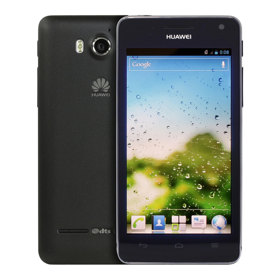
U8950 Maintenance Guide V1.0 1 Product Overview Product Overview 1.1 Appearance Figure 1-1 shows U8950. Figure 1-1 U8950 1.2 Features Table 1-1 lists the product features. 2012-10-22 Huawei Proprietary and Confidential... - Page 6 U8950 Maintenance Guide V1.0 1 Product Overview Table 1-1 U8950 product features Item Description Form factor Bar-type Display Size: 4.5 inches Type: TFT touchscreen Colors: 16 million colors Resolution: 960 x 540 pixels Dimensions 134 mm x 67.5 mm x 10.8 mm (5.28 in. x 2.66 in. x 0.43 in.)
- Page 7 U8950 Maintenance Guide V1.0 1 Product Overview Item Description Ports Standard micro-USB port, microSD card slot, and 3.5 mm headset jack Processor Qualcomm MSM8225, dual-core, 1.2 GHz Storage space ROM: 4 GB (Available space: 2 GB) RAM: 768 MB...
- Page 8 U8950 Maintenance Guide V1.0 1 Product Overview Item Description NOTE AF: autofocus BSI: backside illumination EDR: Enhanced Data Rate FF: fixed focus FM: frequency modulation GPRS: general packet radio service GSM: Global System for Mobile Communications HSDPA: High-Speed Downlink Packet Access...
-
Page 9: Applicable Scope And Precautions
2.1 Applicable Scope This document provides repair instructions for technicians at service centers authorized by Huawei. Being Huawei proprietary, this document is accessible only for authorized service centers and companies. Although every effort was made to ensure the accuracy of this document, errors may still exist. -
Page 10: Exploded View And Components
U8950 Maintenance Guide V1.0 3 Exploded View and Components Exploded View and Components 3.1 Exploded View The components listed in Figure 3-1 are structural parts of the phone, and cannot be used as reference when requesting spare parts. Figure 3-1 shows the U8650 exploded view. -
Page 11: Components List
U8950 Maintenance Guide V1.0 3 Exploded View and Components 3.2 Components List Table 3-1 lists the components of U8650. Table 3-1 Components of U8650 Description Quantity LCD protector Touchscreen Receiver ornament Front cover assembly Receiver M1.4 screw Receiver FPC Main PCBA... - Page 12 U8950 Maintenance Guide V1.0 3 Exploded View and Components Description Quantity NOTE CMII: FPC: flexible printed circuit LCD: liquid crystal display PCBA: Printed Circuit Board Assembly 2012-10-22 Huawei Proprietary and Confidential...
-
Page 13: Components On The Pcba
U8950 Maintenance Guide V1.0 4 Components on the PCBA Components on the PCBA Figure 4-1 and Figure 4-2 show the components on the top and bottom sides of the PCBA. Figure 4-1 Components on the PCBA top side J1601 TP BTB... - Page 14 Table 4-1 is provided for reference only. It is subject to changes without any notices. The latest component list is available on Huawei's ITEM information system. If you have any questions, contact your local technical support. Table 4-1 U8650 BOM list...
- Page 15 U8950 Maintenance Guide V1.0 4 Components on the PCBA BOM Code Description Location No. IC,WCDMA/GSM Dualmode BASEBAND PROCESSOR MSM8225-0-AA,1.2V/1.8V/2.85V,5 76 NSP(Pb free) Power Management 39200332 U201 IC(PM8029),3.0–4.4V,140WLNSP(p b-free),Terminal Dedicated 40060391 MCP,4GB(x8) U1700 eMMC,52MHz,1024KB,3.3V/1.8V, FBGA153,6Gb(x32) LPDDR1,Terminal Dedicated 47100551 RF Power Amplifying U3401 Module,880–915MHz,31dB max.
- Page 16 U8950 Maintenance Guide V1.0 4 Components on the PCBA BOM Code Description Location No. rminal Dedicated 39110620 Power Driver,1.5A LED flash driver U1002 IC,CSP,Terminal Dedicated 15060228 MOSFET,P Q201 Channel,-12V,-2.4A,112mohm,-8V, SOT23,from 15060150,TS16949,Terminal Dedica 22050053 Microphone, -44dB, D4.0mm*1.3m MIC1502 m,SMT,Terminal Dedicated 07050089 NTC,47000ohm,0402,1.0*0.5*0.35m...
-
Page 17: Software Upgrade
U8950 Maintenance Guide V1.0 5 Software Upgrade Software Upgrade 5.1 Upgrade Preparation Prepare the items listed in Table 5-1 Table 5-1 Items to be prepared before a software upgrade Category Item Description Upgrade Operating system: Windows 2000/Windows Computer environment USB cable... -
Page 18: Upgrade Using The Phone Driver
U8950 Maintenance Guide V1.0 5 Software Upgrade Figure 5-1 Hardware connection USB Cable U8950 5.3 Upgrade Using the Phone Driver 5.3.1 Installing the Phone Driver To install the phone driver on the computer, perform the following steps: Step 1 Double-click the Handset Windriver.exe file, and click Next in the displayed dialog box to start the installation. - Page 19 U8950 Maintenance Guide V1.0 5 Software Upgrade Step 3 Click Install. 2012-10-22 Huawei Proprietary and Confidential...
- Page 20 U8950 Maintenance Guide V1.0 5 Software Upgrade The installation progress is displayed, as shown in the following figure. Step 4 After the installation is complete, click Finish. 2012-10-22 Huawei Proprietary and Confidential...
-
Page 21: Performing A Normal Upgrade
U8950 Maintenance Guide V1.0 5 Software Upgrade After the phone driver is installed, you can view the port information Android Adapter PCUI (COM5) in the computer's Device Manager shown in the following figure. ----End 5.3.2 Performing a Normal Upgrade To conduct a normal upgrade, perform the following steps: Step 1 Power the phone on, and use the USB cable to connect the phone to the computer on which the phone driver and the upgrade tool have been installed. - Page 22 U8950 Maintenance Guide V1.0 5 Software Upgrade Step 3 Enter the password Huawei and click OK. In the displayed dialog box, select Allow upgrade for the Second time, Firmware, and Please Choose The Configuration File, and select the XML configuration file in the upgrade tool's root directory as required. Click Next.
-
Page 23: Performing A Forcible Upgrade
U8950 Maintenance Guide V1.0 5 Software Upgrade The upgrade automatically starts. After the upgrade, the phone automatically restarts. ----End 5.3.3 Performing a Forcible Upgrade If the mobile phone fails to start, use either of the following methods to perform a forcible... - Page 24 U8950 Maintenance Guide V1.0 5 Software Upgrade Table 5-2 Upgrade failures and solutions Failure Troubleshooting Check that there is no other driver conflicting with the USB driver for the upgrade. (PC) Failed to detect the phone. Check that the USB driver has been properly installed.
-
Page 25: Maintenance Tools
U8950 Maintenance Guide V1.0 6 Maintenance Tools Maintenance Tools Name: constant-temperature heat gun Usage: to heat components Name: constant-temperature heat gun Usage: to heat components Name: soldering iron Usage: to maintain and solder components Name: DC power supply Usage: to supply DC current... - Page 26 U8950 Maintenance Guide V1.0 6 Maintenance Tools Name: lead-free solder wire Usage: for soldering Name: digital multimeter Usage: to measure during repair Name: toolkit Usage: to assemble and disassemble components Name: electric screwdriver Usage: to fasten and remove screws 2012-10-22...
-
Page 27: Disassembly Procedure
U8950 Maintenance Guide V1.0 7 Disassembly Procedure Disassembly Procedure 7.1 Disassembling a Bare Phone For details, see the following figures. 1. Ensure that the ESD wrist strap is properly 2. Remove battery cover. connected to the ground. 3. Remove the screws from the rear cover. - Page 28 U8950 Maintenance Guide V1.0 7 Disassembly Procedure 5. Detach the RF cable. 6. Separate the FPC connector from the front cover. 7. Remove the screws from the PCBA and front 8. Take out the rear camera. cover. 9. Lift the BTB connector. The PCBA and front 10.
-
Page 29: Disassembling The Touchscreen
U8950 Maintenance Guide V1.0 7 Disassembly Procedure 11. Detach the RF cable from the PCBA. 12. Take out the PCBA. 7.2 Disassembling the Touchscreen For details, see the following figures. 1. Place the front cover assembly to the touchscreen 2. Push the four blocks to fix the front cover. - Page 30 U8950 Maintenance Guide V1.0 7 Disassembly Procedure Note that use the sucker for the touchscreen's lower suckers contact the touchscreen surface closely. part only. Note that use the sucker for the touchscreen's lower part only. 6. Rotate the knob reversely to raise the 5.
-
Page 31: Disassembling The Lcd
U8950 Maintenance Guide V1.0 7 Disassembly Procedure disassembled. 7.3 Disassembling the LCD 2. Use a cotton swab or silicon swab to eject the 1. Use the heat gun to heat the bottom of the front LCD gently from the hole at the bottom of the cover assembly and adhesive area of the LCD with front cover assembly. -
Page 32: Assembly Procedure
U8950 Maintenance Guide V1.0 8 Assembly Procedure Assembly Procedure The assembly procedure for the U8950 is similar to the C8950D. For details, see the following figures. 1. Ensure that the ESD wrist strap is properly connected to the ground. 2. Attach the LCD to the front cover. Pay attention to the BTB connector on the FPC. - Page 33 U8950 Maintenance Guide V1.0 8 Assembly Procedure 5. Install the power key and volume key FPC to 6. Install the receiver to the front cover. the front cover. 7. Install the tri-color indicator and receiver FPC 8. Secure the screws.
- Page 34 U8950 Maintenance Guide V1.0 8 Assembly Procedure 12. Fit the PCBA and front cover and fasten the BTB 11. Install the front camera to the PCBA. connector. 13. Install the rear camera to the PCBA. 14. Secure the screws on the PCBA and front cover.
- Page 35 U8950 Maintenance Guide V1.0 8 Assembly Procedure 17. Attach the RF cable to the antenna board. 18. Effect diagram after the preceding components are installed 19. Install the speaker to the rear cover. 20. Fit the front and rear covers and secure the screws.
-
Page 36: Maintenance Records During Verification
U8950 Maintenance Guide V1.0 9 Maintenance Records During Verification Maintenance Records During Verification 9.1 Maintenance Records on Each Stage Stage Station of Fault Faulty Item Symptom Solution Board upgrade The upgrade The data was lost. The board was formatted and failed at 4%. - Page 37 U8950 Maintenance Guide V1.0 9 Maintenance Records During Verification Stage Station of Fault Faulty Item Symptom Solution MMI05C The design software It indicated an issue of probability touchscreen was faulty (resulting requiring further analysis by the malfunction in occasional errors R&D department.
- Page 38 U8950 Maintenance Guide V1.0 9 Maintenance Records During Verification Stage Station of Fault Faulty Item Symptom Solution MMI01F The software was The test was performed again after abnormal poorly loaded. the software was eliminated. display MMI01E The LCD BTB The BTB connector was re-soldered.
- Page 39 U8950 Maintenance Guide V1.0 9 Maintenance Records During Verification Stage Station of Fault Faulty Item Symptom Solution BT use The CT test was The test passed when testing the CT 3in1-chip-erro missed. before the BT. B01 uploading The CPU was...
- Page 40 U8950 Maintenance Guide V1.0 9 Maintenance Records During Verification Stage Station of Fault Faulty Item Symptom Solution MMI06E The tester inserted After confirmation by the tester, the headset the headset when headset was inserted on the correct malfunction testing the secondary stage and the test then passed.
- Page 41 U8950 Maintenance Guide V1.0 9 Maintenance Records During Verification Stage Station of Fault Faulty Item Symptom Solution MMI02A SIM The SIM card was The SIM card voltage, clocks, reset card detection worn, resulting in signals, and signal lines were all...
- Page 42 U8950 Maintenance Guide V1.0 9 Maintenance Records During Verification Stage Station of Fault Faulty Item Symptom Solution Loading No Android The voltage The voltage VREG_S1 was also Adapter PCUI VPH_PWR was short-circuited. After the inductor interface after short-circuited due L201 was disconnected, the end...
- Page 43 U8950 Maintenance Guide V1.0 9 Maintenance Records During Verification Stage Station of Fault Faulty Item Symptom Solution PT: H00001 The phone could be The USB port was re-soldered. (no port) powered on using the battery but not through the USB port.
- Page 44 U8950 Maintenance Guide V1.0 9 Maintenance Records During Verification Stage Station of Fault Faulty Item Symptom Solution MMI06F The vibrator was The abnormal sound persisted when abnormal faulty. the vibrator was powered directly. sound The antenna board was replaced and the test then passed.
- Page 45 U8950 Maintenance Guide V1.0 9 Maintenance Records During Verification Stage Station of Fault Faulty Item Symptom Solution MMI06A The incoming The main FPC was replaced and the vibrator material of the main test then passed. malfunction FPC was faulty. MMI05C...
- Page 46 U8950 Maintenance Guide V1.0 9 Maintenance Records During Verification Stage Station of Fault Faulty Item Symptom Solution MMI04D The proximity light The proximity light cover was proximity cover was reversely re-installed. light installed. malfunction MMI04C The incoming The problem of LCD incoming...
- Page 47 U8950 Maintenance Guide V1.0 9 Maintenance Records During Verification Stage Station of Fault Faulty Item Symptom Solution MMI03A key The shrapnel of the The shrapnel of the volume up key malfunction volume up key was was adjusted. deformed and could not contact the volume key FPC.
- Page 48 U8950 Maintenance Guide V1.0 9 Maintenance Records During Verification Stage Station of Fault Faulty Item Symptom Solution MMI01F The color of the Keep the defective LCD and conduct lower half of the further analysis. LCD was slightly yellow in the whitescreen test.
- Page 49 U8950 Maintenance Guide V1.0 9 Maintenance Records During Verification Stage Station of Fault Faulty Item Symptom Solution CT22301F GSM malfunction U1002 and U2101 were found short-circuited. Replace the two components. U3501 was poorly CT 22601F Re-solder U3501. soldered. CT200011 BC failure Perform BC again.
- Page 50 U8950 Maintenance Guide V1.0 9 Maintenance Records During Verification Stage Station of Fault Faulty Item Symptom Solution Upload B03A REG_S4 output U1002 and U1402 were found nothing, all voltages connected. Report this problem to were not stable, R&D for further analysis.
-
Page 51: Principles And Failure Analysis
The U8950 supports storage on the microSD card. It also supports the FM radio and recording function. The U8950 uses a color TFT LCD with a resolution of 800 x 480 pixels. It provides a micro-USB charging port and UIM card slot and supports polyphonic ringtones, vibration, and FM functions. -
Page 52: Baseband Unit
Circuit Block Diagram Working Principle The U8950 uses an independent power management chip PM8029, with the startup principle controlled using Qualcomm codes. During the startup process, the PM8029 power management chip converts the main power supply voltage (VHP_PWR) to various voltages listed in the following table. - Page 53 U8950 Maintenance Guide V1.0 10 Principles and Failure Analysis Troubleshooting Process The startup failure has three types: no current, weak current, or excessive current. Most of startup failures are caused by power supply exceptions. Troubleshoot the faults as follows: ...
- Page 54 U8950 Maintenance Guide V1.0 10 Principles and Failure Analysis If the U8950 fails to start, locate the fault by checking the startup current when the U8950 is powered using DC. No current failure troubleshooting Power-on failure Connect the phone to the fake...
- Page 55 U8950 Maintenance Guide V1.0 10 Principles and Failure Analysis Power-on failure Connect the phone to the fake battery and maintenance power supply, press the power key, and test the phone current. Weak current Check whether the Check U201. PM output voltage is normal.
-
Page 56: Charging Management Circuits
U8950 Maintenance Guide V1.0 10 Principles and Failure Analysis Power-on failure Connect the phone to the fake battery and maintenance power supply, press the power key, and test the current on the phone. Excessive current Check whether pin Check U201 and 3 of J1501 is J1501. - Page 57 U8950 Maintenance Guide V1.0 10 Principles and Failure Analysis Working Principle The PM8029 chip integrates a charging solution, which supports three charging states: trickle charging, constant current charging, and constant voltage charging. The three charging methods adopt the same route: VEXT_DC > VCHG > VPH_PWR > Q201, and pin 3 >...
- Page 58 U8950 Maintenance Guide V1.0 10 Principles and Failure Analysis The dedicated power chip FAN5402UCX is used to charge the U8095 with a current of 1 A. I2C is used for communication and control with two interfaces GPIO13 (I2C_SCL_DCDC) and GPIO98 (I2C_SDA_DCDC) respectively. This charging management chip (BQ24152) sources the power from VCHAG in the USB interface and is controlled by I2C.
- Page 59 U8950 Maintenance Guide V1.0 10 Principles and Failure Analysis Figure 10-2 Block diagram of the charging circuit 2012-10-22 Huawei Proprietary and Confidential...
- Page 60 U8950 Maintenance Guide V1.0 10 Principles and Failure Analysis The BQ24152 chip can work in three modes: charging mode, boost mode, and high impedance mode. In charging mode, the BQ24152 chip starts the charging process normally. Boost mode is USB-OTG mode. In high impedance mode, the BQ24152 chip does not charge the mobile phone and switches to standby mode.
- Page 61 U8950 Maintenance Guide V1.0 10 Principles and Failure Analysis In actual circuits, the hardware raises the OTG to approximately 1.4 V and limits the maximum current in the beginning of charging to 500 mA. After the charging process is detected, this limitation is removed using software. FAN5402UCX is capable of detecting its own temperature.
- Page 62 U8950 Maintenance Guide V1.0 10 Principles and Failure Analysis Charging failure Does the charge Replace the function properly? charger. Check whether the USB Re-solder connector J103 is J103. poorly soldered? Check whether C231 Check F101 and LB101. bears voltages. Check whether...
-
Page 63: Clock Circuit
U8950 Maintenance Guide V1.0 10 Principles and Failure Analysis Circuit Diagram Symbols in this Section Signal Name Function Test Reference Value or Oscillogram VEXT_DC Charging current input from a charger Input of the external USB power VCHG 0–5 V supply and the charging chip... - Page 64 U8950 Maintenance Guide V1.0 10 Principles and Failure Analysis Working Principle In the above figure, the 19.2 MHz clock outputs to the PM8029 and RTR6285A. The TPK_LO_ADJ controls the clock output precision. The TPK_LO_ADJ has two filtering circuits: from R204 to C232 and from R3101 to C3101, which outputs to the main chip through the PM8029 as the system main clock.
-
Page 65: Flash Memory Circuit
U8950 Maintenance Guide V1.0 10 Principles and Failure Analysis Circuit Diagram Symbols in this Section Test Reference Value or Signal Name Function Oscillogram XTAL32K Output from the 32.768 kHz _OUT main clock XTAL32K_IN Input from the 32.768 kHz main clock VREG_TCXO 19.2 MHz oscillator power... - Page 66 U8950 Maintenance Guide V1.0 10 Principles and Failure Analysis 2012-10-22 Huawei Proprietary and Confidential...
- Page 67 U8950 Maintenance Guide V1.0 10 Principles and Failure Analysis Working Principle The MSM7227A is able to visit the LPDDR2 through two high-speed buses EBI1. The LPDDR2 is connected to the MSM8255-0 in PoP (Package-on-package) mode. Meanwhile, the MSM7227A can also visit the external storage eMMC through a low-speed bus (EBI2), as shown in the following Figure 10-4.
- Page 68 U8950 Maintenance Guide V1.0 10 Principles and Failure Analysis Figure 10-4 U8950 memory port analysis The EMMC adopts 8-bit data cable for data transmission, and the U8950 adopts 4 GB EMMC. Troubleshooting Process Failure symptom: The phone cannot be powered on, or the startup current is less than 100 Solution: Upgrade or reinstall the phone's firmware, and check whether the VREG_DCDC_2P85 voltage and peripheral components of the flash memory are normal.
-
Page 69: Rf Unit
U8950 Maintenance Guide V1.0 10 Principles and Failure Analysis Signal Name Function Test Reference Value or Oscillogram SDC3_DATA1 Data line SDC3_DATA0 Data line SDC3_DATA7 Data line SDC3_DATA6 Data line SDC3_DATA5 Data line SDC3_DATA4 Data line SDC3_CLK Clock SDC3_CMD Command VREG_DCDC_2P8 Flash power 2.9 V... -
Page 70: Power Amplifier
U8950 Maintenance Guide V1.0 10 Principles and Failure Analysis Working Principle The RF antenna switch model of the main antenna is 47140032. Table 10-1 lists the control logic of 47140032 RF antenna switch. 47140032 RF antenna switch control logic Frequency Band... -
Page 71: Troubleshooting Process
U8950 Maintenance Guide V1.0 10 Principles and Failure Analysis 10.2.2 Troubleshooting Process No-reception failure troubleshooting process for IMT/PCS/CELL is shown in the following. 2012-10-22 Huawei Proprietary and Confidential... - Page 72 U8950 Maintenance Guide V1.0 10 Principles and Failure Analysis IMT/PCS/CELL reception failure Do not connect the RF cable. Check whether J3201 pin1 Check J3201. and pin 2 are connected. Check whether U3202 RF Check U3202 switch control signals are and U401.
- Page 73 U8950 Maintenance Guide V1.0 10 Principles and Failure Analysis No-transmission failure troubleshooting process for IMT/PCS/CELL is shown in the following. Ensure that the SIM card and the antenna are well connected. Then, troubleshoot the fault according to the following procedure.
-
Page 74: Peripheral Circuits
U8950 Maintenance Guide V1.0 10 Principles and Failure Analysis 10.3 Peripheral Circuits 10.3.1 Display Circuit Block Diagram 2012-10-22 Huawei Proprietary and Confidential... - Page 75 The U8950 uses the TFT 4.5-inch LCD that supports 540 x 960 pixels. The U8950 LCD employs the MIPI interface. It requires only two pairs of low voltage differential signal (LVDS) cables and a pair of power cables, and supports 60 Hz refreshment rate.
- Page 76 U8950 Maintenance Guide V1.0 10 Principles and Failure Analysis No Display of LCD Is the problem solved after the software is loaded? Check whether Check L1710 and the backlights U1303. function. Check whether J1302 Repair is well soldered. J1302. Return the phone to the manufacturer for repair.
-
Page 77: Vibration
U8950 Maintenance Guide V1.0 10 Principles and Failure Analysis 10.3.2 Vibration Circuit Block Diagram Working Principle The PM8029's VIB_DRV_N pin functions as the drive pin for the vibrator, which locates on the main board. When the motor is not vibrating, VPH_PWR and VIB_DRV_N are both at high level. - Page 78 U8950 Maintenance Guide V1.0 10 Principles and Failure Analysis No vibration Is the problem solved after the software is loaded? Check whether the Re-solder and check vibrator is poorly the component. soldered. Check the Check whether the vibrator power power supply supply is normal and the negative unit.
-
Page 79: Receiver And Speaker
U8950 Maintenance Guide V1.0 10 Principles and Failure Analysis 10.3.3 Receiver and Speaker Circuit Block Diagram 2012-10-22 Huawei Proprietary and Confidential... - Page 80 U8950 Maintenance Guide V1.0 10 Principles and Failure Analysis Working Principle 2012-10-22 Huawei Proprietary and Confidential...
- Page 81 U8950 Maintenance Guide V1.0 10 Principles and Failure Analysis Figure 10-5 Internal structure of the audio processing unit The U8185 provides three types of audio output: Receiver output: Signals are output by the CPU. Speaker output: Signals are output by the PM8029 to the PA and to the speaker.
-
Page 82: Microphone
U8950 Maintenance Guide V1.0 10 Principles and Failure Analysis After a call is established, no sound can be heard by the other party. Is the problem solved after the software is loaded? Is the volume setting is Replace the volume key. - Page 83 10 Principles and Failure Analysis Working Principle The U8950 board provides the primary and secondary microphones for collecting different voice signals. The U8950 processes the collected voice signals to filter environmental noises. The U8950 adopts the following power supplies: ...
- Page 84 U8950 Maintenance Guide V1.0 10 Principles and Failure Analysis MSM_MICBIAS: Primary microphone 7227A MIC_BIAS Troubleshooting Process Failure: No sound is picked up or transmitted during a call. Solution: After a call is established, no sound can be heard by the...
-
Page 85: Headset
The headphone MIC is supplied with power by MIC_BIAS1 (PM8029/HSED_BIAS1), and it is used for headphone answer detection. U8950’s headphone is compatible with two line sequences. The iphone's headphone line sequence is compatible by default. The pull-up voltage is L10 3V. - Page 86 U8950 Maintenance Guide V1.0 10 Principles and Failure Analysis Troubleshooting Process Failure: No sound can be heard from the headphone. Solution: Replace the headset or the headset connector. No sound can be heard after the call setup. Is the volume setting is Set the volume.
-
Page 87: Sim Card
U8950 Maintenance Guide V1.0 10 Principles and Failure Analysis Signal Name Function Test Reference Value or Oscillogram HSED_HSKEY_AD Headset microphone Voltage change test HS_DETECT Headset insertion Voltage change detection Grounding signal of GND_MIC3 None the headset microphone 10.3.6 SIM Card... - Page 88 U8950 Maintenance Guide V1.0 10 Principles and Failure Analysis The U8950 SIM card interface is controlled by the input and output signals provided by the PM8029. Troubleshooting Process Failure: The USIM card cannot be detected. Solution: Verify that the UIM card slot is normal.
- Page 89 U8950 Maintenance Guide V1.0 10 Principles and Failure Analysis UIM card detection failure Check whether the problem is solved after U1701 is replaced. Re-solder or replace the Is the USIM card socket UIM card holder. normal. Check whether VREG_L16_UIM1 is normal Check VDD_SIM.
-
Page 90: I/O Connector
U8950 Maintenance Guide V1.0 10 Principles and Failure Analysis 10.3.7 I/O Connector Circuit Block Diagram Working Principle When connected to the I/O connector (USB connector), a charger provides the VCHG charging voltage to charge the battery. When the phone is connected to a computer using a USB cable, USB_HS_DN and USB_HS_DP are used for communication (for upgrading the phone's firmware, reading information from the phone and so on) between the phone and the computer. -
Page 91: Microsd Card Connector
U8950 Maintenance Guide V1.0 10 Principles and Failure Analysis 10.3.8 microSD Card Connector Circuit Block Diagram Working Principle The U1402 is added to provide the ESD protection and EMI filtering. Troubleshooting Process Failure: The microSD card cannot be detected or read. -
Page 92: Fm And Bluetooth
U8950 Maintenance Guide V1.0 10 Principles and Failure Analysis Micro-SD card detection failure Check whether the problem is solved after U1701 is replaced. Check whether U1402 Re-solder pins are connected. U1402. Upgrade the phone software and check whether the phone resumes its functions. - Page 93 U8950 Maintenance Guide V1.0 10 Principles and Failure Analysis Working Principle The U8950 uses Qualcomm BCM4330 to provide the Bluetooth, FM, and WLAN functions. Bluetooth adopts an independent antenna, and the FM adopts the left- and right-audio channels as the antenna.
- Page 94 U8950 Maintenance Guide V1.0 10 Principles and Failure Analysis MSM8225 Signal Line Definition GPIO_45 UART1_RX Reception signal GPIO_69 AUX_PCM_DIN PCM input GPIO_68 AUX_PCM_DOUT PCM output GPIO_70 AUX_PCM_SYNC PCM synchronization GPIO_71 AUX_PCM_CLK PCM clock GPIO_107 MSM_WAKES_BT: Waking up the host GPIO_27...
- Page 95 U8950 Maintenance Guide V1.0 10 Principles and Failure Analysis FM radio function failure Does the phone resume its FM radio function after having the headset replaced. Does the phone resume its FM radio function after having the headset jack re- soldered.
-
Page 96: Solder Points On The Pcb And Bga Chips
11 Solder Points on the PCB and BGA U8950 Maintenance Guide V1.0 Chips Solder Points on the PCB and BGA Chips Figure 11-1and Figure 11-2 show the solder points on the PCB and BGA chips. Figure 11-1 Top surface 2012-10-22... - Page 97 11 Solder Points on the PCB and BGA U8950 Maintenance Guide V1.0 Chips Figure 11-2 Bottom surface NOTE The blank, grounding, and solder points must be clearly marked. Colors used for the solder points figures must be distinguished, and the color indication must be explained.
- Page 98 11 Solder Points on the PCB and BGA U8950 Maintenance Guide V1.0 Chips Figure 11-3 Top-side silkscreen diagram Figure 11-4 Bottom side silkscreen diagram 2012-10-22 Huawei Proprietary and Confidential...
- Page 99 11 Solder Points on the PCB and BGA U8950 Maintenance Guide V1.0 Chips Attachment: 2012-10-22 Huawei Proprietary and Confidential...
-
Page 100: Functional Tests
U8950 Maintenance Guide V1.0 12 Functional Tests Functional Tests 12.1 Keys 开机键 音量+ 音量- 取消键 主页键 Menu button 12.2 MMI Test After the phone is correctly powered on, enter *#*#2846579#*#* using the keypad and then press the send key to enter the MMI test. Then select MMITEST and press the volume down key to start the MMI test. -
Page 101: Voice Call Test
U8950 Maintenance Guide V1.0 12 Functional Tests Board test: The phone directly proceeds to the next test if the board test is successful. microSD card test: The message "No microSD card" is displayed if the microSD card is not inserted. You can press the volume down key to proceed to the next test.