Mitsubishi Electric MELSERVO-J3 Series Instruction Manual
Sscnet interface direct drive servo
Hide thumbs
Also See for MELSERVO-J3 Series:
- Instruction manual (802 pages) ,
- Manual (668 pages) ,
- Handbook (590 pages)

Related Manuals for Mitsubishi Electric MELSERVO-J3 Series


Summary of Contents for Mitsubishi Electric MELSERVO-J3 Series
- Page 1 General-Purpose AC Servo Series SSCNET Interface Direct Drive Servo MODEL (Servo Amplifier) MR-J3- B-RJ080W MODEL (Direct Drive Motor) TM-RFM INSTRUCTION MANUAL...
- Page 2 Safety Instructions Please read the instructions carefully before using the equipment. To use the equipment correctly, do not attempt to install, operate, maintain, or inspect the equipment until you have read through this Instruction Manual, MR-J3- B Servo amplifier Instruction Manual, and appended documents carefully.
- Page 3 1. To prevent electric shock, note the following WARNING Before wiring or inspection, turn off the power and wait for 15 minutes or more until the charge lamp turns off. Then, confirm that the voltage between P( ) and N( ) is safe with a voltage tester and others. Otherwise, an electric shock may occur.
- Page 4 3. To prevent injury, note the following CAUTION Only the voltage specified in the Instruction Manual should be applied to each terminal, Otherwise, a burst, damage, etc. may occur. Connect the terminals correctly to prevent a burst, damage, etc. Ensure that polarity ( , ) is correct.
- Page 5 CAUTION Do not subject the rotor of the direct drive motor to more than the permissible load. Otherwise, the rotor may break. When the equipment has been stored for an extended period of time, contact your local sales office. When you keep or use it, please fulfill the following environment. Environment Item Servo amplifier...
- Page 6 CAUTION Connect the servo amplifier power supply output (U, V, and W) to the direct drive motor power supply input (U, V, and W) directly. Do not let a magnetic contactor, etc. intervene. Otherwise, it may cause a malfunction. Servo amplifier Direct drive motor Servo amplifier Direct drive motor...
- Page 7 (5) Corrective actions CAUTION When it is assumed that a hazardous condition may take place at the occur due to a power failure or a product fault, use a direct drive motor with an external brake mechanism for the purpose of prevention. When any alarm has occurred, eliminate its cause, ensure safety, and deactivate the alarm before restarting operation.
- Page 8 DISPOSAL OF WASTE Please dispose a servo amplifier, battery (primary battery) and other options according to your local laws and regulations. EEP-ROM life The number of write times to the EEP-ROM, which stores parameter settings, etc., is limited to 100,000. If the total number of the following operations exceeds 100,000, the servo amplifier may fail when the EEP-ROM reaches the end of its useful life.
- Page 9 Relevant manuals Manual name Manual No. MELSERVO-J3 Series Instructions and Cautions for Safe Use of AC Servos IB(NA)0300077 MELSERVO-J3 Series MR-J3- B Servo Amplifier Instruction Manual SH(NA)030051 This Instruction Manual describes the functions unique to the SSCNET Interface Direct Drive Servo.
-
Page 10: Table Of Contents
CONTENTS 1. FUNCTIONS AND CONFIGURATION 1 - 1 to 1 -12 1.1 Summary ..............................1 - 1 1.2 Servo amplifier standard specifications....................1 - 3 1.3 Function list .............................. 1 - 4 1.4 Model code definition ..........................1 - 5 1.5 Combinations of servo amplifiers and direct drive motor................ - Page 11 4. OPERATION AND FUNCTIONS 4 - 1 to 4 -18 4.1 Startup ..............................4 - 1 4.2 Magnetic pole detection ........................... 4 - 2 4.2.1 Preparation for the magnetic pole detection ..................4 - 2 4.2.2 Driving when magnetic pole is detected................... 4 - 3 4.2.3 Magnetic pole detection method setting...................
- Page 12 9.1.1 Combinations of cable and connector set ..................9 - 2 9.1.2 Encoder connector set ........................9 - 4 9.2 Absolute position storage unit MR-BTAS01................... 9 -10 APPENDIX App.- 1 to App.- 8 App. 1 Parameter list..........................App.- 1 App. 2 Signal layout recording paper ......................App.- 3 App.
- Page 13 MEMO...
-
Page 14: Functions And Configuration
1. FUNCTIONS AND CONFIGURATION 1. FUNCTIONS AND CONFIGURATION 1.1 Summary To meet high-accuracy and high-efficiency requirements in areas including semiconductor and liquid crystal related machines, and surface mount device placement machines, a system with a direct drive motor in a drive axis has been increased. - Page 15 1. FUNCTIONS AND CONFIGURATION Differences Classification Item Remarks Direct drive servo MR-J3- B (MR-J3- B-RJ080W) External I/O signal Stroke limit input signal Required (when Not required Automatically turns on in the (FLS, RLS) magnetic pole is parameter setting. detected) Motor pole adjustment Magnetic pole detection Required Not required (adjusted Automatically executed at the...
-
Page 16: Servo Amplifier Standard Specifications
1. FUNCTIONS AND CONFIGURATION 1.2 Servo amplifier standard specifications Servo amplifier 100B 350B 500B MR-J3- -RJ080W Item Rated voltage 3-phase 170VAC Rated current 17.0 28.0 Voltage/frequency 3-phase or 1-phase 200 to 230VAC, 50/60Hz 3-phase 200 to 230VAC, 50/60Hz Rated current 16.0 21.7 Permissible voltage fluctuation... -
Page 17: Function List
1. FUNCTIONS AND CONFIGURATION 1.3 Function list The following table lists the functions of this servo. For details of the functions, refer to the reference field. Function Description Reference Absolute position detection Merely setting a home position once makes home position return unnecessary Chapter 9 system at every power-on. -
Page 18: Model Code Definition
Applicable power supply 2.2A 1PH200-230V 50Hz/60Hz Rated output current OUTPUT 170V 0-360Hz 1.5A SERIAL A18001050 Serial number KCC-REI-MEK-TC300A***G51 MITSUBISHI ELECTRIC CORPORATION KC mark number MADE IN JAPAN Country of origin (2) Model Direct drive motor compatible Series name SSCNET Interface... -
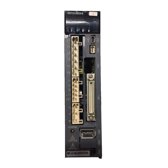
Page 19: Parts Identification
1. FUNCTIONS AND CONFIGURATION 1.6 Parts identification (1) MR-J3-100B-RJ080W or less Detailed Name/Application explanation Display The 3-digit, seven-segment LED shows the servo status and alarm number. Rotary axis setting switch (SW1) ON 4E Used to set the axis No. of servo amplifier. TEST Refer to the MR-J3- B... - Page 20 1. FUNCTIONS AND CONFIGURATION (2) MR-J3-350B-RJ080W Detailed Name/Application explanation Display The 3-digit, seven-segment LED shows the servo status and alarm number. Rotary axis setting switch (SW1) Used to set the axis No. of servo amplifier. Refer to the MR-J3- B Servo ON 4E Amplifier...
- Page 21 1. FUNCTIONS AND CONFIGURATION (3) MR-J3-500B-RJ080W POINT The servo amplifier is shown without the front cover. For removal of the front cover, refer to section 1.7.2 of the MR-J3- B Servo Amplifier Instruction Manual. Detailed Name/Application explanation Display The 3-digit, seven-segment LED shows the servo status and alarm number.
-
Page 22: Configuration Including Auxiliary Equipment
1. FUNCTIONS AND CONFIGURATION 1.7 Configuration including auxiliary equipment POINT Equipment other than the servo amplifier and direct drive motor are optional or recommended products. (1) MR-J3-100B-RJ080W or less Personal (Note 3) R S T computer Power supply MR Configurator Molded-case circuit breaker Servo amplifier... - Page 23 1. FUNCTIONS AND CONFIGURATION (2) MR-J3-350B-RJ080W (Note 3) R S T Power supply Molded-case circuit breaker (MCCB) or fuse Magnetic contactor (MC) Personal computer MR Configurator (Note 2) Line noise filter Servo amplifier (FR-BLF) Junction terminal block Servo system CN1A controller or Front axis (Note 2) servo amplifier CN1B...
- Page 24 1. FUNCTIONS AND CONFIGURATION (3) MR-J3-500B-RJ080W (Note 3) R S T Power supply Personal computer MR Configurator Molded-case circuit breaker (MCCB) or fuse Servo amplifier Magnetic contactor Junction (MC) terminal block (Note 2) Servo system (Note 1) CN1A controller or Front axis Line noise Battery servo amplifier CN1B...
- Page 25 1. FUNCTIONS AND CONFIGURATION MEMO 1 - 12...
-
Page 26: Direct Drive Motor
2. DIRECT DRIVE MOTOR 2. DIRECT DRIVE MOTOR 2.1 Rating plate AC DIRECT DRIVE MOTOR Model TM-RFM002C20 Input power supply INPUT 3AC 45.7V 1.2A Rated output TORQUE 2Nm 200r/min IP42CI.F 5.2kg Rated speed, IP rating, Insulation class, Mass SER.No. 000000 12Y Serial number (Note) Country of origin Note. -
Page 27: Installation
2. DIRECT DRIVE MOTOR 2.3 Installation WARNING To prevent electric shock, ground each equipment securely. Stacking in excess of the limited number of product packages is not allowed. Install the equipment on incombustible material. Installing it directly or close to combustibles will lead to a fire. -
Page 28: Equipment Configuration
2. DIRECT DRIVE MOTOR 2.3.1 Equipment configuration This section explains the system configuration with a direct drive motor. Note the following points when using a direct drive motor. (1) Minimum oscillation angle If the direct drive motor rotates repeatedly by a small angle (by 70° or less), make the direct drive motor rotate by 90°... -
Page 29: Installation Orientation
2. DIRECT DRIVE MOTOR 2.3.2 Installation orientation The following table indicates the installation orientation of the direct drive motor. Direct drive motor series Direction of installation TM-RFM May be installed in any direction. 2.3.3 Load remove precautions POINT During assembling, the rotor end must not be hammered. Doing so can cause the encoder to fail. -
Page 30: Protection From Oil And Water
2. DIRECT DRIVE MOTOR 2.3.5 Protection from oil and water Provide adequate protection to prevent foreign matter, such as oil and water from entering the direct drive motor rotor. When installing the direct drive motor, consider the items in this section. (1) Do not use the direct drive motor with its cable soaked in oil or water. -
Page 31: Inspection
2. DIRECT DRIVE MOTOR 2.3.6 Inspection Before starting maintenance and/or inspection, turn off the power and wait for 15 minutes or more until the charge lamp turns off. Then, confirm that the voltage between P( ) and N( ) is safe with a voltage tester and others. Otherwise, an WARNING electric shock may occur. -
Page 32: Machine Accuracies
2. DIRECT DRIVE MOTOR 2.3.8 Machine accuracies The following table indicates the machine accuracies of the direct drive motor around the rotor (output shaft) and mounting. (except the optional products) Item Measured part Accuracy [mm] Runout of flange surface about rotor (output shaft) 0.05 Runout of fitting outer diameter of flange surface 0.07... -
Page 33: Connectors Used For Direct Drive Motor Wiring
2. DIRECT DRIVE MOTOR 2.4 Connectors used for direct drive motor wiring POINT The IP rating indicated is the connector's protection against ingress of dust and water when the connector is connected to a servo amplifier, direct drive motor and absolute position storage unit. -
Page 34: Wiring Connectors (Connector Configurations A B C D E F)
2. DIRECT DRIVE MOTOR 2.4.2 Wiring connectors (Connector configurations A B C D E F) Cord Plug clamp Plug (Hirose Electric) Recommended cable (Bando Densen) Direct drive motor encoder connector or absolute Overall Connector position storage unit diameter of Feature connector configuration cable... - Page 35 2. DIRECT DRIVE MOTOR Plug Cable clamp Plug (DDK) Cable clamp (DDK) Overall Connector Direct drive motor power diameter of Feature configuration supply connector (Note 2) Type Model name cable Model name [mm] (Reference) IP67 CE05-6A22-22SD-D-BSS 9.5 to 13 CE3057-12A-2-D EN compliant Applicable wire size: AWG 10 to 8 12.5 to 16...
-
Page 36: Connector Outline Drawings
2. DIRECT DRIVE MOTOR 2.4.3 Connector outline drawings The connector outline drawings for wiring the direct drive motor are shown below. (1) Hirose Electric (a) RM15WTPZK-12S RM15WTPZ-12P(72) Model Connector configuration (Note) RM15WTPZK-12S RM15WTPZ-12P(72) Note. For the connector configuration, refer to section 2.4.2. [Unit: mm] Spanner hook gap dimension: 18 M19 1... - Page 37 2. DIRECT DRIVE MOTOR (b) CE05-6A18-10SD-D-BSS CE05-6A22-22SD-D-BSS CE05-6A32-17SD-D-BSS [Unit: mm] Positioning key Connector configuration Model C 0.8 D or less 0.38 (Note) CE05-6A18-10SD-D-BSS 1 1/8-18UNEF-2B 34.13 32.1 1-20UNEF-2A CE05-6A22-22SD-D-BSS 1 3/8-18UNEF-2B 40.48 38.3 1 3/16-18UNEF-2A CE05-6A32-17SD-D-BSS 2-18UNS-2B 56.33 54.2 1 3/4-18UNS-2A Note.
- Page 38 2. DIRECT DRIVE MOTOR (d) D/MS3106B14S-2S D/MS3106B18-10S D/MS3106B22-22S D/MS3106B32-17S [Unit: mm] L or less J 0.12 Connector Model name configuration (Note) D/MS3106B14S-2S 7/8-20UNEF 13.49 42.88 28.57 3/4-20UNEF 8.00 D/MS3106B18-10S 1 1/8-18UNEF 18.26 52.37 34.13 1-20UNEF 9.53 D/MS3106B22-22S 1 3/8-18UNEF 18.26 56.57 40.48 1 3/16-18UNEF 9.53 D/MS3106B32-17S 2-18UNS...
- Page 39 2. DIRECT DRIVE MOTOR (3) Daiwa Dengyo [Unit: mm] O-ring Width Width Width Width Length before Connector across across across across Applicable tightening Model name configuration flats corners flats corners cable OD (Note) YSO14-5 to 8 4 to 8.3 3/4-20UNEF-2B YSO14-9 to 11 7 to 11.3 Note.
-
Page 40: Tm-Rfm Series Direct Drive Motor
2. DIRECT DRIVE MOTOR 2.5 TM-RFM series direct drive motor This section provides information on the specifications and characteristics of the direct drive motor. When using the TM-RFM series direct drive motor, always read the Safety Instructions in the beginning of this manual in addition to this section. -
Page 41: Specification List
2. DIRECT DRIVE MOTOR 2.5.2 Specification list Direct drive motor TM-RFM series Item 002C20 004C20 006C20 006E20 012E20 018E20 Motor outer diameter (Frame dimensions) [mm] Compatible servo amplifier model MR-J3- -RJ080W 100B Rated output Continuous running [N m] duty (Note 1) Rated torque [oz in] 1700... - Page 42 2. DIRECT DRIVE MOTOR Direct drive motor TM-RFM series Item 012G20 048G20 072G20 040J10 120J10 240J10 Motor outer diameter (Frame dimensions) [mm] Compatible servo amplifier model MR-J3- -RJ080W 350B 350B 350B 500B Rated output 1005 1508 1257 2513 Continuous running [N m] duty (Note 1) Rated torque...
- Page 43 2. DIRECT DRIVE MOTOR Note 1. When the power supply voltage drops, the output and the rated speed cannot be guaranteed. 2. If the load inertia moment ratio exceeds the indicated value, please contact your local sales office. 3. Note that the power supply equipment capacity will vary according to the power supply impedance. This value assumes that the power factor improving AC reactor or the power factor improving DC reactor is not used.
-
Page 44: Torque Characteristic
2. DIRECT DRIVE MOTOR 2.5.3 Torque characteristic POINT When using a machine which generates unbalanced torque including a vertical axis, use an absolute position detection system (Rrefer to section 2.3.1 (4)). It is recommended that the unbalanced torque is 70% or less of the rated torque. When the power supply input of the servo amplifier are 3-phase 200VAC or 1-phase 230VAC, the torque characteristic is indicated by the heavy line. -
Page 45: Outline Dimension Drawings
2. DIRECT DRIVE MOTOR 2.5.4 Outline dimension drawings The actual dimensions may be 1mm to 3mm larger. Design the machine side with some allowances. Apply general tolerances for the dimensions without tolerances. Inertia moment Output Mass Model J [ 10 kg m [kg] ([lb]) [oz in... - Page 46 2. DIRECT DRIVE MOTOR Inertia moment Output Mass Model J [ 10 kg m [kg] ([lb]) [oz in TM-RFM004C20 16.6 (90.8) 6.8 (15) [Unit: mm] 4- 9 mounting hole Use hexagon socket 6-M5 screw depth 8 head cap screw Z-phase mark Bottom Caution plate Encoder connector...
- Page 47 2. DIRECT DRIVE MOTOR Inertia moment Output Mass Model J [ 10 kg m [kg] ([lb]) [oz in TM-RFM006C20 22.4 (122) 8.4 (19) [Unit: mm] 4- 9 mounting hole Use hexagon socket 6-M5 screw depth 8 head cap screw Z-phase mark Caution plate Motor plate Encoder connector...
- Page 48 2. DIRECT DRIVE MOTOR Inertia moment Output Mass Model J [ 10 kg m [kg] ([lb]) [oz in TM-RFM006E20 74.0 (405) 11 (25) [Unit: mm] 4- 14 mounting hole Use hexagon socket 6-M5 screw depth 8 head cap screw Z-phase mark Caution plate Motor plate Encoder connector...
- Page 49 2. DIRECT DRIVE MOTOR Inertia moment Output Mass Model J [ 10 kg m [kg] ([lb]) [oz in TM-RFM012E20 111 (607) 15 (33) [Unit: mm] 4- 14 mounting hole Use hexagon socket head cap screw 6-M5 screw depth 8 Z-phase mark Caution plate Motor plate Encoder connector...
- Page 50 2. DIRECT DRIVE MOTOR Inertia moment Output Mass Model J [ 10 kg m [kg] ([lb]) [oz in TM-RFM018E20 149 (815) 18 (40) [Unit: mm] 4- 14 mounting hole Use hexagon socket head cap screw 6-M5 screw depth 8 Z-phase mark Caution plate Motor plate Encoder connector...
- Page 51 2. DIRECT DRIVE MOTOR Inertia moment Output Mass Model J [ 10 kg m [kg] ([lb]) [oz in TM-RFM012G20 238 (1300) 17 (38) [Unit: mm] 4- 14 mounting hole 6-M6 screw depth 10 Use hexagon socket head cap screw 2 2-M10 screw depth 19.5 Bottom Z-phase mark Caution plate...
- Page 52 2. DIRECT DRIVE MOTOR Inertia moment Output Mass Model J [ 10 kg m [kg] ([lb]) [oz in TM-RFM048G20 1005 615 (3360) 36 (80) [Unit: mm] 4- 14 mounting hole 6-M6 screw depth 10 Use hexagon socket 2 2-M10 screw depth 19.5 head cap screw Bottom Z-phase mark...
- Page 53 2. DIRECT DRIVE MOTOR Inertia moment Output Mass Model J [ 10 kg m [kg] ([lb]) [oz in TM-RFM072G20 1508 875 (4780) 52 (115) [Unit: mm] 6-M6 screw depth 10 4- 14 mounting hole Use hexagon socket 2 2-M10 screw depth 19.5 head cap screw Z-phase mark Caution plate...
- Page 54 2. DIRECT DRIVE MOTOR Inertia moment Output Mass Model J [ 10 kg m [kg] ([lb]) [oz in TM-RFM040J10 1694 (9260) 53 (120) [Unit: mm] 4- 18 mounting hole 2 2-M12 screw depth 25.5 6-M8 screw depth 13 Use hexagon socket head cap screw Z-phase mark Bottom...
- Page 55 2. DIRECT DRIVE MOTOR Inertia moment Output Mass Model J [ 10 kg m [kg] ([lb]) [oz in TM-RFM120J10 2513 3519 (19200) 91 (205) [Unit: mm] 2 2-M12 screw depth 25.5 4- 18 mounting hole Use hexagon socket 6-M8 screw depth 13 head cap screw Z-phase mark Bottom...
- Page 56 2. DIRECT DRIVE MOTOR Inertia moment Output Mass Model J [ 10 kg m [kg] ([lb]) [oz in TM-RFM240J10 5027 6303 (34500) 146 (325) [Unit: mm] 4- 18 mounting hole 2 2-M12 screw depth 25.5 6-M8 screw depth 13 Use hexagon socket head cap screw Bottom Z-phase mark...
-
Page 57: Connection Of Servo Amplifier And Direct Drive Motor
2. DIRECT DRIVE MOTOR 2.5.5 Connection of servo amplifier and direct drive motor Any person who is involved in wiring should be fully competent to do the work. Ground the direct drive motor securely. Do not attempt to wire the direct drive motor until it has been installed. Otherwise, it may cause an electric shock. - Page 58 2. DIRECT DRIVE MOTOR (1) Connection instructions To avoid a malfunction, connect the power supply phases (U, V, and W) of the servo amplifier and the direct drive motor correctly. CAUTION Do not connect AC power supply directly to the direct drive motor. Otherwise, it may cause a malfunction.
- Page 59 2. DIRECT DRIVE MOTOR MEMO 2 - 34...
-
Page 60: Signals And Wiring
3. SIGNALS AND WIRING 3. SIGNALS AND WIRING Any person who is involved in wiring should be fully competent to do the work. Before wiring, turn off the power and wait for 15 minutes or more until the charge lamp turns off. Then, confirm that the voltage between P( ) and N( ) is safe with a voltage tester and others. -
Page 61: Precautions For This Chapter
3. SIGNALS AND WIRING 3.1 Precautions for this chapter The following items are not described in this chapter. Since these descriptions are the same as those of MR- J3- B Servo Amplifier, refer to the MR-J3- B Servo Amplifier Instruction Manual. Item MR-J3- B Servo Amplifier Instruction Manual Explanation of power supply system... -
Page 62: Selection Example Of Wires
3. SIGNALS AND WIRING 3.2.1 Selection example of wires POINT Selection condition of wire size is as follows. Construction condition: One wire is constructed in the air Wire length: 30m or less (1) When using the 600V Grade heat-resistant polyvinyl chloride insulated wire (HIV wire) Selection example of wire size when using HIV wires is indicated below. -
Page 63: Connection Example
3. SIGNALS AND WIRING 3.2.2 Connection example (1) For 3-phase 200 to 230VAC power supply to MR-J3-20B-RJ080W to MR-J3-100B-RJ080W MR-J3-350B-RJ080W (Note 3) (Note 6) Malfunct Forced stop Controller forced stop Direct drive motor Servo amplifier MC (Note 8) CNP1 MCCB 3-phase CNP3 (Note 5) - Page 64 3. SIGNALS AND WIRING (2) For 1-phase 200 to 230VAC power supply to MR-J3-20B-RJ080W to MR-J3-70B-RJ080W (Note 6) (Note 3) Forced stop Malfunction Controller forced stop Direct drive motor Servo amplifier MC (Note 8) CNP1 MCCB 1-phase CNP3 (Note 5) 200 to 230VAC Motor...
- Page 65 3. SIGNALS AND WIRING (3) MR-J3-500B-RJ080W (Note 3) (Note 6) Malfunction Forced stop Controller forced stop Direct drive motor Servo amplifier MC (Note 8) MCCB 3-phase (Note 5) Built-in 200 to Motor regenerative 230VAC resistor (Note 2) (Note 7) Encoder Encoder cable (Note 1) 24VDC...
-
Page 66: I/O Signal Connection Example
3. SIGNALS AND WIRING 3.3 I/O signal connection example POINT For details of each signal, refer to chapter 3 of the MR-J3- B Servo Amplifier Instruction Manual. Servo amplifier 10m or less 10m or less (Note 10) (Note 12) (Note 12) (Note 2) 24VDC DICOM... - Page 67 3. SIGNALS AND WIRING Note 1 To prevent an electric shock, always connect the protective earth (PE) terminal ( ) of the servo amplifier to the protective earth (PE) of the cabinet. 2. Connect the diode in the correct direction. If it is connected reversely, the servo amplifier will be faulty and will not output signals, disabling the forced stop (EM1) and other protective circuits.
-
Page 68: Connector And Signal Arrangements
3. SIGNALS AND WIRING 3.4 Connector and signal arrangements POINT The pin configurations of the connectors are as viewed from the cable connector wiring section. The servo amplifier front view shown is for MR-J3-20B-RJ080W or less. For the appearances and connector layouts of other servo amplifiers, refer to chapter 7 SERVO AMPLIFIER OUTLINE DRAWINGS. -
Page 69: Internal Connection Diagram
3. SIGNALS AND WIRING 3.5 Internal connection diagram 3.5.1 Incremental system Servo amplifier Approx. Forced stop 5.6k DICOM (Note 2) (Note 1) Approx. (Note 2) 5.6k 24VDC DICOM DOCOM Differential line driver output <Isolated> (35mA or less) Analog monitor 10VDC VBUS 10VDC Direct drive... - Page 70 3. SIGNALS AND WIRING 3.5.2 Absolute position detection system Servo amplifier Approx. Forced stop 5.6k DICOM (Note 2) (Note 1) Approx. (Note 2) 5.6k 24VDC DICOM DOCOM Differential line driver output <Isolated> (35mA or less) Analog monitor 10VDC VBUS 10VDC Absolute position Direct drive strage unit (Note 4)
- Page 71 3. SIGNALS AND WIRING MEMO 3 - 12...
-
Page 72: Absolute Position Detection System
4. OPERATION AND FUNCTIONS 4. OPERATION AND FUNCTIONS 4.1 Startup Start up the direct drive servo referring to the following procedure. Perform this procedure once at startup Execution of installation and wiring Absolute position detection system Incremental system Absolute position detection system? Can you manually turn on the Z-phase pulse of the direct... -
Page 73: Magnetic Pole Detection
4. OPERATION AND FUNCTIONS 4.2 Magnetic pole detection POINT Magnetic pole detection is not required for the configured absolute position detection system where the Z-phase pulse can be turned on manually. For this operation, always connect the direct drive motor encoder and the servo amplifier and turn on the control circuit power supply of the servo amplifier. -
Page 74: Driving When Magnetic Pole Is Detected
4. OPERATION AND FUNCTIONS 4.2.2 Driving when magnetic pole is detected Note that the magnetic pole detection is automatically started simultaneously with WARNING turning on the servo-on command. If the magnetic pole detection is not executed properly, the direct drive motor may CAUTION run unexpectedly. - Page 75 4. OPERATION AND FUNCTIONS (1) For the incremental system For the incremental system, the magnetic pole detection is required every time the power is turned on. By turning on the servo-on command from the controller after the power-on, the magnetic pole detection is automatically carried out.
- Page 76 4. OPERATION AND FUNCTIONS (2) For the absolute position detection system POINT Be sure to turn on the Z-phase pulse in JOG operation after the magnetic pole detection. Carry out the magnetic pole detection referring the following procedure. (a) Set the parameter No.PS01 (Special function selection 1) to " 1 (Magnetic pole detection always valid)".
-
Page 77: Magnetic Pole Detection Method Setting
4. OPERATION AND FUNCTIONS 4.2.3 Magnetic pole detection method setting Set a magnetic pole detection method to the 1st digit (method selection for the magnetic pole detection) of parameter No.PS08. Parameter No.PS08 Method selection for the magnetic pole detection 0: Position detection method 4: Minute position detection method 4.2.4 Setting the magnetic pole detection voltage level of the position detection method Set the voltage level in parameter No.PS09 (Magnetic pole detection voltage level) to perform magnetic pole... - Page 78 4. OPERATION AND FUNCTIONS (3) Setting example Magnetic pole detection Parameter No.PS09 setting value Overload and overcurrent alarm Existence or nonexistence Carry out the magnetic pole detection repeatedly while making An alarm has occurred when the setting value the setting value of the parameter No.PS09 larger. of the parameter No.PS09 is set to 70.
-
Page 79: Magnetic Pole Detection Method Using Mr Configurator
4. OPERATION AND FUNCTIONS 4.2.5 Magnetic pole detection method using MR Configurator The following shows the procedure of the magnetic pole detection using MR Configurator. (1) Magnetic pole detection using position detection method Magnetic pole detection After confirming that the stroke limits (FLS and RLS) and the forced stop (EM1) are on, turn the power of servo amplifier off once and then turn it on again. - Page 80 4. OPERATION AND FUNCTIONS (2) Magnetic pole detection using minute position detection method Magnetic pole detection 1) After confirming that the stroke limits (FLS and RLS) and the forced stop (EM1) are on, turn the power of servo amplifier off once and then turn it on again. After switching the test operation select switch (SW2-1) of the servo amplifier to "Up", turn the power of servo amplifier off once and then turn it on again.
-
Page 81: Operation From The Controller
4. OPERATION AND FUNCTIONS (3) Transition of the servo amplifier display (3-digit 7-segment LED) when detecting magnetic poles The servo amplifier display (3-digit 7-segment LED) shifts as shown below when the magnetic poles are detected properly using MR Configurator. Magnetic pole detection Detecting completed... -
Page 82: Servo System Controller Setting
4. OPERATION AND FUNCTIONS 4.3.2 Servo system controller setting (1) Setting instructions When using the direct drive servo, set it as described in this section. For other servo parameters and positioning control parameters, set them in the same method as that of MR-J3- B servo amplifier. The following servo parameters will be valid by turning the power of servo amplifier off once and then turning it on again after writing to the servo amplifier from the controller. - Page 83 4. OPERATION AND FUNCTIONS (2) Sequence program example of servo parameters on the positioning module POINT For QD74MH /QD75MH , the parameter error (37) will occur if servo parameters are not initialized. The number of write time to the flash ROM is limited to 100,000. For this reason, try to write to the flash ROM only when changing the servo parameter instead of writing with every sequence program.
- Page 84 4. OPERATION AND FUNCTIONS (a) Sequence program example when QD74MH is used The following shows the example of writing the axis No.1 servo parameter to the flash ROM. After changing the servo parameter, turn on the power of QD74MH again or reset the CPU, then send the setting value to the servo amplifier.
- Page 85 4. OPERATION AND FUNCTIONS (b) Sequence program example when QD75MH is used The following shows the example of writing the axis No.1 servo parameter to the flash ROM. After changing the servo parameter, turn on the power of QD75MH again or reset the CPU, then send the setting value to the servo amplifier.
- Page 86 4. OPERATION AND FUNCTIONS (3) QD75MH buffer memory address of special setting parameter (No.PS Description Buffer memory address Initial Unit Symbol value Name Axis 1 Axis 2 Axis 3 Axis 4 (Note) PS01 **LIT1 Special function selection 1 0001h 30268 30468 30668 30868...
-
Page 87: Servo Control Error Detection Function
4. OPERATION AND FUNCTIONS 4.4 Servo control error detection function POINT For the servo control error detection function, the position and speed deviation error detections are enabled as factory-set. (Parameter No.PS04: If the servo control gets unstable for some reasons, the direct drive motor may not operate properly. The protective function for detecting this before happens and stopping the operation is the servo control error detection function. - Page 88 4. OPERATION AND FUNCTIONS (2) Speed deviation error detection Set the parameter No.PS04 to " 2" to make the speed deviation error detection enabled. Parameter No.PS04 Speed deviation error detection valid If there is a deviation larger than the setting value (1 to 2000r/min) of the parameter No.PS06 (Servo control speed deviation error detection level) after comparing the model feedback speed 3) and the feedback speed 4) in Figure 4.1, the alarm (Servo control error 42) occurs, and the direct drive motor stops.
- Page 89 4. OPERATION AND FUNCTIONS MEMO 4 - 18...
-
Page 90: Parameters
5. PARAMETERS 5. PARAMETERS Never adjust or change the parameter values extremely as it will make operation CAUTION instable. If fixed values are written in the digits of a parameter, do not change these values. POINT When the servo amplifier is connected with the servo system controller, the parameters are set to the values of the servo system controller. -
Page 91: Basic Setting Parameters (No.pa )
5. PARAMETERS Basic setting Gain/filter Extension setting I/O setting Special setting Parameter No.PA19 Setting parameters parameters parameters parameters parameters setting operation No.PA No.PB No.PC No.PD No.PS 000Dh Reference (initial value) Write Reference 100Bh Parameter Write No.PA19 only Reference 100Dh Parameter Write No.PA19 only 5.2 Basic setting parameters (No.PA... -
Page 92: List Of Details
5. PARAMETERS 5.2.2 List of details Initial Classification Symbol Name and function Unit Setting range value PA01 For manufacturer setting 0060h Do not change this value by any means. PA03 *ABS Absolute position detection system 0000h Refer to the Set this parameter when using the absolute position detection system in name and the position control mode. - Page 93 5. PARAMETERS Initial Classification Symbol Name and function Unit Setting range value PA19 *BLK Parameter write inhibit 000Dh Refer to the name and Applicable parameters function Setting Operation No.PA No.PB No.PC No.PD No.PS column Reference 0000h Write Reference 000Bh Write Reference 000Ch Write...
-
Page 94: Gain/Filter Parameters (No.pb )
5. PARAMETERS 5.3 Gain/Filter parameters (No.PB 5.3.1 Parameter list POINT For details of the parameters in which columns MR-J3- B is written, refer to the MR-J3- B Servo Amplifier Instruction Manual section 5.2. The parameter whose symbol preceded by * can be validated with the following conditions. -
Page 95: Extension Setting Parameters (No.pc )
5. PARAMETERS 5.4 Extension setting parameters (No.PC 5.4.1 Parameter list POINT For details of the parameters in which columns MR-J3- B is written, refer to the MR-J3- B Servo Amplifier Instruction Manual section 5.3. The parameter whose symbol preceded by * can be validated with the following conditions. -
Page 96: Parameter List
5. PARAMETERS 5.5 I/O setting parameters (No.PD 5.5.1 Parameter list POINT For details of the parameters in which columns MR-J3- B is written, refer to the MR-J3- B Servo Amplifier Instruction Manual section 5.4. The parameter whose symbol preceded by * can be validated with the following conditions. -
Page 97: Parameter List
5. PARAMETERS 5.6 Special setting parameters (No.PS 5.6.1 Parameter list POINT The parameter whose symbol preceded by * can be validated with the following conditions. * : Turn off the power and then on again, or reset the controller after setting the parameter. -
Page 98: List Of Details
5. PARAMETERS 5.6.2 List of details Initial Classification Symbol Name and function Unit Setting range value PS01 *LIT1 Special function selection 1 0001h Refer to the The magnetic pole detection setting, the valid/invalid setting of the direct name and drive motor thermistor can be selected. (Refer to section 4.2) function Direct drive motor magnetic pole detection setting is unnecessary for an column... - Page 99 5. PARAMETERS Initial Classification Symbol Name and function Unit Setting range value PS06 Servo control speed deviation error detection level r/min 1 to 2000 Used to set the speed deviation error detection level of the servo control error detection. When the difference between the model feedback speed and the feedback speed is bigger than this setting value, the servo control error is detected (42).
- Page 100 5. PARAMETERS Initial Classification Symbol Name and function Unit Setting range value LTSTS Minute position detection method function selection PS17 0000h Refer to the Used to set the response and the load to motor inertia moment ratio of name and the minute position detection method.
- Page 101 5. PARAMETERS MEMO 5 - 12...
-
Page 102: Troubleshooting
6. TROUBLESHOOTING 6. TROUBLESHOOTING POINT Alarms and warnings are basically the same as those of MR-J3- B servo amplifier. This chapter describes the contents different from those of MR-J3- B servo amplifier. As soon as an alarm occurs, make the servo-off status and interrupt the main circuit power. -
Page 103: Remedies For Alarms
6. TROUBLESHOOTING 6.2 Remedies for alarms When any alarm has occurred, eliminate its cause, ensure safety, then reset the alarm, and restart operation. Otherwise, injury may occur. If an absolute position erase (25) occurred, always make home position setting CAUTION again. - Page 104 6. TROUBLESHOOTING Display Name Definition Cause Action Encoder Wrong combination of Wrong combination of servo amplifier Use correct combination. combination servo amplifier and and encoder. error encoder. Encoder error 2 Refer to chapter 8 of the MR-J3- B Servo Amplifier Instruction Manual. Encoder error 3 Main circuit error...
- Page 105 6. TROUBLESHOOTING Display Name Definition Cause Action Regenerative Refer to chapter 8 of the MR-J3- B Servo Amplifier Instruction Manual. error Overspeed Overcurrent Overvoltage Receive error 1 Command frequency alarm Receive error 2 Parameter error Servo control Servo control error 1.
- Page 106 6. TROUBLESHOOTING Display Name Definition Cause Action Overload1 Load exceeded 1. Servo amplifier is used in excess of 1. Reduce load. overload protection its continuous output current. 2. Check operation pattern. characteristic of servo 3. Replace direct drive motor that provides amplifier.
-
Page 107: Remedies For Warnings
6. TROUBLESHOOTING Display Name Definition Cause Action Error excessive Refer to chapter 8 of the MR-J3- B Servo Amplifier Instruction Manual. communication time-out error communication error Watchdog 6.3 Remedies for warnings If an absolute position counter warning (E3) occurred, always make home position CAUTION setting again. - Page 108 6. TROUBLESHOOTING Display Name Definition Cause Action Excessive Refer to chapter 8 of the MR-J3- B Servo Amplifier Instruction Manual. regeneration warning Overload warning 1 Direct drive Direct drive motor 1. Ambient temperature of direct drive Check environment so that ambient motor overheat temperature rose and motor is over 40...
- Page 109 6. TROUBLESHOOTING MEMO 6 - 8...
-
Page 110: Servo Amplifier Outline Drawings
7. SERVO AMPLIFIER OUTLINE DRAWINGS 7. SERVO AMPLIFIER OUTLINE DRAWINGS POINT For the outline drawings of connectors, refer to section 9.2 of the MR-J3- B Servo Amplifier Instruction Manual. (1) MR-J3-20B-RJ080W [Unit: mm] 6 mounting hole Approx. 80 CNP1 CNP2 CNP3 Approx. - Page 111 7. SERVO AMPLIFIER OUTLINE DRAWINGS (2) MR-J3-40B-RJ080W MR-J3-60B-RJ080W [Unit: mm] 6 mounting hole Approx. 80 Approx. 170 CNP1 CNP2 CNP3 Approx. 68 Approx. 25.5 With MR-J3BAT Mass: 1.0 [kg] (2.21 [lb]) Terminal Approx. 40 PE terminal 2-M5 screw Screw size: M4 Tightening torque: 1.2 [N m] (10.6 [lb in]) Mounting hole process drawing Mounting screw...
- Page 112 7. SERVO AMPLIFIER OUTLINE DRAWINGS (3) MR-J3-70B-RJ080W MR-J3-100B-RJ080W [Unit: mm] 6 mounting hole Approx. 80 Exhaust CNP1 CNP2 CNP3 Cooling fan air intake 12 42 Approx. 68 Approx. 25.5 With MR-J3BAT Mass: 1.4 [kg] (3.09 [lb]) Terminal Approx. 60 PE terminal CNP1 Screw size: M4 Tightening torque: 1.2 [N m] (10.6 [lb in])
- Page 113 7. SERVO AMPLIFIER OUTLINE DRAWINGS (4) MR-J3-350B-RJ080W [Unit: mm] 6 mounting hole Approx. 80 Exhaust 21.4 Cooling fan air intake Approx. 68 Approx. 25.5 With MR-J3BAT Mass: 2.3 [kg] (5.1 [lb]) Terminal Approx. 90 PE terminal Tightening torque CNP1 of connector mounting screw and wire: 0.6 [N•m] (5.3 [lb•in]) Screw size: M4 Tightening torque: 1.2 [N•m] (10.6 [lb•in])
- Page 114 7. SERVO AMPLIFIER OUTLINE DRAWINGS (5) MR-J3-500B-RJ080W [Unit: mm] 2- 2- 6 mounting hole Approx. 80 131.5 68.5 Cooling fan Terminal block layout exhaust (Terminal cover opened) With MR-J3BAT 20.5 Air intake 3 places for ground (M4) Built-in regenerative resistor lead terminal fixing screw Mass: 4.6 [kg] (10.1 [lb]) Terminal...
- Page 115 7. SERVO AMPLIFIER OUTLINE DRAWINGS MEMO 7 - 6...
-
Page 116: Characteristics
8. CHARACTERISTICS 8. CHARACTERISTICS 8.1 Overload protection characteristics An electronic thermal relay is built in the servo amplifier to protect the direct drive motor, servo amplifier and direct drive motor power line from overloads. Overload 1 alarm (50) occurs if overload operation performed is above the electronic thermal relay protection curve shown in any of Figs 8.1. - Page 117 8. CHARACTERISTICS 1000 1000 Operating Operating Servo lock Servo lock (Note) Load ratio [ (Note) Load ratio [ MR-J3-20B-RJ080W to MR-J3-100B-RJ080W MR-J3-350B-RJ080W 10000 1000 Operating Servo lock (Note) Load ratio [ MR-J3-500B-RJ080W Note. If operation that generates torque more than 100% of the rating is performed with an abnormally high frequency in a direct drive motor stop status (servo lock status) or in a 30r/min or less low-speed operation status, the servo amplifier may fail even when the electronic thermal relay protection is not activated.
-
Page 118: Dynamic Brake Characteristics
8. CHARACTERISTICS 8.2 Dynamic brake characteristics POINT Dynamic brake operates at occurrence of alarm, servo forced stop warning (E6), and controller forced stop warning (E7), and when power is turned off. Do not use dynamic brake to stop in a normal operation as it is the function to stop in emergency. -
Page 119: The Dynamic Brake At The Load Inertia Moment Ratio
8. CHARACTERISTICS (2) Dynamic brake time constant The following shows necessary dynamic brake time constant for the equation (8.1). Speed [r/min] Speed [r/min] TM-RFM C20 TM-RFM E20 Speed [r/min] Speed [r/min] TM-RFM G20 TM-RFM J10 8.2.2 The dynamic brake at the load inertia moment ratio Use the dynamic brake under the load inertia moment ratio indicated in the following table. -
Page 120: Options For Direct Drive Servo
9. OPTIONS FOR DIRECT DRIVE SERVO 9. OPTIONS FOR DIRECT DRIVE SERVO Before connecting any option or peripheral equipment, turn off the power and wait for 15 minutes or more until the charge lamp turns off. Then, confirm that the voltage WARNING between P( ) and N( ) is safe with a voltage tester and others. -
Page 121: Combinations Of Cable And Connector Set
9. OPTIONS FOR DIRECT DRIVE SERVO 9.1.1 Combinations of cable and connector set Servo system controller Personal computer (Note 1) (Note 1) Servo amplifier Servo amplifier (Note 1) (Note 2) CNP1 (Note 1) CN1A CN1A (Note 1) CNP2 CN1B CN1B CNP3 CN2L CN2L... - Page 122 9. OPTIONS FOR DIRECT DRIVE SERVO Product Model Description Application 1) Encoder MR-J3DDCNS IP67 connector For connection between servo amplifier and direct drive motor. For connection between servo amplifier and absolute position storage unit. Refer to section 9.1.2 for details. 2) Encoder MR-J3DDSPS IP67...
-
Page 123: Encoder Connector Set
9. OPTIONS FOR DIRECT DRIVE SERVO 9.1.2 Encoder connector set POINT Fabrication of the encoder cable is required at user side. Prepare the parts shown in (1) and (2), and fabricate as the wiring diagram shown in (3). For the connector set specification, refer to section 2.4.2. - Page 124 9. OPTIONS FOR DIRECT DRIVE SERVO (3) Combinations for the encoder cable 1) For incremental system Servo amplifier 50m or less (Note) Encoder cable A) Direct drive motor TM-RFM Note. Refer to (3)(a) of this section for details. 2) For absolute position detection system Servo amplifier 20m or less (Note 3) (Note 1) Encoder cable B)
- Page 125 9. OPTIONS FOR DIRECT DRIVE SERVO (a) Encoder cable A) 1) Connector details a) For CN2 connector b) For encoder connector Receptacle: 36210-0100PL Connector set: 54599-1019 Straight plug: RM15WTPZK-12S Shell kit: 36310-3200-008 (Molex) Cord clamp: JR13WCCA-8(72) (3M) (Hirose Electric) Recommended cable: 20276 VSVPAWG#23×6P KB-0492 (Note 3) THM2...
- Page 126 9. OPTIONS FOR DIRECT DRIVE SERVO 2) Internal wiring diagram b) For encoder connector a) For CN2 connector THM1 THM1 THM2 THM2 Plate Refer to the following table for the required wires to fabricate the encoder cable. Conductor resistance of Core size [mm Cable OD [mm] one core [Ω/km]...
- Page 127 9. OPTIONS FOR DIRECT DRIVE SERVO 2) Internal wiring diagram When the distance between the servo amplifier and the direct drive motor is within 20m (Note) d) For absolute position c) For CN2 connector storage unit connector THM1 THM1 THM2 THM2 Plate Note.
- Page 128 9. OPTIONS FOR DIRECT DRIVE SERVO 2) Internal wiring diagram When the distance between the servo amplifier and the direct drive motor is within 20m (Note) e) For absolute position f) For encoder storage unit connector connector THM1 THM1 THM2 THM2 Note.
- Page 129 9. OPTIONS FOR DIRECT DRIVE SERVO 9.2 Absolute position storage unit MR-BTAS01 POINT Replacing the MR-BTAS01 absolute position storage unit will erase the absolute position. Start up the direct drive servo again and perform home positioning according to the section 4.1.1. Replace the battery (MR-J3BAT) while the control circuit power supply is on.
- Page 130 9. OPTIONS FOR DIRECT DRIVE SERVO (3) Environment The following table shows the environment for the absolute position storage unit. Item Environment 0 to 55 (non-freezing) Operation Ambient 32 to 131 (non-freezing) temperature 20 to 65 (non-freezing) Storage 4 to 149 (non-freezing) Ambient Operation 90 RH or less (non-condensing)
- Page 131 9. OPTIONS FOR DIRECT DRIVE SERVO MEMO 9 - 12...
-
Page 132: Appendix
APPENDIX App. 1 Parameter list POINT The parameter whose symbol preceded by * can be validated with the following conditions: * : Turn off the power and then on again, or reset the controller after setting the parameter. **: Turn off the power and then on again after setting the parameter. Basic setting parameters (PA Gain/filter parameters (PB Symbol... - Page 133 APPENDIX Extension setting parameters (PC I/O setting parameters (PD Symbol Name Symbol Name PC01 *ERZ Error excessive alarm level PD01 For manufacturer setting PC02 Electromagnetic brake sequence output PC03 *ENRS Encoder output pulses selection PD06 PC04 For manufacturer setting PD07 *D01 Output signal device selection 1 (CN3-13) PD08...
-
Page 134: App. 2 Signal Layout Recording Paper
APPENDIX App. 2 Signal layout recording paper DOCOM DICOM DICOM App. 3 Handling of AC servo amplifier batteries for the United Nations Recommendations on the Transport of Dangerous Goods United Nations Recommendations on the Transport of Dangerous Goods Rev. 15 (hereinafter Recommendations of the United Nations) has been issued. - Page 135 APPENDIX (2) Purpose Safer transportation of lithium metal batteries. (3) Change in regulations The following points are changed for lithium metal batteries transportation by sea or air due to Recommendations of the United Nations Rev. 15 and ICAO-TI 2009-2010 edition. For lithium metal batteries, cells are classified as UN3090, and batteries contained in or packed with equipment are classified as UN3091.
-
Page 136: App. 4 Symbol For The New Eu Battery Directive
Note. This symbol mark is for EU countries only. This symbol mark is according to the directive 2006/66/EC Article 20 Information for end-users and Annex II. Your MITSUBISHI ELECTRIC product is designed and manufactured with high quality materials and components which can be recycled and/or reused. -
Page 137: App. 5 Compliance With The Ce Marking
APPENDIX App. 5 Compliance with the CE marking App. 5.1 What are CE marking? The CE marking is mandatory and must be affixed to specific products placed on the European Union. When a product conforms to the requirements, the CE marking must be affixed to the product. The CE marking also applies to machines and equipment incorporating servos. - Page 138 APPENDIX (2) Structure The control circuit provide safe separation to the main circuit in the servo amplifier. Cabinet Reinforced insulating type 24VDC power supply Molded-case Magnetic circuit breaker contactor Direct drive motor Servo amplifier MCCB (3) Environment (a) Operate the servo amplifier at pollution degree 2 or 1 set forth in EN 60664-1. For this purpose, install the servo amplifier in a cabinet which is protected against water, oil, carbon, dust, dirt, etc.
- Page 139 APPENDIX (5) Grounding (a) To prevent an electric shock, the protective earth (PE) terminal (marked ) of the servo amplifier must be connected to the protective earth (PE) of the cabinet. (b) Do not connect two ground cables to the same protective earth (PE) terminal. Always connect cables to the terminals one-to-one.
- Page 140 This manual confers no industrial property rights or any rights of any other kind, nor does it confer any patent licenses. Mitsubishi Electric Corporation cannot be held responsible for any problems involving industrial property rights which may occur as a result of using the contents noted in this manual.
- Page 141 Mitsubishi Electric Automation Inc. Tel : 1-847-478-2100 500 Corporate Woods Parkway, Vernon Hills, IL 60061, USA Fax : 1-847-478-0327 Germany Mitsubishi Electric Europe B.V. German Branch Tel : 49-2102-486-0 Gothaer Strasse 8, D-40880 Ratingen, Germany Fax : 49-2102-486-1120 Italy Mitsubishi Electric Europe B.V. Italian Branch...
- Page 142 Warranty 1. Warranty period and coverage We will repair any failure or defect hereinafter referred to as "failure" in our FA equipment hereinafter referred to as the "Product" arisen during warranty period at no charge due to causes for which we are responsible through the distributor from which you purchased the Product or our service provider.
- Page 143 SH(NA)030079-A...
- Page 144 MODEL MR-J3-B-RJ080 INSTRUCTION MANUAL MODEL 1CW601 CODE HEAD OFFICE : TOKYO BLDG MARUNOUCHI TOKYO 100-8310 This Instruction Manual uses recycled paper. SH (NA) 030079-A (1211) MEE Printed in Japan Specifications subject to change without notice.