Table of Contents
Advertisement
Quick Links
All manuals and user guides at all-guides.com
SJ200-2/L200-2 SERIES
SJ2-CO
INSTRUCTION MANUAL
Thank you for purchase of "SJ2-CO (CANopen Interface Option)".
This manual explains about treatment of "SJ2-CO". By reading this
manual and an instruction manual of inverter use practically for
installation, maintenance, and inspection. After reading this manual,
keep it handy for future reference.
Make sure to deliver this manual to the end user.
After reading this manual, keep it at handy for future reference.
Hitachi Inverter
(CANopen Interface Option)
Table of Contents
1
4
7
9
11
21
23
30
31
NB654X
Advertisement
Table of Contents

Related Manuals for Hitachi SJ2-CO


Summary of Contents for Hitachi SJ2-CO
-
Page 1: Table Of Contents
(CANopen Interface Option) INSTRUCTION MANUAL Thank you for purchase of “SJ2-CO (CANopen Interface Option)”. This manual explains about treatment of “SJ2-CO”. By reading this manual and an instruction manual of inverter use practically for installation, maintenance, and inspection. After reading this manual, keep it handy for future reference. - Page 2 (2)Keep this manual carefully not to lose because it can not be reissued (3)All right reserved. (4)Please contact the Hitachi inverter dealer from whom you purchased the unit, if you have some doubts about spelling mistakes, omitted word etc. (5)Please agree that there is no responsibility for effects resulted, in spite of contents above mentioned.
- Page 3 All manuals and user guides at all-guides.com SAFETY PRECAUTIONS SAFTY PRECAUTIONS Carefully read this manual and all of the warning labels attached to the inverter before installing, operating, maintaining, inspecting, it. Safety precautions are classified into “Warning” and “Caution” in this manual.
- Page 4 All manuals and user guides at all-guides.com SAFETY PRECAUTIONS WARNING Wiring: Wiring work shall be carried out by electrical experts. Otherwise, there is a danger of electric shock, fire and/or damage of product. Implement wiring after checking that the power supply is off. Otherwise, there is a danger of electric shock and/or fire.
-
Page 5: Chapter1 Introduction
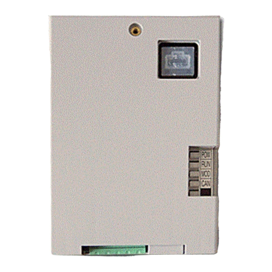
(4) The screw which fixes a facecover (M3 times 8 mm):1 (5) Bus resister(120Ω):1 If you discover any problems, contact the Hitachi inverter dealer from whom you purchased the unit immediately. 1.2 INQUIRY OF THE PRODUCT AND WARRANTY FOR THE PRODUCT 1.2.1 Request upon inquiring... - Page 6 1.3 Appearance and Names of Parts LED display Power supply(POW) Inverter Status(RUN) Inverter condition mode(MOD) CANbus Status(CAN) Bus ready (in CANopen this LED always green) Baud rate & Node ID setting(See 4.1.2) CAN bus Interface Figure 1-1 Appearance of SJ2-CO...
- Page 7 Input Restricted Version: 2=SJ200-2(L200-2) voltage distribution space=SJ200 (L200) 1.5 Specifications Label There is the Specifications Label of SJ2-CO on the back side. model name SJ2-CO MFG No. 67A T25724B6 0001 Manufacturing No. Hitachi Industrial Equipment Systems Co.,Ltd. Production time NEXXXXX...
-
Page 8: Chapter2 Mounting Method Of Option
CHAPTER 2 MOUNTING METHOD OF OPTION 2.1 Mounting method of option Please connect the following cables first, and then attach the SJ2-CO to the front cover of SJ/L200-2. [Installation step] (1) mounting location (2) Change the dipswitch position to lower ( OPE ) - Page 9 SJ2-MF labeled “OPE”. *1:The CANopen connector is connected to the bottom side of the SJ2-CO SJ2-MF Specifications Label: See 1.5 Specifications Label Figure 2-2 Installation of SJ2-CO (L200-2 + SJ2-CO + SJ2-MF) Figure 2-3 Remove of SJ2-CO (SJ200-2 + SJ2-CO)
- Page 10 All manuals and user guides at all-guides.com CHAPTER 2 MOUNTING METHOD OF OPTION SJ2-CCV (Optional) SJ2-CCV SJ200-2 OPE-SRmini HITACHI SJ2-CO SJ2-CCV SJ2-CCV Specifications Label: See 1.5 Specifications Label Figure 2-4 Installation of option unit (SJ200-2 + SJ2-CO + SJ2-CCV)
-
Page 11: Chapter3 Wiring, Connecting
WIRING, CONNECTING 3.1 Connection for CANopen connector SJ2-CO has a Pluggable open connector (Male contacts), and a Network connector (Female contacts) attached. The inverter and attach connector have a seal which is color coordinated to correspond to the network cable. Ensure the cable and contact are wired in the same color cable. - Page 12 Trunk line Multi port Tap (120Ω) Terminating Resistor (120Ω) Figure 3-2 Example of components for construction of CANopen application Note:Communication power supply(DC 24V) of SJ2-CO is not required. Please don’t make a short circuit between PIN 1(Black) and 5(Red).
-
Page 13: Chapter4 Setting
All manuals and user guides at all-guides.com CHAPTER4 SETTING 4.1 Setting methods of Baud rate and Node ID Follow the procedure below to set Baud rate in CANopen and Node ID, reset the power supply after changing the setting (setting will be reflected after resetting power supply.). Initial Baud rate: 125kbps, Initial Node ID: 2. - Page 14 Note**: CANopen Interface Option cannot detect bus-off status with heartbeat. Using P045 command, set value of P044 instead of detecting bus-off status. 4.3 Power Supply LED check If the Power Supply LED(See 1.3) is not ON ,please remount(See 2.1) the SJ2-CO unit again.
-
Page 15: Chapter5 Canopen Communication Function
All manuals and user guides at all-guides.com CHAPTER5 CANOPEN COMMUNICATION FUNCTION 5.1 Feature of CANopen communication function 5.1.1 SDO(Service Data Object) When using the segmented SDO download and upload services, the communication software will be responsible the SDO as a sequence of segments. Explicit transfer has to be supported. - Page 16 All manuals and user guides at all-guides.com CHAPTER5 CANOPEN COMMUNICATION FUNCTION 5.1.2 PDO(Process Data Object) The real-time data transfer is using the PDOs. There are two kinds of PDO transmission modes. One is a synchronization (SYNC), the other is asynchronization message (Remotely Request, Event Driven, Timer Driven). These PDO services use the push / pull models.
- Page 17 All manuals and user guides at all-guides.com CHAPTER5 CANOPEN COMMUNICATION FUNCTION 5.1.3 Device Control CAN open interface option can use "Velocity Mode" DSP-402 V2.0 drive control profile. 5.1.4 Object Dictionary for Standardized Device Profile Area CAN open interface option is supported following objects. Index Meaning Type...
- Page 18 All manuals and user guides at all-guides.com CHAPTER5 CANOPEN COMMUNICATION FUNCTION 5.1.6 Control word (Index: 6040h) The control word is used to send control commands to the inverter. (HOST-> Inverter) Description Note Mandatory Switch On-Stop Mandatory Disable Voltage-Free Run Stop Mandatory Quick stop-Stop using 2CH setting Mandatory...
- Page 19 All manuals and user guides at all-guides.com CHAPTER5 CANOPEN COMMUNICATION FUNCTION 5.1.7 Status word (Index: 6041h) The status word indicates the current state of the inverter. Description Note Ready to switch on Mandatory Switched on Mandatory Operation enabled Mandatory Fault Mandatory Voltage enabled (~V1.04) Voltage disable ->...
- Page 20 All manuals and user guides at all-guides.com CHAPTER5 CANOPEN COMMUNICATION FUNCTION 5.1.8 State Machine Power Power Power Power Disabled Disabled Disabled Disabled Start up Fault Reaction Active Not Ready to Fault Switch On Switch On Disabled Ready to Switch On Power Power Power...
- Page 21 All manuals and user guides at all-guides.com CHAPTER5 CANOPEN COMMUNICATION FUNCTION 5.1.9 Using RFG(Ramp Function Generator) Purpose of using RFG is selecting RAMP (frequency generator) sources. The method of selecting RAMP sources is using STW. It is shown diagram below. Index 1 vl_velocity_acceleration Conv.
- Page 22 All manuals and user guides at all-guides.com CHAPTER5 CANOPEN COMMUNICATION FUNCTION 5.1.10 vl_target_velocity (Index: 6042h) The vl target velocity is the required velocity of the system. It is multiplied the vl dimension factor and the vl set-point factor, if these are implemented. Inverter parameter = output frequency setting (Multi-speed0) (A020) (unit: min Minimum unit: 1dig= 1min...
- Page 23 All manuals and user guides at all-guides.com CHAPTER5 CANOPEN COMMUNICATION FUNCTION 5.1.14 vl_velocity_acceleration (Index: 6048h) The vl velocity acceleration index specifies the slope of acceleration ramp for RFG. (32bit length) It is generated as the quotient of the delta speed(Sub-index1) and delta time(sub-index2) sub- index.
- Page 24 All manuals and user guides at all-guides.com CHAPTER5 CANOPEN COMMUNICATION FUNCTION 5.1.16 modes_of_operation (Index: 6060h/6061h) The actual mode is reflected in the modes of operation display (index 6061h), and not in the mode of operation(index 6060h). But CANopen Interface Option supported only Velocity Mode. These objects are always stored “2(Velocity mode)”.
-
Page 25: Chapter6 Countermeasure For Abnormality
All manuals and user guides at all-guides.com CHAPTER6 COUNTERMEASURE FOR ABNORMALITY 6.1 Trip display When the inverter is in a tripped state, the inverter displays an error code (See table below). The trip history monitor (d081 to d086) also displays the same error code as the inverter. Trip 6.2 Protection function list The table below describes an error code for protecting the inverter and the motor. - Page 26 All manuals and user guides at all-guides.com CHAPTER6 COUNTERMEASURE FOR ABNORMALITY 6.4 LED display and Countermeasure Following states are indicated by Module LED and CANopen status LED. MOD (Module status) LED: It indicates Inverter condition. CAN (CANopen status) LED: it indicates CANopen status. Color State Countermeasure...
-
Page 27: Chapter7 Communication Objects Lists
All manuals and user guides at all-guides.com CHAPTER7 COMMUNICATION OBJECTS LISTS 7.Communication Objects Communication Objects are grouped 3 areas. Index Profile Area 1000-1FFF Communication Profile Area 2000-5FFF Manufacturer Specific Profile Area(Inverter's parameter area) 6000-9FFF Device Profile Area 7.1 Device Profile Area Supported Communication Object by CANopen interface option ( ) =initial value Index Sub-Index... - Page 28 All manuals and user guides at all-guides.com CHAPTER7 COMMUNICATION OBJECTS LISTS 7.2 Profile Manufacyure Objects (d,F group) INDEX Parameter Function Name Size Unit Note 0x2001 d001 Output frequency monitor 0.1Hz 0x2002 d002 Output current monitor 0.1% 0x2003 d003 rotation direction monitor 0x2004 d004 PID feedback monitor...
- Page 29 All manuals and user guides at all-guides.com CHAPTER7 COMMUNICATION OBJECTS LISTS 7.3 Profile Manufacture Objects (A,b,C,H,P group) INDEX Parameter Function Name Size Unit Note 0x2401 A001 Frequency source setting 0x2501 A201 Frequency source setting,2nd motor 0x2402 A002 Run command source setting 0x2502 A202 Run command source setting,2nd motor...
- Page 30 All manuals and user guides at all-guides.com CHAPTER7 COMMUNICATION OBJECTS LISTS INDEX Function Name Size Unit Parameter Note 0x2445 A045 Output voltage gain 0x2545 A245 Output voltage gain,2nd motor 0x2446 A046 I-SLV Voltage compensate gain 0x2546 A246 I-SLV Voltage compensate gain, 2nd motor 0x2447 A047 I-SLV Slip compensate gain...
- Page 31 All manuals and user guides at all-guides.com CHAPTER7 COMMUNICATION OBJECTS LISTS INDEX Parameter Function Name Size Unit Note 0x24A1 A101 OI start 0.1Hz 0x24A2 A102 OI end 0.1Hz 0x24A3 A103 OI start rate 0x24A4 A104 OI end rate 0x24A5 A105 OI start selection 0x24E1 A141...
- Page 32 All manuals and user guides at all-guides.com CHAPTER7 COMMUNICATION OBJECTS LISTS INDEX Parameter Function Name Size Unit Note 0x2691 b091 Stop mode selection 0x2692 b092 Cooling fan control 0x2695 b095 BRD selection 0x2696 b096 BRD ON level 0x26D0 b130 OV LAD STOP selection 0x26D1 b131 OVLAD STOP level...
- Page 33 All manuals and user guides at all-guides.com CHAPTER7 COMMUNICATION OBJECTS LISTS INDEX Parameter Function Name Size Unit Note 0x2877 C077 Comm. Error time 0.01sec 0x2878 C078 Communication waiting time 1.msec 0x2881 C081 O input scan calibration 0.1% 0x2882 C082 OI input scan calibration 0.1% 0x2885 C085...
-
Page 34: Chapter8 Specifications
All manuals and user guides at all-guides.com CHAPTER8 SPECIFICATIONS 8.1 CANopen Specifications of SJ200-2/L200-2 Series CANopen Option The table below describes CANopen specifications of “CANopen interface option”. Item Specifications Communication Profile DS-301 V4.01 Device Profile DS-402 V2.0 Synchronization Object (SYNC) Time Stamp Object (TIME) Emergency Object (EMCY) Network Management Object... -
Page 35: Chapter9 Contact Information
North Ryde, N.S.W.2113 Germany Australia Phone:+49-211-5283-0 Phone:+61-2-9888-4100 Fax: +49-211-5283-649 Fax: +61-2-9888-4188 Hitachi America, Ltd Hitachi Industrial Equipment System Co., Ltd Power and Industrial Division International Sales Department 50 Prospect Avenue ASK Bldg., 3,kanda Neribei-cho Tarrytown, NY 10591 Chiyodaku, Tokyo, 101-0022 U.S.A.