Table of Contents
Advertisement
Available languages
Available languages
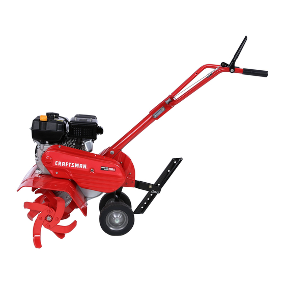
FRONT TINE TILLER
Model Nos.
CMXGVAM1144043
IF YOU HAVE QUESTIONS OR COMMENTS, CONTACT US.
SI TIENE DUDAS O COMENTARIOS, CONTÁCTENOS.
1-888-331-4569
Before using this equipment, read the manual and follow all safety rules and operating instructions.
NOTE: This Operator's Manual covers several models. Features may vary by model. Not all features in this manual are applicable to all models and the model depicted may differ
from yours.
CRAFTSMAN® is a registered trademark of Stanley Black & Decker, Inc., used under license.
CRAFTSMAN® es una marca registrada de Stanley Black & Decker, Inc., utilizada bajo licencia.
© 2018 CRAFTSMAN U.S. & Canada Only
CRAFTSMAN.com
INSTRUCTION MANUAL | MANUAL DE INSTRUCTIONES
CAUTION
WWW.CRAFTSMAN.COM
Form No. 769-17830
(September 10, 2018)
Advertisement
Chapters
Table of Contents

Related Manuals for Craftsman CMXGVAM1144043


Summary of Contents for Craftsman CMXGVAM1144043
- Page 1 NOTE: This Operator’s Manual covers several models. Features may vary by model. Not all features in this manual are applicable to all models and the model depicted may differ from yours. Form No. 769-17830 CRAFTSMAN® is a registered trademark of Stanley Black & Decker, Inc., used under license. CRAFTSMAN® es una marca registrada de Stanley Black & Decker, Inc., utilizada bajo licencia. (September 10, 2018) ©...
-
Page 2: Table Of Contents
TABLE OF CONTENTS Safety Instructions . . . . . . . . . . . . . . . . . . . . . . . . . . . . . . .Page 3 Off-Season Storage . -
Page 3: Safety Instructions
SAFETY INSTRUCTIONS WARNING DANGER This symbol points out important safety instructions which, if not This machine was built to be operated according to the safe operation followed, could endanger the personal safety and/or property of practices in this manual. As with any type of power equipment, yourself and others. - Page 4 SAFETY INSTRUCTIONS • To reduce fire hazards, keep machine free of grass, leaves, or other debris • If the machine should start making an unusual noise or vibration, stop the build-up. Clean up oil or fuel spillage and remove any fuel soaked debris. engine, disconnect the spark plug wire and ground it against the engine.
- Page 5 SAFETY INSTRUCTIONS NOTICE REGARDING EMISSIONS SPARK ARRESTOR Engines which are certified to comply with California and federal EPA WARNING emission regulations for SORE (Small Off Road Equipment) are certified to operate on regular unleaded gasoline, and may include the following This machine is equipped with an internal combustion engine and should emission control systems: Engine Modification (EM), Oxidizing Catalyst (OC), not be used on or near any unimproved forest-covered, brushcovered or...
-
Page 6: Assembly
ASSEMBLY NOTE: This unit is shipped without gasoline or oil in the engine. Be certain to service Use two clevis pins and two cotter pins from the manual bag. From the engine with gasoline and oil as instructed in the Operation section of this manual FRONT of the tiller install the inner LH tines (A1) onto the inner left side of before operating your machine. - Page 7 ASSEMBLY Wheel Assembly & Depth Stake Assembly Handle The handle is tilted down and packaged loose for shipping purposes. To attach the Remove the remaining clevis pin and cotter pin from the manual bag, install handle, proceed as follows: the wheel assembly into the chain case bracket as shown in Figure 3. Remove the bolts, washers and nuts from the chain case bracket.
- Page 8 ASSEMBLY Clutch Cable Adjustment When the handle is in place, insert the clutch cable into the cable guide on the handle as shown in Figure 7. Before operating the tiller the adjustment of the forward clutch cables must be checked. Disconnect and ground the spark plug wire against the engine.
-
Page 9: Operation
OPERATION Handle Handle Height Adjustment Depth Stake Tines Figure 10 Controls Depth stake Now that you have set up your tiller for operation, get acquainted with its controls and The depth stake controls the tilling depth. features. These are described on the next two pages and illustrated on this page. This Tines knowledge will allow you to use your new equipment to its fullest potential. - Page 10 OPERATION Operation Yoke Forward Attach the wheel yoke so that the wheels are forward (nearest to tines) for shallow tilling, Starting & Stopping the Engine cultivating and transport by removing the clevis pin and cotter pin. See Figure 11. WARNING Read, understand, and follow all the instructions and warnings posted on the machine and in this manual before operating.
- Page 11 OPERATION Clearing the Tines Depth Stake The depth stake acts as a brake for the tiller and controls the depth and speed at WARNING which the machine will operate. Remove the clevis pin and hairpin clip to raise or lower the depth stake. See Figure 13. Before clearing the tines by hand, stop the engine, allow all moving parts to stop and disconnect the spark plug wire.
- Page 12 OPERATION Choosing the Correct Tine Speed • If the garden size will not permit lengthwise and then crosswise tilling, then overlap the first passes by one-half a tiller width, followed by successive With experience, you will find the tilling depth and tilling speed combination that passes at one-quarter width.
- Page 13 OPERATION Terrace Gardening To create a terrace, start at the top of the slope and work down Go back and forth across the first row. See Figure 19. UPHILL 12" UNTILLED REPEAT DOWNHILL Figure 19 Each succeeding lower terrace is started by walking below the terrace you are preparing.
-
Page 14: Service And Maintenance
SERVICE AND MAINTENANCE MAINTENANCE SCHEDULE WARNING Follow the maintenance schedule given below. This chart describes service Before performing any type of maintenance/service, disengage all controls guidelines only. Use the Service Log column to keep track of completed and stop the engine. Wait until all moving parts have come to a complete maintenance tasks. - Page 15 SERVICE AND MAINTENANCE Tines Checking Engine Oil Check oil before each use. Stop engine and wait several minutes before checking Tilling Width oil level. With engine on level ground, the oil must be to FULL mark on dipstick. With the outer tines installed, the working width of the machine is 24”. This Service engine as instructed in the separate Engine operator’s manual.
- Page 16 SERVICE AND MAINTENANCE Belt Replacement Tine Inspection The bolo tines will wear with use and should be inspected at the beginning of Your tiller has been engineered with a belt made of special material (Kevlar Tensile) each tilling season and after every 30 operating hours. The tines can be replaced for longer life and better performance.
-
Page 17: Off-Season Storage
SERVICE AND MAINTENANCE Off-Season Storage Using a 1⁄2” wrench, remove the hex screw securing the belt keeper to the engine. See Figure 24. Preparing the Engine Engines stored between 30 and 90 days need to be treated with a gasoline stabilizer Belt Keeper and engines stored over 90 days need to be drained of fuel to prevent deterioration and gum from forming in fuel system or on essential carburetor parts. -
Page 18: Troubleshooting
TROUBLESHOOTING WARNING Before performing any type of maintenance/service, disengage all controls and stop the engine. Wait until all moving parts have come to a complete stop. Disconnect spark plug wire and ground it against the engine to prevent unintended starting. Always wear safety glasses during operation or while performing any adjustments or repairs. -
Page 19: Español
ÍNDICE Medidas importantes de seguridad . . . . . . . . . . . .Página 20 Almacenamiento fuera de temporada . . . . . . . . .Página 36 Montaje . -
Page 20: Medidas Importantes De Seguridad
INSTRUCCIONES DE SEGURIDAD ADVERTENCIA PELIGRO La presencia de este símbolo indica que se trata de instrucciones de Esta máquina está diseñada para ser utilizada respetando las normas de seguridad importantes que se deben respetar para evitar poner en seguridad contenidas en este manual. Al igual que con cualquier tipo de peligro su seguridad personal y/o material y la de otras personas. - Page 21 INSTRUCCIONES DE SEGURIDAD Manejo seguro de la gasolina: • Sea sumamente precavido cuando opere la máquina sobre una superficie con grava o al cruzarla. Manténgase alerta por si se presentan peligros ocultos o Para evitar lesiones personales y daños materiales tenga mucho cuidado al tránsito.
- Page 22 INSTRUCCIONES DE SEGURIDAD MANTENIMIENTO Y ALMACENAMIENTO AVISO REFERIDO A EMISIONES Los motores que están certificados y cumplen con las regulaciones de • Mantenga la máquina, los aditamentos y accesorios en condiciones de emisiones federales EPA y de California para SORE (Equipos Small Off Road funcionamiento seguro.
- Page 23 INSTRUCCIONES DE SEGURIDAD SÍMBOLOS DE SEGURIDAD En esta página se presentan y describen los símbolos de seguridad que pueden aparecer en este producto. Lea, entienda y cumpla todas las instrucciones incluidas en la máquina antes de intentar armarla y utilizarla. Símbolo Descripción LEA LOS MANUALES DEL OPERADOR...
-
Page 24: Montaje
MONTAJE NOTA: Esta unidad se envía sin gasolina ni aceite en el motor. Antes de operar Enganche el extremo "Z" del cable del embrague de marcha directa (A) en la la máquina cargue el motor con gasolina y aceite como se indica en la sección palanca de enganche de los dientes de marcha directa. - Page 25 MONTAJE Asegure el perno después de ajustar la traba de la manija. Vea la Figura 4. Introduzca el conjunto de la estaca de profundidad en el cuadro y volver a instalar los dos tornillos que quitó antes. Apriete los tornillos hexagonales de forma segura.
- Page 26 MONTAJE Configuración Recomendaciones Sobre el Combustible Utilice gasolina para automóviles (sin plomo o bajo contenido de plomo para minimizar El Control y la Adición de Aceite los depósitos en la cámara de combustión) con un mínimo de 87 octanos. Se puede usar gasolina con hasta un 10% de etanol o un 15% de MTBE (éter metílico terciario-butílico).
- Page 27 MONTAJE Ajustes Antes de utilizar el timón del ajuste de los cables de embrague de marcha adelante debe ser revisado. ADVERTENCIA Desconecte y conecte el cable de la bujía contra el motor. Antes de operar su cultivadora, lea atentamente y cumpla todas las Ajuste el cable del embrague de marcha adelante, aflojando la tuerca instrucciones que aparecen a continuación.
-
Page 28: Funcionamiento
FUNCIONAMIENTO Manija Ajuste de la altura de la manija Estaca de la profundidad Dientes Figura 11 Controles Estaca de profundidad Ahora que tiene la cultivadora preparada para funcionar, familiarícese con los La estaca de profundidad controla la profundidad de la labranza. controles y funciones. - Page 29 FUNCIONAMIENTO Retén Hacia Adelante Compruebe que el control del embrague de los dientes esté desenganchado y consulte el Manual de operación del motor para instrucciones sobre cómo Coloque el retén de las ruedas de manera que las ruedas estén hacia delante arrancar y detener el motor.
- Page 30 FUNCIONAMIENTO Estaca de Profundidad Los dientes tienen una acción autolimpiante que elimina la mayor parte de los desechos que se enredan. Sin embargo, a veces se pueden enredar pasto seco, tallos La estaca de profundidad funciona como un freno de la cultivadora y controla la fibrosos o enredaderas resistentes.
- Page 31 FUNCIONAMIENTO Elección de la Velocidad Correcta Para los Dientes • Cuando termine en una dirección, realice una segunda pasada en ángulo recto, vea la Figura 18. Traslape cada pasada para obtener el mejor resultado • Con experiencia, podrá encontrar la combinación de profundidad y velocidad (en terreno muy duro, puede ser necesario realizar tres o cuatro pasadas para de labranza más adecuada a las necesidades de su jardín.
- Page 32 FUNCIONAMIENTO Labranza en Pendiente El trabajo en cada terraza inferior sucesiva comienza caminando en la terraza debajo de la que está preparando. Para mayor estabilidad de la cultivadora, ADVERTENCIA siempre mantenga la rueda cuesta arriba en el suelo blando, recién labrado. No realice la labranza en las últimas 12”...
-
Page 33: Servicio Y Mantenimiento
SERVICIO Y MANTENIMIENTO PROGRAMA DE MANTENIMIENTO ADVERTENCIA Siga el programa de mantenimiento que se presenta a continuación. Esta tabla sólo Antes de realizar cualquier tipo de mantenimiento o servicio, desenganche todos describe pautas de servicio. Utilice la columna Registro de Servicio para hacer el los controles y detenga el motor. - Page 34 SERVICIO Y MANTENIMIENTO Control de la Bujía de Encendido Dientes Con los dientes exterior instalado, el ancho de trabajo de la máquina es de 24”. Esta ADVERTENCIA anchura se puede reducida a 22” por el movimiento de la horquilla y pasadores, NO pruebe la chispa si no está...
- Page 35 SERVICIO Y MANTENIMIENTO Con el uso, los dientes se hacen más cortos, estrechos y puntiagudos. Dientes muy desgastados se traducirá en una pérdida de profundidad de labranza, y la reducción Cambio de correa de la eficacia al cortar y convertir en materia orgánica. El diseño de la cultivadora incluye una correa de material especial (Kevlar Tracción) Consulte la Figura 22 para los procedimientos siguientes de púas.
-
Page 36: Almacenamiento Fuera De Temporada
SERVICIO Y MANTENIMIENTO Almacenamiento fuera de temporada El uso de un 1⁄2“ llave, retire el tornillo hexagonal de fijación del cinturón de guardián en el motor. Vea la Figura 25. Los motores almacenados entre 30 y 90 días deben tratarse con un estabilizador de gasolina y los motores almacenados durante 90 días deben drenarse para Cinturón de guardián evitar el deterioro y la formación de chicle en el sistema de combustible o en... -
Page 37: Solución De Problemas
SOLUCIÓN DE PROBLEMAS ADVERTENCIA Antes de realizar cualquier tipo de mantenimiento o servicio, desenganche todos los controles y detenga el motor. Espere a que se detengan completamente todas las piezas móviles. Desconecte el cable de la bujía y póngalo haciendo masa contra el motor para evitar que se encienda accidentalmente. Utilice siempre anteojos de seguridad durante la operación o mientras realiza ajustes o reparaciones. - Page 38 NOTES...
- Page 39 NOTES...
- Page 40 Product Manufactured by (Producto fabricado por): MTD LLC, P.O. BOX 361131 CLEVELAND, OHIO 44136-0019...