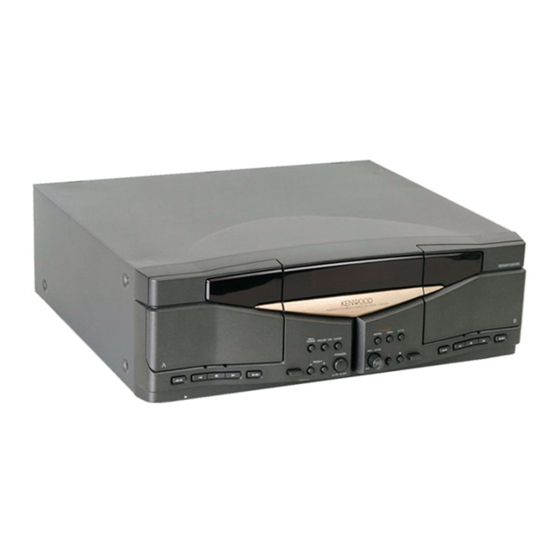
Kenwood X-W320 Service Manual
Stereo double cassette deck
Hide thumbs
Also See for X-W320:
- Instruction manual (36 pages) ,
- Service manual (17 pages) ,
- Instruction manual (37 pages)
Advertisement
Quick Links
STEREO DOUBLE CASSETTE DECK
X-W320
SERVICE MANUAL
Cassette lid ass'y
(A53-2021-08)
A
2
7
3
1
LINE
REC
PLAY
IN
OUT
L
R
Phono jack
(E11-0369-08)
All manuals and user guides at all-guides.com
Front glass
(B03-3818-08)
STEREO DOUBLE CASSETTE DECK X-W320
REV.
MODE
DOLBY NR
CCRS
POWER
RESET
0
¡
MIN
- ON – OFF
Panel
(A60-1287-08)
SYSTEM
CONTROL
AC 110 -
120V
Miniature phone jack
(E11-0188-05)
© 1997-8/B51-5348-00 (K/K) 3486
DUBBING
NORM.
HIGH
O.T.E.
REC LEVEL
8
2
0
1
MAX
Power cord bushing
(J42-0336-08)
AC 220 -
240V
Slide switch *
AC power cord *
(S90-0125-08)
(E30-)
* Refer to parts list page on 16.
Cassette lid ass'y
(A53-2022-08)
B
7
3
¡
Advertisement

Summary of Contents for Kenwood X-W320
- Page 1 All manuals and user guides at all-guides.com X-W320 SERVICE MANUAL © 1997-8/B51-5348-00 (K/K) 3486 Cassette lid ass'y Front glass Cassette lid ass'y (A53-2021-08) (B03-3818-08) (A53-2022-08) STEREO DOUBLE CASSETTE DECK X-W320 DUBBING REV. NORM. HIGH MODE O.T.E. DOLBY NR CCRS POWER...
-
Page 2: Table Of Contents
-W320 All manuals and user guides at all-guides.com CONTENTS / ACCESSORIES Contents CONTENTS / ACCESSORIES ........2 SCHEMATIC DIAGRAM ..........9 CIRCUIT DESCRIPTION ..........3 EXPLODED VIEW .............14 ADJUSTMENT .............6 PATS LIST ..............16 PC BOARD ..............7 SPECIFICATIONS ........Back cover Accessories Check that the following accessories are present. Audio cord ......(2) System control cord..(1) * AC plug adapter ...(1) -
Page 3: Circuit Description
X-W320 All manuals and user guides at all-guides.com CIRCUIT DESCRIPTION 1. Microprocessor 1-1 Microprocessor periphery block diagram REC MUTE IC 201 PB AMP LINE MUTE SYSTEM IC PLAY B/A MATRIX TAPE A B BIAS TAPE B B R/P DATA IC 101... - Page 4 -W320 All manuals and user guides at all-guides.com CIRCUIT DESCRIPTION 1-2 Pin description Pin No. Pin Name Description Action G7~G1 FL tube grid signal output (G7~G1) SUPPLY (+5V) System IC clock output System IC strobe signal input DATA System IC serial data output HXPRO HX-PRO bias switching L : ON...
- Page 5 X-W320 All manuals and user guides at all-guides.com CIRCUIT DESCRIPTION 2. Initialize When the mechanism made an irregular action, follow the chart below for initializing. Commence initializing Switch ON MTR (Wait for 1 sec.) Switch ON "PLAY" SW Switch ON SOL (50 msec.)
-
Page 6: Adjustment
-W320 All manuals and user guides at all-guides.com ADJUSTMENT INPUT OUTPUT CASSETTE TAPE ALIGNMENT ITEM ALIGN FOR FIG. SETTINGS SETTINGS DECK SETTINGS POINTS Unless otherwise specified : each ; switch should be set as follows : TAPE : NORMAL, DOLBY : OFF, INPUT : LINE 0dBs=0.775V I.Cassette mechanism section (REC/PB head adjustment) Demagnetize the REC /PB... -
Page 7: Pc Board
All manuals and user guides at all-guides.com CB/SD( 97.11.29 4:31 AM y [ W 2 PC BOARD(Component side view) Refer to the schematic diagram for the value of resistors and capacitors. - Page 8 All manuals and user guides at all-guides.com CB/SD( 97.11.29 4:32 AM y [ W 3 RECORD/PLAYBACK UNIT 13.3V +13V R301 27K R302 27K BUFFER C239 10u35 JK301 R313 R317 R307 10K PLAY:0V R305 100K REC:2.5V PLAY:0V PLAY:2.5V Q201 REC:4.2V Q303 Q305 REC:0V IC301...
- Page 9 All manuals and user guides at all-guides.com CB/SD( 97.11.29 4:32 AM y [ W 4 DISPLAY UNIT FL601 +13V +13V CNP101 4.8V R253 1.5K C227 -19.2V 0.033 C221 R126 4.5V 2200P C223 R161 R124 2200P R162 TP201 DOLBY NR R163 R261 3.3K -12.6V...
- Page 10 CNS604 STOP STOP TAPE A TAPE B X-W320(K) CAUTION: For continued safety, replace safety critical components only with DOLBY and the double-D symbol are trademarks of manufacturer's recommended parts (refer to parts list). indicates safety critical Dolby Laboratories Licensing Corporation. Noise components.
- Page 11 All manuals and user guides at all-guides.com...
- Page 12 120V~ 240V~ J701 POWER SW701 REV. DOLBY DUBBING MODE CCRS NORM. HIGH O.T.E. S604 S601 S616 S602 S605 S610 A RESET B REC LEVEL S604 S601 S616 S601 S616 S604 S601 S616 S601 S616 X-W320 S604 S601 S604 S604 S601...
-
Page 13: Audio Cord
Ref. No Parts No. Description Ref. No Parts No. Description ress Parts nation marks ress Parts nation marks X-W320 H50-2443-08 ITEM CARTON CASE A01-3504-08 METALLIC CABINET 2E,2F J02-1197-08 FOOT A53-2015-08 CASE HOLDER (L) J19-5861-08 UNIT HOLDER (7mm) A53-2016-08 CASSETTE HOLDER (R) J19-5862-08 UNIT HOLDER (12.7mm) - Page 14 All manuals and user guides at all-guides.com New Parts New Parts Parts without Parts No. are not supplied. Parts without Parts No. are not supplied. Les articles non mentionnes dans le Parts No. ne sont pas fournis. Les articles non mentionnes dans le Parts No. ne sont pas fournis. Teile ohne Parts No.
- Page 15 All manuals and user guides at all-guides.com New Parts Parts without Parts No. are not supplied. Les articles non mentionnes dans le Parts No. ne sont pas fournis. Teile ohne Parts No. werden nicht geliefert. Add- Desti- Ref. No Parts No. Description ress Parts...
- Page 16 X-W320 All manuals and user guides at all-guides.com PARTS DESCRIPTIONS...
-
Page 17: Specifications
Dolby B NR ON ..68 dB Dolby C NR ON ..75 dB (3rd, H.D., 3 %, TYPE¿tape) 1. KENWOOD follows a policy of continuous advancements in development. For this reason specifications may be changed without notice. Notes 2. The full performance may not be exhibited in an extremely cold location (under a water-freezing temperature).


