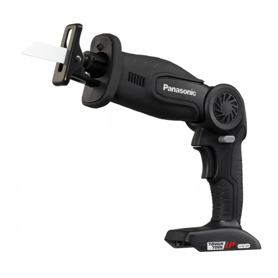
Panasonic EY47A1 Service Manual
Hide thumbs
Also See for EY47A1:
- Operating instructions manual (220 pages) ,
- Operating instructions (2 pages)
Advertisement
Quick Links
TABLE OF CONTENTS
1 Warning -------------------------------------------------------------- 2
2 Specifications ----------------------------------------------------- 2
3 Troubleshooting Guide ----------------------------------------- 3
4 Disassembly and Assembly Instructions ---------------- 5
5 Exploded View and Replacement Parts List -----------10
Cordless Reciprocating Saw
Model No.
Europe
PAGE
© Panasonic Corporation 2020. All rights reserved.
Unauthorized copying and distribution is a violation
of law.
ORDER NO. PTD2010E03CE
EY47A1
PAGE
Advertisement

Summary of Contents for Panasonic EY47A1
-
Page 1: Table Of Contents
2 Specifications ----------------------------------------------------- 2 3 Troubleshooting Guide ----------------------------------------- 3 4 Disassembly and Assembly Instructions ---------------- 5 5 Exploded View and Replacement Parts List -----------10 © Panasonic Corporation 2020. All rights reserved. Unauthorized copying and distribution is a violation of law. -
Page 2: Warning
1 Warning Caution: • Pb free solder has a higher melting point that standard solder; Typically the melting point is 50 - 70 °F (30 - 40 °C) higher. Please use a soldering iron with temperature control and adjust it to 750 ± 20 °F (400 ± 10 °C). In case of using high temperature soldering iron, please be careful not to heat too long. -
Page 3: Troubleshooting Guide
3 Troubleshooting Guide 3.1. Troubleshooting Guide... - Page 4 3.2. Trial Operation (after checking Troubleshooting Guide). 3.2.1. Assembly • Confirm if there is no gap between housing L and R by pinching lead wires. • Check the smooth movement of blade. • Slide the handle lock release lever and verify that the handle angle can be switched among its four settings. •...
-
Page 5: Disassembly And Assembly Instructions
4 Disassembly and Assembly Instructions * To reduce the risk of injury, always remove battery pack before removing/installing the tool. * To assemble the tool, start with 4-7 and proceed to 4-1. 4.1. Removing the Housing Set. 1. Remove 14 torx screws that attach housings. 2. - Page 6 4.2. Precautions when attaching the Switch. 1. Attach the trigger release flat spring into the housing like the picture and then insert the trigger lock. 2. Attach the trigger release flat spring to trigger lock. 3. Insert the Lock lever into the housing while pulling the trigger lock down.
- Page 7 4.3. Removing the Module Assembly and Connectors. Remove the module assembly from front housing and then remove the switch’s 8-pin connector and LED’s 3-pin connector from the module assembly’s control circuit board. 4.4. Removing the Gear Box Block and Associated Parts. Remove the motor assembly, gear box block, switch assembly and guard assembly from the front/back housing.
- Page 8 4.6. Removing the Motor Assembly from the Gear Box Assembly. 1. Remove two screws holding the motor using phillips screw driver. 2. Unscrew the two screws that secure the lead wires from the motor assembly and remove them from the switch assembly. 4.7.
- Page 9 4.8. Wiring and Assembly Points.
-
Page 10: Exploded View And Replacement Parts List
5 Exploded View and Replacement Parts List Model No. : EY47A1 Exploded View... - Page 11 Model No. : EY47A1 Parts List Change Safe Ref.No. Part No. Part Name & Description Quantity Remarks WEY47A1K3002 FRONT HOUSING SET WEY47A1K3101 BACK HOUSING SET WEY46A5K6301 TORX SCREW (3-14), (5PCS/PK) WEY47A1L1101 GUARD ASSEMBLY WEY47A1L0001 PROTECTIVE BOOT WEY47A1L1201 CHUCK WEY47A1L6001 TORX SCREW...


