Lenovo ThinkAgile CP Part Replacement And Component Maintenance Procedures
Hide thumbs
Also See for ThinkAgile CP:
Table of Contents
Advertisement
Quick Links
Advertisement
Table of Contents

Related Manuals for Lenovo ThinkAgile CP


Summary of Contents for Lenovo ThinkAgile CP
- Page 1 ThinkAgile CP Part Replacement and Component Maintenance Procedures...
- Page 2 ( 2018) © Copyright Lenovo .
-
Page 3: Table Of Contents
Chapter 6. Storage block maintenance procedures ..47 Chapter 1. ThinkAgile CP Overview . . . 1 Storage block maintenance procedures ..Storage block component indicators .. - Page 4 ThinkAgile CP Part Replacement and Component Maintenance Procedures...
-
Page 5: Figures
... . . switch ....DIMM installation ... . © Copyright Lenovo... - Page 6 ThinkAgile CP Part Replacement and Component Maintenance Procedures...
-
Page 7: Chapter 1. Thinkagile Cp Overview
Due to its software-defined modular architecture, the ThinkAgile CP Series platform can be scaled easily by adding more compute and storage resources independently of each other as your needs grow. Suggested... -
Page 8: Storage Block
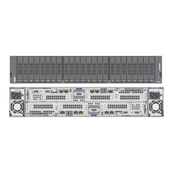
Components The ThinkAgile CP Series consists of the following components: • Storage Blocks A Storage Block is a 2U storage enclosure with up to 24 PCIe NVMe SSDs and two controllers for high availability and redundancy. A storage block runs the cloud software that delivers data storage layer to the cloud. -
Page 9: Cp Interconnect
It federates and abstracts all physical hardware into a private cloud service. Cloud Controller provides a single point of management across an unlimited number of ThinkAgile CP stacks with role-based access control, two-factor authentication, and secure HTML and RESTful API interfaces. - Page 10 ThinkAgile CP Part Replacement and Component Maintenance Procedures...
-
Page 11: Chapter 2. Roles And Responsibilities
• Lenovo Support: Works with solution administrator to perform remote support procedures The following table illustrates which roles are responsible for each of the tasks in this guide. Some tasks can be completed by the customer alone, while other tasks require the participation of Lenovo Support. Actor... - Page 12 • (Optional) Enables services Support Mode for ThinkAgile Advantage Support assistance “Shutting down the storage Powers off the storage block (all storage block” on page 53 controllers) in the Cloud Controller ThinkAgile CP Part Replacement and Component Maintenance Procedures...
-
Page 13: Interconnect
Actor Task Solution administrator Customer or field service Lenovo Support “Replacing storage Physically replaces storage network cables or controller-to-interconnect transceivers” on page 53 cable or transceiver “” on page • Obtains serial number of • Signs into primary storage controller to be... - Page 14 85 management network to other components “” on page Physically replaces management switch in the rack “Removing the Performs all steps in task management switch (optional)” on page 88 ThinkAgile CP Part Replacement and Component Maintenance Procedures...
-
Page 15: Chapter 3. Installation Guidelines
• Make sure the components that you are installing are supported by the solution. • When you install a new solution, apply the latest firmware. This will ensure that any known issues are addressed, and that your solution is ready to work with optimal performance. Contact Lenovo Support for firmware updates. -
Page 16: System Reliability Guidelines
• Remove items from your shirt pocket, such as pens and pencils, in case they fall into the solution as you lean over it. • Avoid dropping any metallic objects, such as paper clips, hairpins, or screws into the solution. ThinkAgile CP Part Replacement and Component Maintenance Procedures... -
Page 17: Handling Static-Sensitive Devices
Handling static-sensitive devices To reduce the possibility of damage from electrostatic discharge, review these guidelines before you handle static-sensitive devices. Attention: Exposure to static electricity may lead to system halt and loss of data. Prevent this problem by keeping static-sensitive components in their static-protective packages until installation, and handling these devices with an electrostatic-discharge wrist strap or other grounding system. - Page 18 ThinkAgile CP Part Replacement and Component Maintenance Procedures...
-
Page 19: Chapter 4. Managing Support Mode
Chapter 4. Managing Support Mode For a Lenovo support agent to access a customer’s ThinkAgile CP environment and provide assistance with its configuration, the customer must enable Support Mode. These topics provide information about the modifications required to ensure that Support Mode in the ThinkAgile CP interconnect switch can be enabled or disabled, as well as accessing the customer’s... -
Page 20: Access The Customer's System Via Support Mode
Step 3. After a few seconds, the interconnect switch port number and password information displays at the top of the Cloud Controller screen. The Lenovo ThinkAgile Advantage Support agent records the port number and password to use in the remote connection. - Page 21 Chapter 4 Managing Support Mode...
-
Page 22: Place A Support File On The Storage Or Compute Node
On the proxy server, create a temporary directory and copy the support file there. Step 3. Log out of the proxy server. Step 4. Use SCP to copy the firmware packages (and LLDP64e) from your laptop to the directory on the proxy server: ThinkAgile CP Part Replacement and Component Maintenance Procedures... -
Page 23: Disable Support Mode In The Cloud Controller
Step 5. Establish an SSH session with the proxy server again. Step 6. Make sure that the customer has enabled Support Mode. Step 7. Use scp to copy the files from the SSH proxy to the primary interconnect switch (in the example, the files are copied to a /tmp directory) Note: The port number used to connect to the interconnect switch is provided when the customer enables Support Mode. -
Page 24: Cloud Controller Support Mode Menu
Figure 10. Cloud Controller Support Mode menu item Step 2. A dialog box appears on screen. Click theTurn Off Support Mode button. Figure 11. Turn Off Support Mode dialog box ThinkAgile CP Part Replacement and Component Maintenance Procedures... -
Page 25: Chapter 5. Compute Block Maintenance Procedures
VM must be shut down before being migrated to another node. For best results and because of space limitations, VM owners should perform a proper shutdown within the VMs based on their application-specific shutdown procedures. © Copyright Lenovo... -
Page 26: Migrate A Vm Between Compute Nodes
When a cable is disconnected, the compute node associated with the port decreases in bandwidth by 50%. Remove a compute node This procedure describes how to remove a compute node from your ThinkAgile CP configuration. Procedure performed by: Solution administrator, ThinkAgile Advantage Support To remove a compute node from your ThinkAgile CP configuration, perform the following steps: Step 1. -
Page 27: Install A Compute Node
> > s s u u d d o o s s e e r r v v i i c c e e t t a a c c p p - - n n e e t t w w o o r r k k - - c c o o n n t t r r o o l l l l e e r r r r e e s s t t a a r r t t Step 6. Contact Lenovo Support and request a hardware removal from the database by providing the serial number and the region the hardware is (US or EU). -
Page 28: Replace The Compute Enclosure
Restore the enclosure to the rack. Drive replacement Follow these instructions to replace a front SSD in the ThinkAgile CP compute block appliance. Each ThinkAgile CP compute block appliance supports Intel 240GB solid-state drives (SSDs). These drives are used for installing the operating system and no user data are stored on these drives. These drives are used in RAID 1 mode. -
Page 29: Drive Removal
Chapter 3 “Read “ATTENTION: Static Sensitive Device Installation Ground package before Guidelines” on opening” on page 11 page 9 Before you remove a drive, ensure that you save the data on your drive (especially if it is part of a RAID array) before you remove it from the node. -
Page 30: Drive Installation
Complete the following steps to install a drive: Note: If you have only one drive, you must install it in the bay 0 (upper-left). Figure 13. Drive installation ThinkAgile CP Part Replacement and Component Maintenance Procedures... - Page 31 Step 1. Install the drive in the drive bay: Ensure that the tray handle is in the open (unlocked) position. Align the drive with the guide rails in the bay. Gently push the drive into the bay until the drive stops. Rotate the tray handle to the closed (locked) position until you hear a click.
-
Page 32: Hot-Swap Power Supply Replacement
2. First, remove power cords from outlet. 3. Attach signal cables to connectors. 3. Remove signal cables from connectors. 4. Attach power cords to outlet. 4. Remove all cables from devices. 5. Turn device ON. • S002 ThinkAgile CP Part Replacement and Component Maintenance Procedures... - Page 33 1. Disconnect the power cords and all external cables. 2. Identify the failed power supply. ThinkAgile CP Compute Block appliances contain two power supplies. Note: If the amber warning LED on the node front panel is illuminated, then a power supply unit has failed.
-
Page 34: Hot-Swap Power Supply Removal
Chapter 3 “Read “ATTENTION: Static Sensitive Device Installation Ground package before Guidelines” on opening” on page 11 page 9 To avoid possible danger, read and follow the following safety statement. • S001 ThinkAgile CP Part Replacement and Component Maintenance Procedures... - Page 35 1. Ensure that the devices you are installing are supported. For a list of supported optional devices for the solution, see http://www.lenovo.com/us/en/serverproven/ 2. Do not install two power supply units with different wattages. Related information is available from the following: •...
-
Page 36: Fan Replacement
• The amber warning LED on node front panel is off. • The green indicator light on each power supply is illuminated. Fan replacement Use the following procedures to remove and install a fan. ThinkAgile CP Part Replacement and Component Maintenance Procedures... - Page 37 Failed or failing system fans can cause the system to overheat and shut down. Replace a failed system fan as soon as possible. Attention: If the amber warning LED on the node front panel is illuminated, this means that a enclosure fan has failed.
-
Page 38: Fan Fault Leds
Complete the following steps to remove a fan. Step 1. Remove the fan. • For a 60x60x56mm fan: Squeeze the fan release latches together, and lift the fan out of the enclosure. Figure 17. 60x60x56mm fan removal ThinkAgile CP Part Replacement and Component Maintenance Procedures... - Page 39 • For an 80x80x80mm fan: 1. Carefully pull the cable out from underneath the sheet metal flange. 2. Disconnect the cable. 3. Grasp the fan and lift it out of the enclosure. Figure 18. 80x80x80mm fan removal If you are instructed to return the component or optional device, follow all packaging instructions, and use any packaging materials for shipping that are supplied to you.
- Page 40 1. Lower the fan into the socket, and push it downward until it clicks into place. 2. Connect the power cable. 3. Carefully route the cable underneath the flange and ensure that the cable is routed through the notch. ThinkAgile CP Part Replacement and Component Maintenance Procedures...
- Page 41 Note: Ensure that the cable is routed in the proper location and that no wire is stuck in the flange. Figure 20. 80x80x80mm fan installation After installing a fan, complete the following steps. 1. Reinstall the fan cover (see http://thinksystem.lenovofiles.com/help/topic/7X21/install_the_fan_cover.html 2.
-
Page 42: Eiom Replacement
Use the following procedures to remove and install the Ethernet I/O module (EIOM). The ThinkAgile CP Compute Block appliances offer connectivity to the LOM (LAN on motherboard) of each node via ports on the EIOM located at the rear of the enclosure. The top Phy maps to port one of the system LOM, the bottom Phy maps to port two of the system LOM. -
Page 43: Eiom Removal
Procedure performed by: customer or field service Complete the following steps to remove the 10GbE cage (SFP+) model EIOM: Step 1. Disconnect two cables from the EIOM. Note: Ensure that you push the release latch only when disconnecting the signal cable. Step 2. -
Page 44: Eiom Installation
• All the network ports on the EIOM are fully functional. 8. If you are instructed to return the component or optional device, follow all packaging instructions, and use any packaging materials for shipping that are supplied to you. ThinkAgile CP Part Replacement and Component Maintenance Procedures... -
Page 45: Dimm Replacement
DIMM replacement Use the following procedures to remove and install a DIMM. A node might be able to self-correct for certain memory errors. However, failed memory can lead to system degradation and should be replaced quickly. Indications of a failed DIMM are: •... -
Page 46: Dimm Removal
• When you install or remove DIMMs, the node configuration information changes. When you restart the node, the system displays a message that indicates that the memory configuration has changed. You can use the Setup utility to view the node configuration information. ThinkAgile CP Part Replacement and Component Maintenance Procedures... - Page 47 • Install higher-capacity (ranked) DIMMs first, following the population sequence for the memory mode being used. • The node supports only industry-standard double-data-rate 4 (DDR4), 2666 MT/s, PC4-21300 (single-rank or dual-rank), unbuffered or synchronous dynamic random-access memory (SDRAM) dual inline memory modules (DIMMs) with error correcting code (ECC).
-
Page 48: Location Of The Dimm Connectors On The System Board
Processor 1 installed 6, 3, 7, 2, 8, 1, 5, 4 Processor 1 and 2 installed 6, 14, 3, 11, 7, 15, 2, 10, 8, 16, 1, 9, 5, 13, 4, 12 ThinkAgile CP Part Replacement and Component Maintenance Procedures... - Page 49 Memory mirroring population sequence Table 4. DIMM installation sequence (mirror mode/lockstep mode) Number of processors Installation sequence (connectors) Processor 1 installed (6, 7), (2, 3), (8, 1) Processor 1 and 2 installed (6, 7, 14, 15), (2, 3), (10, 11), (1,8), (9, 16) If you are installing 3, 6, 9 or 12 identical DIMMs for the mirroring mode, comply with the following installation sequence to achieve the best performance.
-
Page 50: Location Of The Dimm Connectors On The
Figure 26. Location of the DIMM connectors on the system board ThinkAgile CP Part Replacement and Component Maintenance Procedures... -
Page 51: Dimm Installation
Complete the following steps to install a DIMM: Important: Before installing a memory module, make sure that you understand the required installation order, depending on whether you are implementing memory mirroring, memory rank sparing, or independent memory mode. See “Installation order” on page 42 for the required installation order. Step 1. -
Page 52: Replace The Sd530 System Board
Follow this procedure to replace the SD530 system board. Procedure performed by: Solution administrator To replace the SD530 system board from the ThinkAgile CP, perform these steps. Step 1. Get the serial number and (optional) UUID information from Lenovo Cloud Controller. -
Page 53: Chapter 6. Storage Block Maintenance Procedures
Storage block component indicators This section describes the ThinkAgile CP storage block component indicators. Before performing maintenance procedures on your ThinkAgile CP storage controller, familiarize yourself with the following indicators to identify the storage block components’ operating states. © Copyright Lenovo... -
Page 54: Enclosure Indicators
– On: the enclosure is identified – Off: the enclosure is not identified • Error/Warning LED indicator: – On: fault conditions are present – Off: the enclosure is operating under normal conditions Figure 28. Enclosure indicators ThinkAgile CP Part Replacement and Component Maintenance Procedures... -
Page 55: Drive Indicators
Drive indicators Storage drives are located in the front of the storage block. Each drive has two LED indicators: • Drive activity LED indicator: – On: drive activity is present – Off: no drive activity • Drive error/warning LED indicator: –... -
Page 56: Storage Controller Indicators
– Constant Off: the controller is operating under normal conditions • Error/Warning LED indicator: – On: fault conditions are present – Off: the controller is operating under normal conditions Figure 30. Storage controller indicators ThinkAgile CP Part Replacement and Component Maintenance Procedures... -
Page 57: Shutting Off A Storage Controller
Storage controller port indicators The Ethernet port LED indicators for the storage controllers are found on the rear of the storage block. Each Ethernet port has two LED indicators: • Activity LED indicator: – On: traffic is present on the port –... -
Page 58: Trigger Manual Storage Ha
HA event. To do this, you must simulate storage HA heartbeats between the Storage Controller service running on the active storage controller. ThinkAgile CP Part Replacement and Component Maintenance Procedures... -
Page 59: Shutting Down The Storage Block
Remove a storage controller This procedure describes how to remove a storage controller from a ThinkAgile CP configuration. Procedure performed by: Solution administrator, ThinkAgile Advantage Support Step 1. -
Page 60: Add A Storage Controller
Add a storage controller This procedure describes adding a storage controller to the ThinkAgile CP configuration, assuming a storage controller has been previously removed. Procedure performed by: Solution administrator, ThinkAgile Advantage Support Step 1. - Page 61 Procedure performed by: ThinkAgile Advantage Support To pull current FRU information before beginning the VPD reprogram process (also logged during reprogram), use the check option on the ThinkAgile CP-SB VPD tool (./thinkagile_cpsb_vpd_tool.sh check). To update the storage node VPD, follow these steps: Step 1.
-
Page 62: Hot-Swap Drive Replacement
• If one or more NVMe solid-state drives are to be removed, disable them in OS before removal. Procedure performed by: Customer or field service To remove a hot-swap drive, complete the following steps: Step 1. To open the drive tray handle, press the tab. ThinkAgile CP Part Replacement and Component Maintenance Procedures... -
Page 63: Hot-Swap Drive Removal
Figure 32. Hot-swap drive removal Step 2. Grasp the handle and slide the drive out of the drive bay. Figure 33. Hot-swap drive removal Step 3. After removing a hot-swap drive: • Install the drive filler or a new drive to cover the drive bay. See “Install a hot-swap drive” on page •... -
Page 64: Opening The Drive Tray Handle
Step 1. To open the drive tray handle, press the release tab. Figure 34. Opening the drive tray handle Step 2. Slide the drive into the drive bay until it snaps into position. ThinkAgile CP Part Replacement and Component Maintenance Procedures... -
Page 65: Sliding The Drive Into The Drive Bay
Figure 35. Sliding the drive into the drive bay Step 3. Close the drive tray handle to lock the drive in place. Step 4. Check the drive status LED to verify that the drive is operating correctly. • If the yellow drive status LED is lit continuously, that drive is faulty and must be replaced. •... -
Page 66: Hot-Swap Power Supply Replacement
The device also might have more than one power cord. To remove all electrical current from the device, ensure that all power cords are disconnected from the power source. ThinkAgile CP Part Replacement and Component Maintenance Procedures... - Page 67 S001 DANGER Electrical current from power, telephone, and communication cables is hazardous. To avoid a shock hazard: • Do not connect or disconnect any cables or perform installation, maintenance, or reconfiguration of this product during an electrical storm. • Connect all power cords to a properly wired and grounded electrical outlet. •...
-
Page 68: Hot-Swap Power Supply Removal
To remove a hot-swap power supply, complete the following steps: Step 1. Disconnect the power cord from the hot-swap power supply. Step 2. Open the handle. Figure 36. Hot-swap power supply removal (1/2) ThinkAgile CP Part Replacement and Component Maintenance Procedures... -
Page 69: Hot-Swap Power Supply Removal
Step 3. Press the release tab down, and pull the handle at the same time to slide the hot-swap power supply out of the enclosure. Figure 37. Hot-swap power supply removal (2/2) The removal of the hot-swap power supply is now complete. After removing the hot-swap drive: •... - Page 70 2. First, remove power cords from outlet. 3. Attach signal cables to connectors. 3. Remove signal cables from connectors. 4. Attach power cords to outlet. 4. Remove all cables from devices. 5. Turn device ON. ThinkAgile CP Part Replacement and Component Maintenance Procedures...
-
Page 71: Hot-Swap Power Supply Installation
Before installing a hot-swap power supply: 1. Touch the static-protective package containing the new hot-swap power supply to any unpainted surface on the outside of the storage. 2. Take the new hot-swap power supply out of the package and place it on a static-protective surface. Procedure performed by: Customer or field service To install a hot-swap power supply, complete the following steps: Step 1. -
Page 72: Hot-Swap Storage Controller Replacement
Remove a hot-swap storage controller This procedure describes how to remove a storage controller from a ThinkAgile CP configuration. Procedure performed by: Customer or field service... -
Page 73: Hot-Swap Storage Controller Removal
ThinkAgile Advantage completes the following step: Step 8. ThinkAgile Advantage gathers the relevant information, contacts Lenovo Support, and requests a hardware removal from the database by providing the serial number. After removing the storage controller: 1. -
Page 74: Hot-Swap Storage Controller Installation
Install a hot-swap storage controller This procedure explains how to add a storage controller to the ThinkAgile CP configuration, assuming a storage controller has been previously removed. Procedure performed by: Customer or field service To install a hot-swap power storage controller, complete the following steps: The Customer or field service preforms the following steps: Step 1. -
Page 75: Replace The Storage Enclosure
Step 9. ThinkAgile Advantage Support: Contact Lenovo Support and request a hardware removal from the database by providing the previous storage enclosure serial number you obtained from Lenovo Support. -
Page 76: Side Cover Removal
Figure 42. Side cover removal Step 3. Remove the M5 screws and thumbscrews on both sides used to fasten the storage enclosure. Keep the M5 screws for installing the new enclosure. ThinkAgile CP Part Replacement and Component Maintenance Procedures... -
Page 77: Screws Removal
Figure 43. Screws removal Step 4. Slide the storage enclosure out of the rack along the rails and put it in a safe, static-protective place. Figure 44. Enclosure removal from rack Chapter 6 Storage block maintenance procedures... - Page 78 • “Hot-swap power supply” on page • “Storage controllers” on page To install the ThinkAgile CP storage enclosure on the slide rails, do the following: Step 2. Remove both of the side covers on the enclosure by grasping and pulling out the bottom of each side cover, and then pulling it straight up.
-
Page 79: Removal Of Side Cover
Figure 45. Removal of side cover Step 3. Lift the enclosure and slowly place the enclosure on the rail. Chapter 6 Storage block maintenance procedures... -
Page 80: Installing The Enclosure Into The Rack
Carefully slide the enclosure into the rack along the rails until the enclosure is fully inserted. Figure 46. Installing the enclosure into the rack Step 5. Secure the enclosure with the thumbscrews and the M5 screws on the front. Figure 47. Installing screws on front of enclosure ThinkAgile CP Part Replacement and Component Maintenance Procedures... -
Page 81: Reinstalling The Side Cover
Step 6. On each side of the storage enclosure, fit the hook on the top of the side cover and push the bottom of it inward to reinstall the side cover to the storage enclosure. Figure 48. Reinstalling the side cover Step 7. - Page 82 ThinkAgile CP Part Replacement and Component Maintenance Procedures...
-
Page 83: Chapter 7. Interconnect Switch Maintenance Procedures
The interconnect switch can now be unplugged safely. Make the secondary interconnect switch the primary interconnect Procedure for making the secondary ThinkAgile CP interconnect switch into the primary interconnect. Attention: You have between 6 and 12 hours to fix the primary interconnect before you notice network connectivity problems, as that is the default lease time of the DHCP server. - Page 84 Important: This procedure can be performed only under supervision of or with help from Lenovo Support. Execution: On hardware only Performed by: Lenovo Support Background: Dual interconnect configuration (DS-V3) is active-active.
-
Page 85: Recovering From Dns Misconfiguration
If this happens, do not attempt to rerun the script v3/tacp_switch_config_v3. Important: This procedure can be performed only by Lenovo Professional Services. To recover from DNS misconfiguration, follow these steps: Update /etc/tacp/tacp_switch_resource.sh with the correct DNS IP address on both interconnect Step 1. - Page 86 Step 3. subnet 10.102.31.0 netmask 255.255.255.0 { option domain-name-servers 10.0.64.10; option routers 10.102.31.254; default-lease-time 43200; max-lease-time 43200; #Disable DHCP-HA until off rules are fixed #failover peer "failover-partner"; pool { range 10.102.31.2 10.102.31.253; ThinkAgile CP Part Replacement and Component Maintenance Procedures...
- Page 87 Step 4. Restart the DHCP server on the primary interconnect switch: > > s s u u d d o o s s e e r r v v i i c c e e i i s s c c - - d d h h c c p p - - s s e e r r v v e e r r s s t t o o p p >...
- Page 88 ThinkAgile CP Part Replacement and Component Maintenance Procedures...
-
Page 89: Chapter 8. Interconnect Parts Replacement Procedures
Chapter 8. Interconnect parts replacement procedures Procedures for replacing the Lenovo ThinkAgile CP interconnect switch. Important: Interconnect switch maintenance and replacement procedures should be performed only by Lenovo Support. For information about the terms of the warranty, visit https://datacentersupport.lenovo.com/us/en/ warrantylookup Replace the interconnect switch Procedures for replacing the Lenovo ThinkAgile CP interconnect. - Page 90 - - c c o o n n t t r r o o l l l l e e r r r r e e s s t t a a r r t t Step 5. Replace the failed interconnect switch with the new interconnect, including the cabling. See “” on page . Step 6. Power on the replacement interconnect switch. ThinkAgile CP Part Replacement and Component Maintenance Procedures...
-
Page 91: Chapter 9. Management Switch Maintenance Procedures (Optional)
If during the installation, the customer performs specific configuration within the current Management Switch, such as creating a network segmentation for the ThinkAgile CP hardware management network, this configuration needs to be ported to the newly installed Management Switch before plugging the cables back. -
Page 92: Power-Cord Retention Clip Removal
Slide the switch unit out of the rack. Step 5. Loosen and remove the M4 screws attaching the mounting bracket on each side of the switch. Figure 52. Removing mounting brackets from switch ThinkAgile CP Part Replacement and Component Maintenance Procedures... -
Page 93: Securing Switch To Rack Posts
Step 6. From the front, slide the switch into the rack at the desired height. Step 7. Secure the switch unit to the rack posts with M6 screws (item 3 in following illustration), washers (item 6), and either clip nuts (item 4) or cage nuts (item 5). Torque the screws to approximately 5.7 Nm ±... -
Page 94: Removing The Management Switch (Optional)
For information about removing the switch from other supported racks, see the appropriate section in this chapter. Note: A dedicated out-of-band management switch is required for this solution. If the Lenovo ThinkSystem NE0152T RackSwitch is not used, you must provide an out-of-band management switch with the correct configuration. -
Page 95: Power-Cord Retention Clip Removal
Procedure performed by: customer or field service To replace the NE0152T from a standard rack, complete the following steps: Step 1. If the power cord retention clip is installed, remove it: Figure 55. Power-cord retention clip removal Chapter 9 Management switch maintenance procedures (optional) -
Page 96: Releasing Switch Unit From The Rack
Loosen and remove the M4 screws attaching the mounting bracket on each side of the switch. Figure 57. Removing mounting brackets from switch Install the replacement NE0152T unit by completing the steps in “” on page . ThinkAgile CP Part Replacement and Component Maintenance Procedures...