Advertisement
OWNERS
MANUAL
Model No.
45-05082-669 (42")
45-04912-669 (50")
CAUTION:
Read Rules for
Safe Operation
and Instructions
Carefully
Husqvarna Technical Assistance 800-448-7543
PRINTED IN U.S.A.
SNOW THROWER
• Safety
• Assembly
• Operation
• Maintenance
• Parts
Service parts available 1-800-448-9282 or speedepart.com
FORM NO. 28362 rev. (09/07/18)
Advertisement
Table of Contents

Related Manuals for Husqvarna 45-05082-669


Summary of Contents for Husqvarna 45-05082-669
- Page 1 OWNERS MANUAL Model No. 45-05082-669 (42") 45-04912-669 (50") SNOW THROWER • Safety • Assembly • Operation • Maintenance CAUTION: • Parts Read Rules for Safe Operation and Instructions Carefully Husqvarna Technical Assistance 800-448-7543 Service parts available 1-800-448-9282 or speedepart.com PRINTED IN U.S.A. FORM NO. 28362 rev. (09/07/18)
-
Page 2: Table Of Contents
TABLE OF CONTENTS ACCESSORIES ...............2 SERVICE AND ADJUSTMENTS ........20 SAFETY RULES ..............3 STORAGE ..............21 FULL SIZE HARDWARE CHART .........4,5 TROUBLESHOOTING ........... 21 CARTON CONTENTS .............6 REPAIR PARTS ILLUSTRATION ......22,24,26 ASSEMBLY ..............7 REPAIR PARTS LIST ........... 23,25,26 OPERATION ..............18 SLOPE GUIDE .............. -
Page 3: Safety Rules
SAFETY Read and understand the operating instructions before using. Keep the area of operation clear of all persons, especially small children and pets. Thoroughly inspect the area to be cleared and remove all door mats, sleds, boards, wires and other foreign objects. Use extreme caution when operating on or crossing gravel surfaces. Never direct discharge at bystanders or allow anyone in front of the snow thrower. 184045 199682 199683 Do not place hands near rotating parts. Keep clear of the Do not place feet near rotating parts. discharge opening at all times. • Never allow children to operate the equipment. • Take all possible precautions when leaving the unit • Never allow adults to operate the equipment without unattended. Disengage the attachment clutch lever or proper instruction. switch, lower the snow thrower, shift into neutral, set • Disengage all clutches and shift into neutral before the parking brake, stop the engine and remove the key. -
Page 4: Full Size Hardware Chart
HARDWARE PACKAGE CONTENTS ATTENTION: The hardware bags may contain some bolts and nuts which do not appear on this page or the following page. Those bolts and nuts will not be needed for the assembly of your snow thrower. SHOWN ACTUAL SIZE 43182 47630 48106 43661 43063 43768 42849 43080 43350 44326 46938 43682 44215 43088 44695 43081 43070 R19172410 43003 43082 43015 42210 47810 47572 47598... - Page 5 NOT SHOWN ACTUAL SIZE 46959 47134 27810 43055 27809 23727 25780 42842 44062 43343 43038 726-0178 46963 47788 HA9822 42991 42995 IMPORTANT: Not all items supplied in the hardware bags will be needed for your particular tractor. Unneeded items may be discarded after you have completed assembly and checked operation of unit. DO NOT DISCARD the two spare shear bolts (F) and 5/16" nylock nuts (V). Refer to the Service and Adjustments section on page 20. REF. QTY. DESCRIPTION REF. QTY. DESCRIPTION Hex Bolt, 3/8" x 3-1/4" Nylock Jam Nut, 3/8"...
-
Page 6: Carton Contents
CARTON CONTENTS Housing Assembly 11. Clutch Idler Assembly Chute Crank Rod Assembly 12. Cable Bracket Support Tube, Crank Rod 13. L.H. Hanger Bracket Winch Assembly 14. R.H. Hanger Bracket Anti-rotation Bracket. Pulley Front Pulley Frame Bracket (2) 16. Chute and Control Cable Assembly Rear Pulley Frame Bracket (2) Right Hand Side Plate V-Belt, Drive 56" (#48138) Left Hand Side Plate V-Belt, Drive (Attached to Housing Assembly) Wire Harness V-Belt, Auger, Drive 55" (#46989) 27509 27016 25728... -
Page 7: Assembly
ASSEMBLY TOOLS REQUIRED FOR ASSEMBLY ATTACHING PARTS TO TRACTOR FRAME (2) 7/16" Wrenches STEP 1: (SEE FIGURE 1) (2) 1/2" Wrenches • Align the Winch Assembly with the front of the tractor (2) 9/16" Wrenches frame. Install three 3/8" x 1" carriage bolts in the front (1) 3/4" Wrench three holes in the right side of the tractor frame. Do (1) Knife not install nuts. • Install a 5/16" x 1" carriage bolt in the fourth hole in the right side of the tractor frame. Do not install nut. REMOVAL OF PARTS FROM CARTON • Remove all loose parts, parts bags and hardware bags from the carton. Lay out and identify parts and... - Page 8 ATTACHING WIRING TO TRACTOR FRAME STEP 3: (SEE FIGURE 3) • Install a hex head shoulder bolt, a 3/8" washer and a STEP 5: (SEE FIGURE 5) 3/8" flanged lock nut in the R.H. and L.H. Side Plates. • Remove the two screws in the right side of the plastic dash housing. • Attach the on/off switch to the side of the plastic dash LH. SIDE PLATE housing, using the two screws. STEP 6: (SEE FIGURE 5) FRONT MOUNTED BATTERY ONLY • Position the wire harness relay box against the front of the battery tray on the right hand side. Attach it to the R.H.
- Page 9 STEP 8: (SEE FIGURE 6) INSTALL HANGER BRACKETS AND SHOULDER • Route the wire harness along the left side of the tractor. BOLTS TO OUTSIDE OF FRAME • Install two clamps onto the wire harness and attach them to the bolts in the top cover of the winch using STEP 11: (SEE FIGURE 9) two 5/16" nylock nuts. • Remove the bolt, if present, in the hole directly behind the brake rod on the left side of the tractor frame. 5/16" NYLOCK NUTS • Attach the L.H. Hanger Bracket (tube facing out) to the hole using a 5/16" x 3/4" self threading bolt. • Install a shoulder bolt into the hole that is 9-1/2" to the rear of the bolt you just installed. Secure it with a 3/8" flange nut on the inside of the frame. BRAKE ROD CLAMPS 5/16"...
- Page 10 THIS SECTION IS FOR TRACTORS WITH A STEP 15: (SEE FIGURE 13) • Attach each rear pulley frame bracket to the inside of MANUAL ATTACHMENT CLUTCH the clutch/idler assembly using two 5/16" x 3/4" hex If your tractor has an electric attachment clutch go to bolts, 5/16" washers and 5/16" nylock nuts. step 18 on page 12. • Attach each front pulley frame bracket to the inside STEP 13: (SEE FIGURE 11) of the clutch/idler assembly using two 5/16" x 1" hex • Attach the pulley (long end of hub facing down) and bolts, four 5/16" washers and two 5/16" nylock nuts.
- Page 11 STEP 17: (SEE FIGURE 15) 1/8" HAIRPIN PIVOT LOCK PIN NYLON TIE • Find the cable clip that is attached to the left side COTTER (use this hole) of the tractor frame underneath the footrest. Open the clip and remove the mower clutch cable. Do not L.H. HANGER SHOULDER remove the clip from the tractor frame. The cable BRACKET BOLT reattaches to the clip when using the mower deck. • Move the attachment clutch lever on the dash panel to the disengaged position. • Place the clutch/idler assembly on the floor on the left side of the tractor. • Attach the tractor's mower clutch cable to the cable MOWER bracket on the clutch/idler assembly. Secure the cable CLUTCH...
- Page 12 THIS SECTION IS FOR TRACTORS WITH AN STEP 22: (SEE FIGURE 20) ELECTRIC ATTACHMENT CLUTCH • Attach each rear pulley frame bracket to the inside of the clutch/idler assembly using two 5/16" x 3/4" hex STEP 20: (SEE FIGURE 18) bolts, 5/16" washers and 5/16" nylock nuts. • Turn the clutch idler assembly upside down. • Attach each front pulley frame bracket to the inside • Hook the long end of the spring onto the end of the of the clutch/idler assembly using two 5/16" x 1" hex bolt that extends through the nut on the bottom of the bolts, four 5/16" washers and two 5/16" nylock nuts. upper idler arm. Install a 3/8" hex lock nut onto the bolt, leaving enough space for the spring to pivot. 5/16" x 1" HEX BOLT (2) 5/16"...
- Page 13 STEP 24: (SEE FIGURE 22) STEP 25: (SEE FIGURE 23) • Attach the clutch/idler assembly to the tractor frame. • Assemble the drive belt onto the engine pulley. You Hook the notched rear pulley frame brackets onto the may need to remove the belt from the large pulley on two shoulder bolts assembled to the outside of the the clutch/idler assembly in order to assemble it onto tractor frame. Lift the front of the assembly and attach the engine pulley. When re-assembling the belt onto it to the R.H. and L.H. hanger brackets using two pivot the large pulley, be sure the belt is between the large lock pins and 1/8" hairpin cotters. pulley and the hex bolt next to it. • Place tension on the belt by pulling the left side tensioning chain out as far as the 3/32" hairpin cotter that was installed in the chain in step 19 will allow. PIVOT LOCK PIN L.H.
- Page 14 STEP 26: (SEE FIGURE 24) STEP 28: (SEE FIGURE 26) • Remove the nylon tie which fastens the chute crank • Attach the chute crank rod assembly brackets to rod to the crank rod support tube. the plastic bracket on the left side of the discharge • Assemble the crank rod support tube to the bracket on housing. Align the chute crank bracket beneath the the left side of the discharge housing using two 5/16" rod support bracket and assemble both to the plastic x 1-1/4" carriage bolts, and 5/16" Nylock nuts. bracket using two 5/16" x 1" carriage bolts, 5/16" washers and 5/16" Nylock nuts. Do not tighten yet. DISCHARGE HOUSING 5/16" x 1" CHUTE CRANK CARRIAGE BOLT BRACKET...
- Page 15 ATTACHING SNOW THROWER TO TRACTOR STEP 29: (SEE FIGURE 27) • Coat the top of the ring around the discharge opening with general purpose grease. STEP 30: (SEE FIGURE 28) • Place the discharge chute (facing forward) onto the • Place the snow thrower on a flat, level surface. ring. Place the anti-rotation bracket on top of the chute • Extend the auger belt out behind the snow thrower, flange, aligning it with the holes on the right hand side leaving the belt assembled to the snow thrower pulleys. of the flange. Attach the three chute spacers and chute • Roll the tractor up behind the snow thrower, centering keepers to the bottom of the flange using six 1/4" x 1" it between the snow thrower's mounting plates. hex bolts, 1/4" flat washers and 1/4" flanged lock nuts. • Lift up on the crank rod support tube to raise the Tighten carefully so that the nuts are snug but do not rear of the snow thrower and align the notches in the dig into the plastic chute keepers.
- Page 16 STEP 32: (SEE FIGURE 30) INSTALLING THE AUGER BELT • Remove the plastic tie from the cable. • Place the winch cable loop between the lift links and STEP 34: (SEE FIGURE 32) install a 1/2" x 1" clevis pin through the lift links and • Swing the lower idler arm over to the left side. the cable loop from the side shown. Secure it with a • Slightly loosen the belt keeper bolts located beside 5/64" hairpin cotter. the idler arm V-pulley and the rear V-pulley. • Place the auger belt around the rear V-pulley and between the two pulleys on the idler arm. The "V" side of the belt must be seated in the grooves of the V-pulleys. • Retighten the two keeper bolts. 5/64" HAIRPIN COTTER LEFT SIDE WINCH CABLE OF TRACTOR LIFT LINK...
- Page 17 SETTING THE AUGER BELT TENSION ATTACH REFLECTORS TO REAR FENDER STEP 35: (SEE FIGURE 33) STEP 37: (SEE FIGURE 35) • Pull the tensioning chain until it is extended out as far • If your tractor is not equipped with rear reflectors, as the 3/32" hairpin cotter installed in the chain will assemble the supplied rear reflectors to the rear allow. Install a 1/8" hairpin cotter through the chain to fender. Place the reflectors as close to the bottom of secure it in the extended position.
-
Page 18: Operation
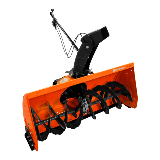
OPERATION KNOW YOUR SNOW THROWER Read this owner's manual and safety rules before operating your snow thrower. Compare the illustration below with your snow thrower to familiarize yourself with the various controls and their locations. CHUTE TILT HANDLE ON/OFF SWITCH UPPER CHUTE CRANK ROD LOWER CHUTE SCRAPER PLATE SKID SHOE SPIRAL AUGERS, R.H. & L.H. SCRAPER PLATE Replaceable plate that absorbs CHUTE TILT HANDLE Pivots the Upper Chute up or down to control the angle and distance of discharge. -
Page 19: Maintenance
• In extremely deep snow, raise the snow thrower up RAISING AND LOWERING to the transport position to remove the top layer of • Use the on/off switch attached to the side of the snow. Drive forward only until the front tires reach the tractor's dash to raise or lower the snow thrower. The uncleared bottom layer of snow. Stop and allow the winch motor will shut off when the snow thrower is in snow to clear out of the spiral auger. Back up and either the up or down position. then lower the snow thrower to the ground. Drive the tractor forward until the snow again becomes too CAUTION : Do not operate the snow deep. -
Page 20: Service And Adjustments
SERVICE AND ADJUSTMENTS CAUTION : Before servicing or adjusting the snow thrower, shut off the engine, remove SHEAR BOLT AND the spark plug wire(s), set the parking brake HEX LOCK NUT and remove the key from the tractor ignition. REPLACING AUGER BELT • Disengage the tractor's attachment clutch. • Lower the snow thrower to the ground. • Release the spring tension from the auger belt idler arm on the bottom of the clutch/idler assembly. • Remove the auger drive belt from the clutch/idler assembly and from the spiral auger housing. SCRAPER PLATE GEAR HOUSING SKID SHOE • Install new belt over top of large auger drive pulley and under the two side idler pulleys. Twist the belt 1/4 turn to seat the "V" of the belt in the groove of each FIGURE 37 idler pulley. -
Page 21: Storage
STORAGE PARTS TO REMOVE AT END OF SEASON STORAGE RECOMMENDATIONS • Lower the snow thrower to the ground. • Remove the clutch/idler assembly. (The two hanger • Remove the snow thrower from the tractor. brackets and the two shoulder bolts may be left attached to the tractor frame.) • Clean the snow thrower thoroughly. Wash off any salt • Remove the drive belt from the engine pulley. deposit which may have dried on the thrower and • If a front mounted attachment is to be used, remove housing. • Any bare metal that has become exposed should be the side plates and the winch and bracket assembly painted or coated with a light oil to prevent rust. from the tractor. Be sure to re-install any bolts that were removed from the tractor frame when the snow • Store in a dry place. - Page 22 PARTS REPAIR PARTS FOR MODELS 45-5082-669 42" & 45-04912-669 50" SNOW THROWERS...
- Page 23 REPAIR PARTS FOR MODELS 45-5082-669 42" & 45-04912-669 50" SNOW THROWERS PART NO QTY DESCRIPTION PART NO QTY DESCRIPTION 41620 Chute, Upper 43661 Hex Bolt, 1/4-20 x 1" 41621 Chute, Lower 44950 Carriage Bolt, 1/4-20 x 3/4" 27505 Chute Adapter 47630 Bolt, Self-Tap 5/16"...
- Page 24 REPAIR PARTS FOR MODELS 45-5082-669 42" & 45-04912-669 50" SNOW THROWERS 44 63...
- Page 25 REPAIR PARTS FOR MODELS 45-5082-669 42" & 45-04912-669 50" SNOW THROWERS PART NO DESCRIPTION PART NO DESCRIPTION 68846 Lift Shaft Assembly 43070 Washer, 3/8" 41616 Hex Bolt, 1/2-13 x 1" 68225 Assembly, Chute Crank Rod 41614 Hex Bolt, 5/8-11 x 1-1/2" 27585 Handle, Chute Tilt 42842 Pin, Clevis 1/2"...
- Page 26 REPAIR PARTS FOR MODELS 45-5082-669 42" & 45-04912-669 50" SNOW THROWERS PART NO QTY DESCRIPTION 26943 Frame, Clutch and Pulley 63904 Idler Arm Assembly 24286 Spacer, Pivot 63762 Idler Bracket Assembly 43015 Hex Nut, 3/8-16 46981 Pulley, V Type 9" 43082 Nut, Hex Lock, 3/8-16 46982 Pulley, V Type 5-1/2" 27582 Shaft 42830...
-
Page 27: Slope Guide
SLOPE GUIDE (Keep this sheet in a safe place for future reference.) Use this guide to determine if a slope is safe for the operation of your tractor and snow thrower. Refer also to the instructions in your vehicle owners manual. - Page 28 Service parts available 1-800-448-9282 or speedepart.com © 2012 Agri-Fab, Inc.