
Related Manuals for ABB LD 800HSE


Summary of Contents for ABB LD 800HSE
- Page 1 Device Management FOUNDATION Fieldbus Linking Device, LD 800HSE and LD 800HSE EX, V3.6.0/0 Power and productivity for a better world...
- Page 3 Device Management FOUNDATION Fieldbus Linking Device, LD 800HSE and LD 800HSE EX, V3.6.0/0...
- Page 4 In no event shall ABB be liable for direct, indirect, special, incidental or consequential damages of any nature or kind arising from the use of this document, nor shall ABB be liable for incidental or consequential damages arising from use of any software or hard- ware described in this document.
-
Page 5: Table Of Contents
Table of Contents About this User Manual User Manual Conventions ....................11 Warning, Caution, Information, and Tip Icons ............11 Terminology........................12 Released User Manuals and Release Notes..............13 Section 1 - Introduction Features of the Linking Device ..................15 Integration into the Industrial IT System Structure ............18 New in This Release ......................20 Prerequisites and Requirements ..................20 Product Support .......................20... - Page 6 Table of Contents Display Elements ....................32 Device Status Indication ..............33 Status Indications of the four H1 Channels ........42 Commissioning the Hardware..................44 Replacing a Defective Linking Device in a Redundant Set of Linking Devices .... 45 Adding a Second Linking Device to form a Redundant Set of Linking Devices ... 46 Section 3 - Configuration Communication Settings ....................
- Page 7 Table of Contents Clearing the Log Files .................90 Clearing the Error Buffer ..............91 Statistic Information................92 Internal Device Information ..............93 Appendix B - Limits and Performance Data Limits of the Linking Device on HSE ................97 Maximum Limits....................97 Performance of HSE communication..............97 Limits per H1 Channel ....................98 General Maximum Limits ..................98 Performance ......................99...
- Page 8 Table of Contents General Requirements ....................125 Commissioning and Installation..................126 Linking Device Usage ....................128 Maintenance and Repair....................129 Appendix E - Glossary Revision History Updates in Revision Index - ..................133 Updates in Revision Index A..................134 3BDD011677-600 A...
- Page 9 Installation in Hazardous Locations For general requirements on installation, rules for installing, commissioning, maintaining and the appropriate use of LD 800HSE EX in hazardous atmospheres, See page 25 and See page 125. The present manual does not supersede the relevant national regulations, standards and directives.
- Page 10 Safety Summary (continued) SPECIFIC In a redundant set of linking devices, removing the power supply, the CAUTIONS Ethernet cable from the Primary Device causes a redundancy change- over. Before doing so, make sure that the Secondary Device is opera- tional (and not still booting due to a prior change-over). Otherwise the system breaks down or the configuration information might get lost.
-
Page 11: About This User Manual
(LD 800HSE) and for hazardous areas (LD 800HSE EX). The configuration, handling, and functionality is same for both versions. Hence, they are commonly referred to as LD 800HSE throughout this manual. In case of specific considerations for hazardous areas LD 800HSE EX is explicitly stated. -
Page 12: Terminology
Webster’s Dictionary of Computer Terms. The following is a list of terms associated with the FOUNDATION Fieldbus Linking Device LD 800HSE that you should be familiar with. The list contains 3BDD011677-600 A... -
Page 13: Released User Manuals And Release Notes
About this User Manual Released User Manuals and Release Notes terms and abbreviations that are unique to ABB or have a usage or definition that is different from standard industry usage. Term Description FOUNDATION Fieldbus FOUNDATION fieldbus is a bi-directional communications protocol used for communications among field instrumentation and control systems. - Page 14 Device LD 800HSE types of product information for the linking device LD 800HSE. It describes known software or 3BDD011679 documentation problems and errors that were discovered at too late a date to be included in the current user instructions.
-
Page 15: Section 1 Introduction
HSE subnet. Features of the Linking Device The LD 800HSE is a gateway between an FF High Speed Ethernet (FF-HSE) subnet and FF-H1 links. It supports device redundancy. The linking device is registered as class 42c of the HSE profile, therefore providing the following functions: •... - Page 16 Features of the Linking Device Section 1 Introduction • Distribution of alarms and events sent by H1 devices Figure 1. Linking Device Communication Functionality in the HSE subnet: • System Management Agent • Network Management Agent • Server providing object access to H1 devices •...
- Page 17 Section 1 Introduction Features of the Linking Device Functionality in the H1 links: • System Management Manager • Network Management Manager • Client for object access • Publisher and Subscriber of process data • Reception of alarms and events • Link Master, SM Time Publisher Write access to the H1 NMA VFD of an H1 interface from an H1 link (e.g.
-
Page 18: Integration Into The Industrial It System Structure
HSE protocol and subsidiary H1 links. As a device registered as a class 42c device of the HSE profile the LD 800HSE allows process data that are being published cyclically on the subsidiary H1 links to be republished on the HSE subnet. - Page 19 Section 1 Introduction Integration into the Industrial IT System Structure Figure 2. Sample System Structure with FF Network Within a typical Industrial IT system structure the FOUNDATION Fieldbus subsystem is interfaced to the IEC 61131 controller using the communication interface module CI 860 in the AC 800M which acts as HSE host on the HSE subnet.
-
Page 20: New In This Release
Increase in security of linking device - Linking Device web server is password protected and must be changed from the default password. • Zone 2 Environment - Support of Linking device type LD 800HSE EX on Zone 2 Explosion and Protection Environment. Prerequisites and Requirements Before commissioning of LD 800HSE make sure to use the latest linking device firmware released for your system environment. -
Page 21: Section 2 Hardware Installation
Refer to the LD 800HSE and LD 800HSE EX Version Table (3BDS009910) in the ABB SolutionsBank to find out the latest linking device firmware released for your system environment. - Page 22 Do not use LD 800HSE with different article numbers within a redundant set of devices during normal plant operation. Do not online replace a redundant set of device type LD 800HSE of hardware version 1.1y by devices of hardware version 1.0x (hardware downgrade).
-
Page 23: Mounting And Dismounting
Section 2 Hardware Installation Mounting and Dismounting Mounting and Dismounting For installation on a DIN rail (35mm), the two upper notches must be attached to the rail. Press the linking device down towards the rail until it locks into place. Figure 3. - Page 24 • Mounting direction must be placed horizontally. • Clearance between the linking device and the adjacent components or side walls of the housing must be adhered as illustrated in Figure Figure 4. Field Housing with LD 800HSE Clearances 3BDD011677-600 A...
-
Page 25: Installation In Hazardous Locations
Hazardous Location - North American Approval (cULus) If indicated on the device label linking device LD 800HSE EX is suitable for use in Class 1, Division 2, Groups A, B, C and D or non-hazardous locations. -
Page 26: Hazardous Location - European And International Approval (Atex, Iecex)
ATEX marking for explosion protection: II 3G nA IIC T4 Gc The linking device LD 800HSE EX complies with the applicable standards and regulations, and meets the requirements of Directive 94/4EC. The requirements for erecting the device as part of the system in potentially explosive atmospheres (e.g. -
Page 27: Interfaces And Display Elements
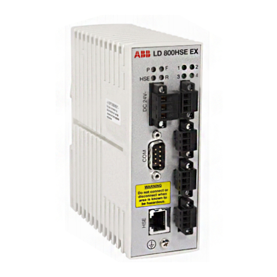
Section 2 Hardware Installation Interfaces and Display Elements Interfaces and Display Elements Figure 5. Overview interfaces and display elements Interfaces Power Supply The supply voltage (24V DC ± 20%) is connected by a 3-pole terminal block. Wire diameter: 0.2 – 2.5 mm , AWG 24-12 3BDD011677-600 A... -
Page 28: Grounding
Interfaces Section 2 Hardware Installation Replacement parts for the terminal block can be obtained from PHOENIX CONTACT (http://www.phoenixcontact.com), type MSTB 2,5/3-STF. Figure 6. Pin assignment of the terminal block for power supply Grounding A separate screw connection is available for grounding at the bottom part of the front panel. -
Page 29: 10/100 Mbit/S Ethernet Port (Hse High Speed Ethernet Port)
Section 2 Hardware Installation Interfaces The maximum cable length is 3 m according to EMC requirements. The baud rate is pre-configured to 115.2 kbit/s. Table 2. Pin assignment of the serial interface Signal When using two linking devices as a redundant set, the serial interfaces of both linking devices must be connected by a null modem cable (Article No: 3BDH000281R1), thus forming a “redundancy link”. -
Page 30: Ff H1 Fieldbus Connection
Interfaces Section 2 Hardware Installation Table 3. Pin assignment of the 10/100 Mbit/s port Not used Not used Not used Not used Figure 7. Schematic representation of the 10/100 Mbit/s Ethernet port FF H1 Fieldbus Connection With 3-pole terminal blocks, up to 4 separate fieldbus links can be connected. The FF-H1 interfaces comply with type 114 of the FF physical layer profile, which is characterized by •... - Page 31 Section 2 Hardware Installation Interfaces Wire diameter: 0.14 - 1.5 mm , AWG 28-16 Replacement parts for the terminal block can be obtained from PHOENIX CONTACT (http://www.phoenixcontact.com) as part type MC 1,5/3-STF-3,81. Figure 8. Pin assignment 3-pole terminal block for FF-H1 connections 3BDD011677-600 A...
-
Page 32: Display Elements
Display Elements Section 2 Hardware Installation Display Elements On the front of the linking device there are four LEDs (P - Power Supply, HSE - Ethernet Port, F - Error Status, R - Ready) indicating the device status and another four LEDs (1, 2, 3, 4) indicating the statuses of the four H1 links. -
Page 33: Device Status Indication
Section 2 Hardware Installation Display Elements Device Status Indication The device status indication depends on the hardware version of the LD Base Module. To allow enhanced device status indication newer hardware is equipped with two-colored F- and R-LEDs. refer to Table 5 to find out, which device status indication applies to your hardware. - Page 34 Display Elements Section 2 Hardware Installation Device Status Indication (Single-colored LEDs) Table 6. Device Status Indication with Single-colored LEDs Display Description Element P - Power Supply No supply voltage. green Supply voltage is present. HSE - Ethernet Port No Ethernet link established. green Ethernet link has been established (10 Mbit/s or 100 Mbit/s).
- Page 35 Section 2 Hardware Installation Display Elements Table 6. Device Status Indication with Single-colored LEDs Display Description Element Start-up phase (approx. 25 seconds). During this phase the power-on self tests are executed and the redundancy role is determined. Secondary Device, not ready. The device is acting as Secondary Device in a redundant set, but it is not ready to take over the primary role due to e.
- Page 36 Display Elements Section 2 Hardware Installation Table 6. Device Status Indication with Single-colored LEDs Display Description Element Primary Device or non-redundant device, hardware failure. The device is acting as Primary Device in a redundant set or as green non-redundant device, but a minor hardware failure has been detected during start-up.
- Page 37 Section 2 Hardware Installation Display Elements Device Status Indication (Two-colored F-LEDs) Table 7. Device Status Indication with Two-colored F-LEDs Display Description Element P - Power Supply No supply voltage. green Supply voltage is present. HSE - Ethernet Port No Ethernet link established. green Ethernet link has been established (10 Mbit/s or 100 Mbit/s).
- Page 38 Display Elements Section 2 Hardware Installation Table 7. Device Status Indication with Two-colored F-LEDs Display Description Element Primary Device or non-redundant device, failure. The device is acting as Primary Device in a redundant set or as green non-redundant device, but a failure has been detected. In the case of a Primary Device in a redundant set, the Secondary Device is not ready.
- Page 39 Section 2 Hardware Installation Display Elements Table 7. Device Status Indication with Two-colored F-LEDs Display Description Element Secondary Device, hardware failure. The device is acting as Secondary Device in a redundant set, but a hardware failure has been detected. Details are available on the web page /Information/Hardware Diagnostics of the device, refer to Hardware Diagnostics...
- Page 40 Display Elements Section 2 Hardware Installation Device Status Indication (Two-colored F- and R-LEDs) Table 8. Device Status Indication with Two-colored F- and R-LEDs Display Description Element P - Power Supply No supply voltage. green Supply voltage is present. HSE - Ethernet Port No Ethernet link established.
- Page 41 Section 2 Hardware Installation Display Elements Table 8. Device Status Indication with Two-colored F- and R-LEDs Display Description Element Primary Device or non-redundant device, failure. The device is acting as Primary Device in a redundant set or as green non-redundant device, but a failure has been detected. In the case of a Primary Device in a redundant set, the Secondary Device is not ready.
-
Page 42: Status Indications Of The Four H1 Channels
Display Elements Section 2 Hardware Installation Table 8. Device Status Indication with Two-colored F- and R-LEDs Display Description Element Inactive device, duplicate H1 address. The device is inactive on HSE and affected H1 links, because a device with the H1 address of the linking device has been detected on at least one H1 link during startup. - Page 43 Section 2 Hardware Installation Display Elements Table 9. Status Indication of H1 Channels Display Description Element green Device is in logical token ring but does not act as LAS on channel H1-3 (FF 3). Channel H1-3 (FF 3) is not configured. Status of H1 Channel 4 green Device acts as Link Active Scheduler (LAS) on channel H1-4 (FF 4).
-
Page 44: Commissioning The Hardware
Commissioning the Hardware Section 2 Hardware Installation Commissioning the Hardware For commissioning the hardware, perform the following steps: Connect the H1 links to the terminal blocks of the H1 interfaces. Since the linking device does not provide power to the H1 links, a power supply, a power conditioner and a bus termination is required for each H1 link. -
Page 45: Replacing A Defective Linking Device In A Redundant Set Of Linking Devices
Section 2 Hardware InstallationReplacing a Defective Linking Device in a Redundant Set of Linking Replacing a Defective Linking Device in a Redundant Set of Linking Devices For replacing a defective linking device in a redundant set of linking devices, perform the following steps: Identify the defective linking device, refer to Display Elements on page 32. -
Page 46: Adding A Second Linking Device To Form A Redundant Set Of Linking Devices
Adding a Second Linking Device to form a Redundant Set of Linking Devices Section 2 Hardware Adding a Second Linking Device to form a Redundant Set of Linking Devices For adding a second linking device to an already commissioned linking device that is operating in the role “Primary, no backup”, the following steps are required: Set the IP configuration (IP address and subnet mask) of the second linking device in a way that it is in the same IP subnet as the Primary Device. -
Page 47: Section 3 Configuration
Table 10 shows the pre-configured IP settings of the linking device. Table 10. Pre-configured IP Settings Parameter Name Pre-configured value Remark Host Name LD 800HSE not used; you may leave this unchanged or empty IP Address 192.168.1.20 mandatory Subnet Mask 255.255.255.0... - Page 48 Each LD 800HSE sends messages to IP address 224.0.0.33 cyclically every 15 seconds. In case the IP configuration of LD 800HSE is not known and a serial connection cable is not available, you could capture its ethernet traffic with a network monitoring tool (e.g.
- Page 49 Section 3 Configuration Communication Settings Table 11 shows the possible configuration functions depending on the interface that is used. Those functions available via web browser (HTTP protocol) will be explained in detail in the following subsections. Table 11. Configuration Functions and Interfaces Type of connection protocol HTTP Serial...
-
Page 50: Setting Up An Ip Connection Between Pc And Linking Device
Setting Up an IP Connection between PC and Linking Device Section 3 Configuration Setting Up an IP Connection between PC and Linking Device The linking device is delivered with the pre-configured IP address 192.168.1.20. Connect the linking device to your PC. For a direct connection, a cross-linking cable must be used. - Page 51 Section 3 Configuration Setting Up an IP Connection between PC and Linking Device Step 2: Configure your PC in such a way that you have access to the network 192.168.1.0. For this purpose, you may have to assign your PC a second IP address (e.g.
-
Page 52: Assignment Of A Second (Local) Ip Address
Setting Up an IP Connection between PC and Linking Device Section 3 Configuration Assignment of a Second (Local) IP Address This subsection describes how to assign a second IP address to a PC running on the latest supporting operation system. For other operating systems, refer to the corresponding instructions manual or to the online help of the operating system used. - Page 53 Section 3 Configuration Setting Up an IP Connection between PC and Linking Device • Right-click Local Area Connection and then click Properties. Figure 10. Local Area Connection Properties 3BDD011677-600 A...
- Page 54 Setting Up an IP Connection between PC and Linking Device Section 3 Configuration • Select the entry Internet Protocol (TCP/IP) and then click Properties. Figure 11. Internet Protocol (TCP/IP) Properties In the Internet Protocol (TCP/IP) Properties dialog, the regular (first) IP address, the subnet mask and the default gateway address are shown.
- Page 55 Section 3 Configuration Setting Up an IP Connection between PC and Linking Device To add a second IP address, click the Advanced... button. Figure 12. Advanced TCP/IP Settings • Click Add in the IP addresses box. Figure 13. TCP/IP Address Dialog •...
-
Page 56: System Settings
If the web server is not accessible in System 800xA version 6.0, enable the web server first from the Fieldbus Builder FF. For more information on enabling LD 800HSE webserver, refer to System 800xA Device Management FOUNDATION Fieldbus Configuration manual (3BDD012902*). Figure 14. LD 800HSE Config Login 3BDD011677-600 A... - Page 57 Login to Web Server Interface Table 12 explains the list of users who can login to the linking device, based the logged in user the Linking Device Web Server page is displayed. Table 12. LD 800HSE Users User Default Password Role...
- Page 58 Section 3 Configuration Figure 15 shows caution message, when user is logged in with default password. Figure 15. LD 800HSE Default Password The caution window for default password is displayed for all user, until the password is changed. 3BDD011677-600 A...
- Page 59 Login to Web Server Interface Figure 16 shows LD 800HSE Webserver System status page. Figure 16. LD 800HSE Webserver Table 13 explains the list of Menus available in LD 800HSE Webserver: Table 13. Menu structure of web server Information Configuration Contact...
- Page 60 Login to Web Server Interface Section 3 Configuration The sub menus under Information category display current values read from the device and are not password protected. These pages are explained in the subsection, Built-in Web Server on page 76 The sub menus under Configuration category allow modifying of configuration parameters or performing a firmware update.
-
Page 61: Network Configuration
Section 3 Configuration Login to Web Server Interface Network Configuration Figure 17 shows an example of the network configuration window of a linking device. Figure 17. Network Configuration Enter the new IP configuration information. • IP Address and Subnet Mask must be present in any case. •... - Page 62 Login to Web Server Interface Section 3 Configuration • The Maintenance IP Address is required to download the linking device firmware from a maintenance server. The maintenance server is a TFTP server (Tiny File Transfer Protocol) that contains an image of the flash memory content of the linking device and a batch file.
- Page 63 Section 3 Configuration Login to Web Server Interface The linking device will be rebooted after a few seconds and the new values will be accepted, see Figure Figure 18. Window after incorrect parameters have been entered If you change the IP address of the linking device, the IP connection between PC and linking device will be lost.
- Page 64 Login to Web Server Interface Section 3 Configuration If all parameters are correct, the new values are accepted and displayed. The same information will be displayed after clicking the Read Current Values button in the Network Configuration page. Figure 19. New Network Settings Do not access the web server of the linking device before the NEW NETWORK SETTINGS or ERROR OCCURED message is displayed in the browser window.
-
Page 65: Firmware Update
Section 3 Configuration Login to Web Server Interface Firmware Update Figure 20. Firmware Update Do not remove power from the linking device while firmware download and reboot is in progress. Wait at least 60 seconds after the SUCCESS message has shown up. - Page 66 Login to Web Server Interface Section 3 Configuration Click the Browse button on the Firmware Update page to open a file selector box. Select the firmware file to be downloaded. It is recommended to erase the configuration part of the flash memory by checking Erase Linking Device Configuration.
- Page 67 If the linking device configuration was erased, download configuration data to the linking device. Downloading configuration data to a linking device requires two steps to be carried out in the ABB configuration tools: • initialization and address assignment of the linking device and • download of the linking device.
- Page 68 Different or Unknown Configuration File Formats. Refer to the LD 800HSE Compatibility Matrix (3BDS009911) to find out the configuration file format of the firmware releases involved. Identical Configuration File Formats. The following procedure works only if the configuration file format is the same for the old and new firmware release.
- Page 69 Download configuration data to the redundant set of devices. Downloading configuration data to a linking device requires the following steps to be carried out in the ABB configuration tools: • initialization and address assignment of the linking device and • download of the linking device.
- Page 70 If the update process fails permanently, perform the firmware update using the RS- 232 connection and a TFTP server. For detailed information on how to update the firmware using a TFTP server see the User Instructions FOUNDATION Fieldbus Linking Device LD 800HSE. 3BDD011677-600 A...
-
Page 71: Ram Test Configuration
Section 3 Configuration Login to Web Server Interface RAM Test Configuration This page allows for enabling the extended RAM test (refer Power-on Self Tests page 75). The linking device will be rebooted and the extended RAM test will be performed once during that boot sequence. After that, the extended RAM test is disabled again. -
Page 72: Plant Configuration And Commissioning
In general, the linking device will be used in a plant with H1 devices and HSE devices, all of which must be configured before commissioning. With 800xA - Device Management FOUNDATION Fieldbus, ABB provides the Fieldbus Builder FOUNDATION Fieldbus, a tool for the configuration and commissioning of FOUNDATION Fieldbus subsystems in the Industrial IT 800xA Plant Explorer. -
Page 73: Using A Redundant Set Of Linking Devices
To enable Control Builder F to do the configuration and commissioning of linking devices of type LD 800HSE, this HSE device type has to be imported to the engineering tool. For this purpose you will need the capabilities file (a file with the extension .cfh) that is included on the Media CD-ROM LD 800HSE or is available... -
Page 74: Support For Multi User Engineering
Support for Multi User Engineering Section 3 Configuration Support for Multi User Engineering For System 800xA SV5.1 onwards, LD 800HSE supports multi user engineering. It allows concurrent configuration and commissioning via several parallel sessions: • Configuration and commissioning: One H1 link allows configuration and commissioning for one client of the Fieldbus Builder FOUNDATION Fieldbus. -
Page 75: Section 4 Linking Device Diagnostics
Section 4 Linking Device Diagnostics Power-on Self Tests Section 4 Linking Device Diagnostics Power-on Self Tests Test Cases During start-up of the device, several hardware components of the system are tested. For runtime reasons, the test is divided in several parts. In the first part, which is carried through with each start, the following components are checked: •... -
Page 76: Test Results
From System 800xA 6.0 onwards, the LD 800HSE web server Disable functionality is performed only after LD initialization and download of first configuration parameters. The LD 800HSE web server page can be opened only if it is enabled in Fieldbus Builder FF and is automatically disabled after one hour. - Page 77 In Microsoft Internet Explorer user must press <CTRL>+F5 keys to show subsequent updates of LD 800HSE’s web page content. The sub menus under Information category display current values read from the device. They are not protected by a password. As these pages are dynamically generated it may take a short time to display them.
- Page 78 Built-in Web Server Section 4 Linking Device Diagnostics Figure 24. LD 800HSE Contact Page 3BDD011677-600 A...
-
Page 79: System Status
Section 4 Linking Device Diagnostics System Status System Status Figure 25 shows an example of the system status information which can be read from the linking device. Figure 25. System Status This web page indicates identification information and the effective IP configuration of the linking device as explained in Table 14 3BDD011677-600 A... - Page 80 22 characters, manufacturer identifier and device type (here: manufacturer identifier ‘000320’ for “ABB”, device type ‘0067’ for “LD 800HSE” and serial number as ‘LD800HSE00000023000082’ as shown in Figure 25).
- Page 81 Section 4 Linking Device Diagnostics System Status Table 14. System Status Redundancy State Current role in a redundant set of linking devices; the fol- lowing values are possible: • Primary, no backup • Primary • Secondary CPU Clock Internal clock of the main CPU depending on the hardware version of the device;...
-
Page 82: System Diagnostics
System Diagnostics Section 4 Linking Device Diagnostics System Diagnostics Figure 26 shows an example of the system diagnostics information which can be read from the linking device. Figure 26. System Diagnostics This web page indicates system diagnostics information of the linking device as explained in Table 3BDD011677-600 A... - Page 83 Section 4 Linking Device Diagnostics System Diagnostics Table 15. System Diagnostics System Uptime Elapsed time since and time of last reboot. Memory Load Usage of the system memory (RAM). Date System time of the linking device. When the device is restarted the system time is initialized with Sun Jan 1 00:00:00 UTC 2008.
-
Page 84: H1 Diagnostics
H1 Diagnostics Section 4 Linking Device Diagnostics H1 Diagnostics Figure 27 shows an example of the H1 Diagnostics web page which provides access to error counters for framing errors and checksum errors on the H1 channels as explained in Table Figure 27. - Page 85 Section 4 Linking Device Diagnostics H1 Diagnostics Table 16. H1 Diagnostics Framing Errors Total number of framing errors on the H1 channel since last reboot of the linking device or reset of the error coun- ters. Checksum Total number of checksum errors on the H1 channel since Errors last reboot of the linking device or reset of the error coun- ters.
-
Page 86: Hardware Diagnostics
Hardware Diagnostics Section 4 Linking Device Diagnostics Hardware Diagnostics Figure 28 shows an example of the Hardware Diagnostics page. This page indicates the results of the power-on self-tests executed during start-up of the device. For details on the hardware tests see Test Cases on page 75. -
Page 87: Version Information
Section 4 Linking Device Diagnostics Version Information Version Information The linking device consists of an LD-Base Module (mother board) and an H1 Module (daughter board) with the 4 H1 channels. Both modules as well as the entire device are identified by hardware version numbers and serial numbers. The firmware version, system id, and a manufacturer-specific identifier for the system, is also indicated as shown in Figure... -
Page 88: Linking Device Web Server Diagnostics
Linking Device Web Server Diagnostics Section 4 Linking Device Diagnostics Linking Device Web Server Diagnostics Figure 30 shows the Diagnostics page when the user is Logged in as diag. Figure 30. Diagnostics page 3BDD011677-600 A... - Page 89 Section 4 Linking Device Diagnostics Linking Device Web Server Diagnostics Click Read log files. The following Redundancy Switch Log page appears as shown in Figure Figure 31. Redundancy Switch Log For support, save this log files and send them for analysis to the service organization.
-
Page 90: Clearing The Log Files
Linking Device Web Server Diagnostics Section 4 Linking Device Diagnostics Clearing the Log Files To clear the log file press the back button of the browser window. Click Clear log files. Following page appears as shown in Figure Clear the log files only if it is requested by the service organization. Figure 32. -
Page 91: Clearing The Error Buffer
Section 4 Linking Device Diagnostics Linking Device Web Server Diagnostics Clearing the Error Buffer Click Clear error buffer in the indexdebug.html page. Following page appears shown in Figure Clear the error buffer only if it is requested by the service organization. Figure 34. -
Page 92: Statistic Information
Linking Device Web Server Diagnostics Section 4 Linking Device Diagnostics Statistic Information Detailed statistic information for each channel (LAS Frame, Livelist, Communication Relationship List (CRL), Queued User-Triggered Bidirectional (QUB), and Buffered Network-Triggered Unidirectional Statistic (BNU)) is available. Figure 36. Statistics Information 3BDD011677-600 A... -
Page 93: Internal Device Information
Section 4 Linking Device Diagnostics Linking Device Web Server Diagnostics Click Read to see the detailed statistic for each channel. By pressing the Clear of the corresponding channels the statistic of each channel is deleted. Clear the statistics counter only if it is requested by the service organization. To clear all statistics at one time press the Clear all Statistic Counter. - Page 94 Linking Device Web Server Diagnostics Section 4 Linking Device Diagnostics 3BDD011677-600 A...
- Page 95 Appendix A Technical Data Appendix A Technical Data The following table details the technical data of LD 800HSE device: Power Supply Supply voltage 24 V DC (+- 20%) Power consumption typ. 200 mA Mechanical Dimensions (length x height x width)
- Page 96 EN 61000-6-2, EN 61000-6-4 FCC Part 15 Subpart B Class A VCCI Class A Information Technology Equipment (ITE) UL 508, CSA C22.2 No. 14-M95 ABB Industrial IT enabled Accessories Redundancy Link Cable 0,5 m (to be ordered separately) 3BDD011677-600 A...
-
Page 97: Appendix B Limits And Performance Data
4*16 client/server connections can be used parallel. For availability with other system environments, check corresponding system release notes. In ABB system environments, the configuration tools Fieldbus Builder FOUNDATION Fieldbus and Control Builder F will take these limits into account automatically, depending on the capability of the system version and if not noted otherwise. -
Page 98: Limits Per H1 Channel
(1) The total number of Source/Sink, Client/Server, and Publisher/Subscriber VCRs in an H1 channel cannot exceed this value. (2) As the LD 800HSE does not generate alarms, there is no practical use case for Source VCRs. Note, that the total size of the LAS schedule domain must not exceed 2000 octets. -
Page 99: Performance
H1 link is not exceeded. Please Note: Signals exchanged between H1 devices are not affected. This limit only affects signals, which have a connection to LD 800HSE. H1 Slot Time The H1 bus parameter “SlotTime” has to be less than 50. Otherwise, the maximum time of inactivity on an H1 link would exceed 200 ms, which in turn would have an impact on the fault detection time (i.e. -
Page 100: Device Redundancy
Device Redundancy Appendix B Limits and Performance Data The redundancy switching time is: ≤ 300 ms. • The macrocycle duration depends on the configuration and is usually in the range of 200 ms to 1000 ms. Typical configurations with macro cycles of up to 1000 ms result in inactivity periods (related to a single process value) between 1 and 2 seconds. - Page 101 Appendix B Limits and Performance Data Device Redundancy • a loss of an H1 connection between the Secondary Device and the entire H1 link or a subset of devices on an H1 link. Make sure not to permute the H1 terminal blocks, An accidental permutation of the H1 link connections at the secondary linking device will not be detected right away.
- Page 102 Device Redundancy Appendix B Limits and Performance Data 3BDD011677-600 A...
-
Page 103: Appendix C Technical Reference
Appendix C Technical Reference Supported HSE Services Appendix C Technical Reference Supported HSE Services • Open Session • Close Session • FMS Initiate • FMS Abort • FMS Read • FMS Read with Subindex • FMS Write • FMS Write with Subindex •... -
Page 104: Supported H1 Services
Supported H1 Services Appendix C Technical Reference • SM Clear Assignment Info • SM Device Annunciation Supported H1 Services • FMS Initiate • FMS Abort • FMS Read • FMS Write • FMS Get OD • FMS Status • FMS Identify •... -
Page 105: Hse Object Dictionary
Appendix C Technical Reference HSE Object Dictionary HSE Object Dictionary Object Index HSE SM Directory HSE NM Directory SM Support Operational Powerup List of Version Numbers Operational IP Address Local IP Address Array Sync and Scheduling Record Last SNTP Message SNTP Timestamps Device Identification Record VFD Ref Entry Objects... - Page 106 HSE Object Dictionary Appendix C Technical Reference Object Index Hse Configured Vcr List Header Record Hse Configured Vcr Entry Record 380 - 779 Hse Automatic Vcr List Header Record Hse Automatic Vcr Entry Record 780 - 1036 Hse Vcr Statistics List Header Record 1037 Hse Vcr Statistics Record 1038 - 1069...
-
Page 107: H1 Interface Object Dictionary
Appendix C Technical Reference H1 Interface Object Dictionary H1 Interface Object Dictionary Object Index H1 SM Directory H1 NM Directory SM Support Current Time Local Time Diff Ap Clock Sync Interval Time Last RCVD Primary Ap Time Publisher Time Publisher Addr Macrocycle Duration Dev Id Pd Tag... - Page 108 H1 Interface Object Dictionary Appendix C Technical Reference Object Index Vcr Static Entry Record 302 – 429 (302 cannot be written) Vcr Dynamic Entry Record 430 – 557 Vcr Statistics Entry Record not supported Dlme Basic Characteristics Record Dlme Basic Info Record Dlme Basic Statistics Record not supported Dlme Link Master Capabilities Variable...
-
Page 109: Data Format For Schedule Domain
Appendix C Technical Reference Data Format for Schedule Domain Object Index Schedule Domain 703 – 704 (access via GenericDomainDownlo Plme Basic Characteristics Record Channel States Variable Plme Basic Info Record Data Format for Schedule Domain The format for the data of a schedule domain is described in IEC/TS 61158-4:1999 Data Link Layer Protocol. -
Page 110: Schedule Summary
Schedule Summary Appendix C Technical Reference Schedule Summary Meaning Range of values Octets schedule identifier 0xff transfer version number 0 - 7 schedule version 1 - 0xffff builder identifier 0x100 - 0xfff number sub-schedules 1 - 4 V(MSO) unused storage for schedule resolution unused V(MRD)*V(ST) -
Page 111: Sub-Schedule
Appendix C Technical Reference Sub-Schedule Sub-Schedule Meaning Range of values Octets schedule identifier 0xff transfer version number 0x08 + (0 - 7) schedule version 1 - 0xffff subschema identifier 1 - 0xffff period 1 - 0xffffffff sequence 1 sequence i sequence m end of sub-schedule 4 * l, I = 1, 2, 3, ... -
Page 112: Redundancy
HSE to H1 and vice versa. To improve the availability of the LD 800HSE, it is possible to combine two linking devices which then form a redundant linking device, that behaves logically like one device. - Page 113 Appendix C Technical Reference Redundancy Concept same H1 links. The redundant set of devices behaves like one logical linking device. By duplicating the physical linking device, it is possible to tolerate one fault in one of the two devices. In a redundant set of devices one linking device acts as Primary Device and performs actively all communication functions, including the Link Active Scheduler (LAS) function on the H1 links.
-
Page 114: Fault Domain
Fault Domain Appendix C Technical Reference Fault Domain Figure 39. Fault Domain The shaded area in Figure 39 shows the fault domain. Faults within the fault domain can be detected and covered by the redundancy features. Those are: • permanent faults within the linking device - (1) •... - Page 115 Appendix C Technical Reference Fault Domain Only one of the listed faults may be present at a time. Another fault cannot be tolerated until the redundant set has been repaired and a fully operational Secondary Device is available. The following fault conditions cannot be detected and covered: •...
- Page 116 Fault Domain Appendix C Technical Reference Take Over of Primary Role The Secondary Device takes over the primary role the serial connection to the Primary Device is lost it acts as Link Active Scheduler on all configured H1 links its Ethernet port is operational. Restoring Redundancy Only one of the listed faults may be present at a time.
-
Page 117: Redundancy Behavior
Appendix C Technical Reference Redundancy Behavior Redundancy Behavior Table 18 provides detailed information on the redundancy behavior. This may be useful to get a correct understanding of what fault conditions can be covered and how the system recovers from those fault conditions. Table 18. - Page 118 Redundancy Behavior Appendix C Technical Reference Table 18. Redundancy Behavior Fault Condition Fault Detection Fault Treatment Effect Repair Measures Secondary Device fails Device fails completely or Secondary System Transient fault: due to Device assumes degrades to Automatic reboot software watchdog expires or and indicates non-redundant •...
- Page 119 Appendix C Technical Reference Redundancy Behavior Table 18. Redundancy Behavior Fault Condition Fault Detection Fault Treatment Effect Repair Measures Redundancy link No serial communication. Secondary System Repair or reconnect broken or removed Device starts up degrades to redundancy link. Detection time less than 800 between Primary as non-redundant non-redundant...
- Page 120 Redundancy Behavior Appendix C Technical Reference the states 4, 5, or 6, because the faulty Primary Device turns into a faulty Secondary Device after redundancy switch-over). The device status indication depends on the hardware version of the LD Base Module. To allow enhanced device status indication newer hardware is equipped with two-colored F- and R-LEDs, refer to Device Status Indication on page 33 to...
- Page 121 Appendix C Technical Reference Redundancy Behavior Table 19. Indication of Fault States with Single-colored LEDs Primary Device Secondary Device F / R H1-LEDs Web-Info F / R H1-LEDs Web-Info conf. unconf. conf. unconf. missing link link link link link n. a. Primary Secondary failure no serial...
- Page 122 Redundancy Behavior Appendix C Technical Reference Table 20. Indication of Fault States with Two-colored F-LEDs Primary Device Secondary Device F / R H1-LEDs Web-Info F / R H1-LEDs Web-Info conf. unconf. conf. unconf. missing link link link link link n. a. Primary Secondary failure no serial...
- Page 123 Appendix C Technical Reference Redundancy Behavior Table 21. Indication of Fault States with Two-colored F- and R-LEDs Primary Device Secondary Device F / R H1-LEDs Web-Info F / R H1-LEDs Web-Info conf. unconf. conf. unconf. missing link link link link link n.
- Page 124 Redundancy Behavior Appendix C Technical Reference 3BDD011677-600 A...
-
Page 125: Appendix D Linking Device For Zone 2 Explosion And Protection Environment
General Appendix D Linking Device for Zone 2 Explosion and Protection Environment This section is an extension for Linking Device LD 800HSE EX hardware installation and only refers to aspects that are relevant for explosion protection on Zone 2 environment. -
Page 126: Commissioning And Installation
Commissioning and Installation Appendix D Linking Device for Zone 2 Explosion and Protection • Ensure the installed equipment comply with the types of protection applicable to the corresponding zones. • All connected electrical equipment must be suitable for the respective intended use. - Page 127 Appendix D Linking Device for Zone 2 Explosion and Protection Environment Commissioning and • The linking device is only operated in a fully mounted and intact enclosure, if the enclosure is damaged, the operation is not permitted. • If ambient temperature exceeds 58°C at the place of installation, the temperature of the connecting cables increases.
-
Page 128: Linking Device Usage
Linking Device Usage Appendix D Linking Device for Zone 2 Explosion and Protection Environment – Assembly and maintenance must be done only if atmosphere is Ex-free and a hot work permit is in place. – Additional precautions must be considered if the presence of hydro sulphide, ethylene oxide and/or carbon monoxide is expected, those substances are of a very low ignition energy. -
Page 129: Maintenance And Repair
Appendix D Linking Device for Zone 2 Explosion and Protection Environment Maintenance and • The company installing the device must ensure that the transient characteristic is limited to 40% above the service voltage. • Icing is not permitted. Maintenance and Repair Definition of terms according to IEC 60079-17: Maintenance: defines a combination of any actions carried out to retain an item in, or restore it to, conditions in which it is able to meet the requirements of the relevant... - Page 130 In case faults of the equipment are noticed, remove the equipment. The inner parts cannot be maintained by the customer. Instead, send the equipment to the manufacturer for inspection. The following table details the frequency of inspection for LD 800HSE EX device: Monthly Visual Close Inspection...
-
Page 131: Appendix E Glossary
Appendix E Glossary Appendix E Glossary Application Process Compel Data Cyclic Redundancy Check Device Description DHCP Dynamic Host Configuration Protocol DLCEP Data Link Connection Endpoint Function Block FBAP Function Block Application Process Field Device Access FOUNDATION Fieldbus Fieldbus Message Specification Bus System High Speed Ethernet Identifier... - Page 132 Appendix E Glossary Network Management Agent NMIB Network Management Information Base Object Dictionary Physical Device Random Access Memory System Management SMIB System Management Information Base System Management Kernel SMKP System Management Kernel Protocol SNMP Simple Network Management Protocol SNTP Simple Network Time Protocol Transmit Control Protocol TFTP Trivial File Transfer Protocol...
-
Page 133: Revision History
The following table shows the updates made in this User Manual for intermediate release Updated Section/Sub-section Description of Update All sections Multiple updates across some sections related to LD 800HSE EX. Appendix D LD 800HSE EX Support for Zone 2 Explosion and Protection Environment. 3BDD011677-600 A... -
Page 134: Updates In Revision Index A
Updates in Revision Index A Updates in Revision Index A The following table shows the updates made in this User Manual for 800xA 6.0 Feature Pack. Updated Section/Sub-section Description of Update Section 1 Sample screen shot update to include LD 800HSE 3BDD011677-600 A... - Page 136 Contact us www.abb.com/800xA Copyright© 2014 ABB. www.abb.com/controlsystems All rights reserved. Power and productivity for a better world...