
Related Manuals for Panasonic SB-W740


Summary of Contents for Panasonic SB-W740
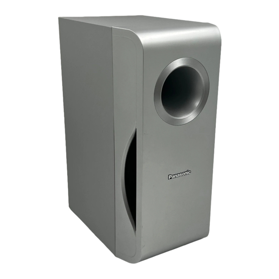
- Page 1 ORDER NO. MD0512499C7 Subwoofer System SB-W740P Colour (S)... Silver Type SPECIFICATIONS...
- Page 2 Specification Type 1 way, 1 speaker system (Bass-ref.) Speaker unit Impedance 4 Woofer 16 cm (6- 1 /2”) Cone type Input power (IEC) 320 W* (Max) Output sound pressure 80 dB/W (1.0 m) level Frequency range 32 Hz - 220 Hz (-16 dB) 38 Hz - 180 Hz (-10 dB) Dimensions (W x H x D) 183 mm x 396 mm x 267 mm...
-
Page 3: Assembling And Disassembling
2005 Matsushita Electric Industrial Co. Ltd.. All rights reserved. Unauthorized copying and distribution is a violation of law. 1. Assembling and Disassembling “ATTENTION SERVICER” Some chassis components may have sharp edges. Be careful when disassembling and servicing. 1. This section describes procedures for checking the operation of the major printed circuit boards and replacing the main components. - Page 4 Below is the list of disassembly sections - Disassembly of Front Cabinet Assembly - Disassembly of Woofer - Disassembly of Speaker Cabinet Assembly 1.1. Disassembly flow chart The following chart is the procedure for disassembling the casing and inside parts for internal inspection when carrying out the servicing.
- Page 5 Step 1: Upset the unit as shown above. Step 2: Insert a steel rule into the grooves of the Speaker unit. Push the steel rule forward and backward as arrow shown. Step 3: Insert a flathead screwdriver into the grooves as arrow shown. Ensure that the screwdriver is above the Steel rule.
- Page 6 and insert the Wood chip. Step 5: At the boss area push up as arrow shown to open the boss. Caution: Do not exert strong force as it may damage the Front Cabinet Assembly. 1.3. Disassembly of Woofer Follow (step 1) to (step 5) of item 1.2. Step 1: Remove all 4 screws from the Woofer.
- Page 7 Step 2: Insert a steel rule between the Woofer and Speaker Cabinet Assembly to push out the Woofer. Step 3: Take out the Woofer unit.
-
Page 8: Connection Of The Speaker Cables
Step 4: Remove the Woofer by detaching the (+) white and (-) blue wires. 1.4. Assembly of Subwoofer Unit Step 1: Scrape off using the scriber and clean up the remaining glue at the 6 bosses and 6 holes as arrow shown and replace with the normal glue. Step 2: Fix the Front Cabinet Assembly firmly back to the Speaker Cabinet Assembly. - Page 9 power supply cord. - The load impedance of any speaker used with this unit must be 4 - Be sure to connect the cable from the right speaker to the right terminal and the cable from the left speaker to the left terminal. 1.
- Page 10 seating position. The angles in the diagram are approximate. Used only supplied speakers - Using other speakers can damage the unit, and sound quality will be negatively affected. - Set the speakers up on an even surface to prevent them from falling.
- Page 11 Place to the right or left of the television, on the floor or a sturdy shelf so that it will not cause vibration. Leave about 30 cm (11- ”) from the television. Caution - Do not stand on base. Be cautious when children are near. e.g.
-
Page 12: Exploded View
3. Connection of Wiring Diagram 4. Exploded view 4.1. Cabinet Parts Location... - Page 13 4.2. Packaging Note: The diagram below shows the packaging for SB-W740P-S.
-
Page 15: Replacement Parts List
5. Replacement Parts List Notes : - Important safety notice : When replacing any of these components, be sure to use only manufacturer’s specified parts shown in the parts list. - [M] markings in the Remarks columns indicates parts supplied by PAVCSG.