Panasonic CQ-C7353N Service Manual
Hide thumbs
Also See for CQ-C7353N:
- Operating instructions manual (68 pages) ,
- Service manual (45 pages)
Table of Contents
Advertisement
Quick Links
TABLE OF CONTENTS
1 Service Navigation ----------------------------------------------- 2
2 Specifications ----------------------------------------------------- 3
3 Features ------------------------------------------------------------- 4
4 Technical Descriptions ----------------------------------------- 5
5 Disassembly and Assembly Instructions ---------------10
6 Block Diagram----------------------------------------------------13
7 Wiring Connection Diagram ---------------------------------16
8 Schematic Diagram ---------------------------------------------17
9 Printed Circuit Board-------------------------------------------21
10 Exploded View and Replacement Parts List -----------26
11 Schematic Diagram for Printing with A4 Size----------37
All manuals and user guides at all-guides.com
PAGE
AUTOMOTIVE AFTERMARKET
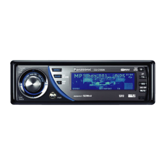
CQ-C7353N
WMA MP3 CD Player/Receiver
© 2007 Matsushita Electric Industrial Co., Ltd. All
rights reserved. Unauthorized copying and distribu-
tion is a violation of law.
ORDER NO. ACED070209C3
PAGE
Advertisement
Table of Contents

Related Manuals for Panasonic CQ-C7353N


Summary of Contents for Panasonic CQ-C7353N
-
Page 1: Table Of Contents
All manuals and user guides at all-guides.com ORDER NO. ACED070209C3 AUTOMOTIVE AFTERMARKET CQ-C7353N WMA MP3 CD Player/Receiver TABLE OF CONTENTS PAGE PAGE 1 Service Navigation ----------------------------------------------- 2 2 Specifications ----------------------------------------------------- 3 3 Features ------------------------------------------------------------- 4 4 Technical Descriptions ----------------------------------------- 5... -
Page 2: Service Navigation
All manuals and user guides at all-guides.com 1 Service Navigation 1.4. Maintenance Your product is designed and manufactured to ensure a mini- 1.1. About Lead Free Solder (PbF) mum of maintenance. Use a dry, a soft cloth for routine exterior cleaning. -
Page 3: Specifications
All manuals and user guides at all-guides.com 2 Specifications 2.2. Dimensions 2.1. Specifications* General Power Supply DC 12V (11V - 16V) Test Voltage 14.4V Negative Ground Tone Controls(Bass/Treble) Bass: ±12dB at 60 Hz Treble: ±12 dB at 16kHz Equalizer Center Frequency 60, 160, 400, 1 k, 3 k, 6 k, 16 kHz Variable Range of Equalizer -12 dB to 12 dB (2 dB step) -
Page 4: Features
CY-BT100N) • Expansion Module (The optional Hub unit: CY-EM100N) • The optional adapter allows you to connect the optional Panasonic DVD changer unit (CX-DH801N). • The optional adapter allows you to connect the optional Panasonic CD changer unit (CX-DP880). -
Page 5: Technical Descriptions
All manuals and user guides at all-guides.com 4 Technical Descriptions Port Description FM AM CD 45 CD SW1 Disc detection switch 1 4.1. Terminals Description 46 CD SW2 Disc detection switch 2 47 MOD0 Operating mode control 0 5.1 5.1 5.1 4.1.1. - Page 6 All manuals and user guides at all-guides.com Port Description Port Part Name & Description FM AM CD ROTARY 2 Volume-down detection from 99 ANT CONT Power control for antenna O 5.2 5.2 5.2 Rotary encoder motor Not connected 100 EP CS(NC) Not connected Not connected Not connected...
- Page 7 All manuals and user guides at all-guides.com Port Descriptions Not Connected SBSY DSP IC SBSY Not Connected Not Connected TXD0 Serial data output RXD0 Serial data input CLK0 Clock input TXD1 Serial data output RXD1 Serial data input CLK1 Clock input DVCC Power supply (3.3V) Crystal oscillator...
- Page 8 All manuals and user guides at all-guides.com 4.2. IC Block Diagram 4.2.1. Main Block IC670 : YEAMC14584BE IC730 : C0DAEKG00002 IC201 : C1BB00000796 IC701 : C0DAZHF00004 IC231 : C0JBZS000003 IC755 : C0DBZGD00040...
- Page 9 All manuals and user guides at all-guides.com IC760 : C0GBG0000032 4.3. Display Block IC902 : C0EBF0000374 4.4. CD Servo Block IC401, IC403 : YESAM341 IC402 : YESAM342...
-
Page 10: Disassembly And Assembly Instructions
All manuals and user guides at all-guides.com 5 Disassembly and Assembly Instructions 5.1. How to Remove the Flexible PCB(AP2) How to remove the flexible PCB(AP2) 1. Remove the trim plate. 5. Remove the flexible PCB(AP2) from the CN601 (E-3108a). CN601 Trim plate 2. - Page 11 All manuals and user guides at all-guides.com 5.2. How to Install the Main P.C.B of the Electric Display...
- Page 12 All manuals and user guides at all-guides.com...
-
Page 13: Block Diagram
AMP MUTE CD SCK Q372 STBY CD SI IC701 IC650 POWER SUPPLY CD SO LEVEL BATT ANT+B SHIFT Q652 CD SW1 SW5V Q651 AUDIO9V CD SW2 VDD5V ANT CONT MAIN CONT CD8V DECK V CONT ILM10V Q701 BATT CQ-C7353N MAIN-1... - Page 14 32.768KHz KS1-3 KEY-IN R-CH PANEL OPEN 30,37,38 MATRIX SW601 RESET BATT ILM10V PANEL CLOSE KI2-5 SW602 41–44 Q760 IC760 VOLT V CONT1 TH DETECT CONT 17 16 VDD3.3V CN760 OUT1 FP MOTOR1 MOTOR DRIVE OUT2 FP MOTOR2 CQ-C7353N MAIN-2/ DISPLAY...
- Page 15 X201 X101 TRACKING 21 X1 TRACKING COIL COIL DRIVE MUTE IC401 1.5V CD3.3V VCOM SPINDLE MOTER SPINDLE DRIVE MOTOR IC403 DSP1.5V CD3.3V DSP3.3V CD8V RESET IC402 SLED MOTER SLED LD EJ DRIVE MOTOR LD MT MUTE CQ-C7353N CD Deck Block...
-
Page 16: Wiring Connection Diagram
All manuals and user guides at all-guides.com 7 Wiring Connection Diagram External Mute CN351 <AUX1-IN> External Remote Control Amp-Relay Control Power CN255 <S.W. OUT> BATT CN202 <PRE-OUT REAR> CN302 Motor ANT <PRE-OUT FRONT> Not Used ACC GND Motor Speaker BATT FR+ FR- Power Connector... -
Page 17: Schematic Diagram
All manuals and user guides at all-guides.com 8 Schematic Diagram 8.1. Main-1 Block... - Page 18 All manuals and user guides at all-guides.com 8.2. Main-2 Block...
- Page 19 All manuals and user guides at all-guides.com 8.3. Display Block...
- Page 20 CD Servo Block 3032-14-35 0.5V/DIV,0.1µs/DIV 3.3V 3.3V YESAM343 2V/DIV,1ms/DIV 2V/DIV,5ms/DIV YESAN086 YESAM337 2V/DIV,5ms/DIV 3.3V YESAN116 B1GDCFJJ008 YESAM342 YESAN116 3.3V 3.3V MAIN CN651 3.3V 3.3V YESAM341 YESAM339 YESAM341 The following symbols are shown on the schematic diagram. 3.3V 3.3V CD(L,R) CQ-C7353N CD DECK...
-
Page 21: Printed Circuit Board
All manuals and user guides at all-guides.com 9 Printed Circuit Board 9.1. Main Block (Top View) - Page 22 All manuals and user guides at all-guides.com 9.2. Main Block (Bottom View)
- Page 23 All manuals and user guides at all-guides.com 9.3. Display Block...
- Page 24 All manuals and user guides at all-guides.com 9.4. CD Interface Block (Top View)
- Page 25 All manuals and user guides at all-guides.com 9.5. CD Interface Block (Bottom View)
-
Page 26: Exploded View And Replacement Parts List
CP904 CN902 CP905 CN901 LED P.C.B E-9782b LCD901 CD Deck Ass'y CN255 CN351 CN302 CN202 IC271 IC701 CN701 CN680 IC730 PA51 (CN255) (CN351) (CN302) Main P.C.B (CN202) ANT51 E-3108a CN760 SW602 CN651 CN670 <Installation Parts CN601 SW601 Trim Plate> CQ-C7353N... - Page 27 All manuals and user guides at all-guides.com 10.2. Replacement Parts List Notes : Ref. No. Part No. Part Name & Description Remarks DIODEs 1. Be sure to make your orders of replacement parts accord- D201 B0JCME000012 Diode ing to this list. D202 B0JCME000012 Diode...
- Page 28 All manuals and user guides at all-guides.com Ref. No. Part No. Part Name & Description Remarks Ref. No. Part No. Part Name & Description Remarks C317 YECUS1C334KX Ceramic, 0.33µF 16WV C632 YECUS1E104ZF Ceramic, 0.1µF 25WV C320 F1J1C225A138 Ceramic, 2.2µF 16WV C633 F2A1C470A630 Electrolytic, 47µF 16WV...
- Page 29 All manuals and user guides at all-guides.com Ref. No. Part No. Part Name & Description Remarks Ref. No. Part No. Part Name & Description Remarks J524 ERJ8GX0R00V Chip, 0Ω 1/8W R302 ERJ3GEYJ152V Chip, 1.5kΩ 1/16W J525 ERJ8GX0R00V Chip, 0Ω 1/8W R303 ERJ3GEYJ103V Chip, 10kΩ...
- Page 30 All manuals and user guides at all-guides.com Ref. No. Part No. Part Name & Description Remarks Ref. No. Part No. Part Name & Description Remarks R607 ERJ3GEYJ333V Chip, 33kΩ 1/16W R761 ERDS1FJ3R9 Carbon, 3.9Ω 1/2W R608 ERJ3GEYJ822V Chip, 8.2kΩ 1/16W R770 ERJ6GEY0R00V Chip, 0Ω...
- Page 31 All manuals and user guides at all-guides.com Ref. No. Part No. Part Name & Description Remarks Ref. No. Part No. Part Name & Description Remarks DIODEs R932 ERJ3GEYJ101V Chip, 100Ω 1/16W D901 B0BC5R600003 Diode R933 ERJ6GEYJ751V Chip, 750Ω 1/10W D903 B0BC4R000006 Diode R934...
- Page 32 All manuals and user guides at all-guides.com Ref. No. Part No. Part Name & Description Remarks Ref. No. Part No. Part Name & Description Remarks INSTALLATION PARTS XSB3+6FJ Binding Screw EUR7641010 Remote Control Unit (includes a bat- XSB26+5FJ Binding Screw tery) XTB3+6FFJ Tapping Screw...
- Page 33 All manuals and user guides at all-guides.com 10.3. Exploded View (CD Deck) CD Servo P.C.B [3032 14 35] GFX9995891...
- Page 34 All manuals and user guides at all-guides.com 10.4. CD Player Parts List Part No. Part Name & Description Remarks Ref.No. C227 YESCC439 Ceramic, 0.1µF 25WV Notes : C228 YESCC439 Ceramic, 0.1µF 25WV 1. Be sure to make your orders of replacement parts accord- C229 YESCC439 Ceramic, 0.1µF 25WV...
- Page 35 All manuals and user guides at all-guides.com Part No. Part Name & Description Remarks Part No. Part Name & Description Remarks Ref.No. Ref.No. R142 ERJ3GEY0R00V Chip, 0Ω 1/16W MECAHNICAL PARTS R201 YESRG224 Chip, 100kΩ 1/10W MISCELLANEOUS R202 YESRG355 Chip, 1MΩ 1/10W YESFX046136 Frame R203...
- Page 36 All manuals and user guides at all-guides.com Part No. Part Name & Description Remarks Ref.No. YESJS01148 Screw, 2*4 YERJW01001 P Washer, 3.5*8*0.3 YERJW01002 HL Washer, 1.85*5*0.13 YERJW01003 Lumilar Washer, 3.1*6*0.1 YEJE01028 E-Ring S 1.5 YERJW01005 P Washer, 2.1*4*0.13...
-
Page 37: Schematic Diagram For Printing With A4 Size
All manuals and user guides at all-guides.com 11 Schematic Diagram for Printing with A4 Size 11.1. Main-1 Block (Left Side) - Page 38 All manuals and user guides at all-guides.com 11.2. Main-1 Block (Right Side)
- Page 39 All manuals and user guides at all-guides.com 11.3. Main-2 Block (Left Side)
- Page 40 All manuals and user guides at all-guides.com 11.4. Main-2 Block (Right Side)
- Page 41 All manuals and user guides at all-guides.com 11.5. Display Block (Left Side)
- Page 42 All manuals and user guides at all-guides.com 11.6. Display Block (Right Side)
- Page 43 All manuals and user guides at all-guides.com 11.7. CD Servo Block (Left Side) 3032-14-35 YESAM343 YESAN086 B1GDCFJJ008 YESAN116 YESAM339 The following symbols are shown on the schematic diagram. 3.3V 3.3V CD(L,R)
- Page 44 All manuals and user guides at all-guides.com 11.8. CD Servo Block (Right Side) 3032-14-35 0.5V/DIV,0.1µs/DIV 3.3V 3.3V 2V/DIV,1ms/DIV 2V/DIV,5ms/DIV YESAM337 2V/DIV,5ms/DIV 3.3V YESAN116 B1GDCFJJ008 YESAM342 YESAN116 3.3V 3.3V MAIN CN651 3.3V 3.3V YESAM341 YESAM341 CQ-C7353N CD DECK...
- Page 45 All manuals and user guides at all-guides.com Printed in Japan 2007.2 (K) (Recycled Paper)