
Related Manuals for Huawei U9200


Summary of Contents for Huawei U9200
- Page 1 U9200 Maintenance Manual V1.0 Prepared by Date 2012-03-08 Reviewed by Date Approved by Date Huawei Technologies Co., Ltd. All rights reserved.
- Page 2 U9200 Maintenance Manual INTERNAL Change History Date Version Change Reason Section No. Description Author 2012-03-08 V1.0 Li Xianxi (2012-06-13) Huawei Proprietary and Confidential Page 2 of 80 Copyright © Huawei Technologies Co., Ltd.
-
Page 3: Table Of Contents
8.5 Gluing TP Components ..........................32 8.6 Pre-Pressing TP Components ......................... 32 8.7 Packing TP Components ..........................33 8.8 Installing the REC-FPC to the Main Board ....................33 (2012-06-13) Huawei Proprietary and Confidential Page 3 of 80 Copyright © Huawei Technologies Co., Ltd. - Page 4 9.19 MHL Failure ..............................68 9.20 WCDMA RF Receiving Failure ........................69 9.21 WCDMA RF Transmitting Failure ....................... 71 9.22 GSM RF Receiving Failure .......................... 73 (2012-06-13) Huawei Proprietary and Confidential Page 4 of 80 Copyright © Huawei Technologies Co., Ltd.
- Page 5 10 Functional Test .......................... 77 10.1 Keypad Introduction ............................. 77 10.2 MMI Test ..............................77 10.3 Wi-Fi Test ..............................80 10.4 Voice Call Test .............................. 80 (2012-06-13) Huawei Proprietary and Confidential Page 5 of 80 Copyright © Huawei Technologies Co., Ltd.
-
Page 6: Product Introduction
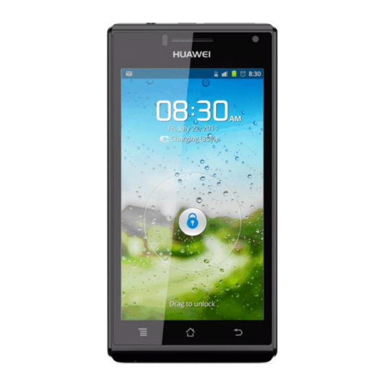
INTERNAL 1 Product Introduction 1.1 Appearance Figure 1-1 shows the U9200. Figure 1-1 U9200 1.2 Features Table 1-1 lists the specifications of the U9200. Table 1-1 Specifications of the U9200 Item Specifications Phone type Touchscreen smartphone Dimensions (H x W x D) 7.69 mm x 129 mm x 64.8 mm... - Page 7 Rear camera: 8 megapixels, autofocus, with dual LED flashlights Front camera: 1.3 megapixels Gravity sensor, proximity sensor, light sensor, and gyroscope Bluetooth, FM, GPS/AGPS WCDMA 3G/WLAN Huawei's Android app-store, Hi-Space (2012-06-13) Huawei Proprietary and Confidential Page 7 of 80 Copyright © Huawei Technologies Co., Ltd.
-
Page 8: Applicable Scope And Precautions
2.1 Applicable Scope This document provides repair instructions for technicians at service centers authorized by Huawei. This maintenance manual is confidential and accessible to authorized service centers (ASCs) and authorized service providers (ASPs) only. While every effort has been made to ensure the accuracy of this document, errors may still exist. -
Page 9: Exploded View
U9200 Maintenance Manual INTERNAL 3 Exploded View 3.1 Exploded View Figure 3-1 shows the exploded view of the U9200. Figure 3-1 Exploded view of the U9200 Battery Battery cover Bluetooth Shielding cover protective film antenna antenna cover Touchscreen- Receiver related... - Page 10 NOTE The list of components is provided for reference only. This list is subject to change without notice. The latest component list is available on Huawei's ITEM information system. If you have any questions, contact your local technical support center.
-
Page 11: Layout Of Components On Main Board
U9200 Maintenance Manual INTERNAL 4 Layout of Components on the Main Board Figure 4-1 shows the U9200's main board components. Figure 4-1 U9200's PCBA components U2003, gyroscope chip J1402, FPC connector J1500, headset jack J1801, front camera U1897, U1898, U1899,... - Page 12 U9200 Maintenance Manual INTERNAL Table 4-1 U9200's main board components Part Number Name Position 19040121 Protection Tube, Fast Blowout Fuse, 24 V, 2 A, IEC F1900 Spec, 0.03ohm, 0.100 A*A*Sec, UL, Terminal Dedicated IO Connector, Female, 5pin, WTB Connector, SMT,...
- Page 13 U1901 separate Power Path Control, WCSP, SMT, Terminal Dedicated 38140020 Semiconductor Sensor, three-axis gyroscope, SMT U2003 38140064 Semiconductor Sensor, Accelerometer, LGA, 3axis, U2004 Terminal Dedicated (2012-06-13) Huawei Proprietary and Confidential Page 13 of 80 Copyright © Huawei Technologies Co., Ltd.
- Page 14 PG-WFWLB-138-2 47140093 RF Switch, 824–2170MHz, SP8T ASM, 1.2dB max., U4703 1.6max.,LGA, Terminal Dedicated Temperature Compensated Oscillator, 26MHz, 12070027 U4708 +/-2.5ppm,1.8v-2.9v, +/-2.5ppm, 30degC, 85degC, Terminal Dedicated (2012-06-13) Huawei Proprietary and Confidential Page 14 of 80 Copyright © Huawei Technologies Co., Ltd.
- Page 15 NOTE The list of components is provided for reference only. This list is subject to change without notice. The latest component list is available on Huawei's ITEM information system. If you have any questions, contact your local technical support center.
-
Page 16: Software Upgrade
Create a folder named dload in the root directory of the microSD card. Copy the upgrade file update.app to the dload folder. Install the microSD card on the phone. (2012-06-13) Huawei Proprietary and Confidential Page 16 of 80 Copyright © Huawei Technologies Co., Ltd. -
Page 17: Troubleshooting
2. Check whether the upgrade file storage directory is correct. 3. Check whether the upgrade method is correct. 4. Check whether the microSD card functions properly. 5. Perform the upgrade again. (2012-06-13) Huawei Proprietary and Confidential Page 17 of 80 Copyright © Huawei Technologies Co., Ltd. -
Page 18: Maintenance Tools
Usage: to secure the PCBA Name: lead-free solder wire Usage: soldering Name: digital multimeter Usage: to measure during repair Name: toolkit Usage: to assemble and disassemble terminal products (2012-06-13) Huawei Proprietary and Confidential Page 18 of 80 Copyright © Huawei Technologies Co., Ltd. - Page 19 U9200 Maintenance Manual INTERNAL Name: electric screwdriver Usage: to fasten and remove screws (2012-06-13) Huawei Proprietary and Confidential Page 19 of 80 Copyright © Huawei Technologies Co., Ltd.
-
Page 20: Disassembly Procedure
(1) Stick a crowbar into the gaps at the bottom corners respectively, and pry outwards to remove the two buckles. (2) Remove the three bottom female buckles. (3) Remove the top three buckles. (2012-06-13) Huawei Proprietary and Confidential Page 20 of 80 Copyright © Huawei Technologies Co., Ltd. - Page 21 Figure 7-3 Reinstalling the volume keys Higher flexibility Lower flexibility (2012-06-13) Huawei Proprietary and Confidential Page 21 of 80 Copyright © Huawei Technologies Co., Ltd.
- Page 22 Disconnect the BTB connector. Figure 7-5 Removing the sub board Coaxial-line switch BTB connector Remove the main shielding cover and Flash_FPC. (1) Remove the four screws. (2012-06-13) Huawei Proprietary and Confidential Page 22 of 80 Copyright © Huawei Technologies Co., Ltd.
- Page 23 Take care not to damage the connector under the shielding cover or deform the shielding cover. Remove the shielding cover from the two buckles. (4) Disconnect the BTB connector from the Flash_FPC using tweezers, and remove the FPC. (2012-06-13) Huawei Proprietary and Confidential Page 23 of 80 Copyright © Huawei Technologies Co., Ltd.
- Page 24 Put your nail in the groove and move upwards to open the Coaxial-line switch battery connector. Stick tweezers into the bottom right corner of the main board. (2012-06-13) Huawei Proprietary and Confidential Page 24 of 80 Copyright © Huawei Technologies Co., Ltd.
- Page 25 (1) Remove the Bluetooth and GPS antennas. NOTE There is a buckle on the back of each antenna. Take care not to break the buckle. (2012-06-13) Huawei Proprietary and Confidential Page 25 of 80 Copyright © Huawei Technologies Co., Ltd.
- Page 26 Buckle Buckle (2) Remove the rear camera. Open the BTB connector, and remove the camera from the front surface. Figure 7-12 Removing the rear camera (2012-06-13) Huawei Proprietary and Confidential Page 26 of 80 Copyright © Huawei Technologies Co., Ltd.
- Page 27 Figure 7-13 Removing the front camera Silica gel jacket of the triple color LED The touchscreen and LCD are glued to the front cover, and cannot be disassembled. (2012-06-13) Huawei Proprietary and Confidential Page 27 of 80 Copyright © Huawei Technologies Co., Ltd.
-
Page 28: Assembly Procedure
8.2 Installing the Sub Board to the Front Cover Step 1 Paste a piece of adhesive on the back of the sub board, and tear off the liner. (2012-06-13) Huawei Proprietary and Confidential Page 28 of 80 Copyright © Huawei Technologies Co., Ltd. - Page 29 Step 2 Place one end of the sub board under the hook. Step 3 Install the sub board to the correct position where both ends are hooked tightly. (2012-06-13) Huawei Proprietary and Confidential Page 29 of 80 Copyright © Huawei Technologies Co., Ltd.
-
Page 30: Installing The Touch Key Fpc To The
FPC and the Step 5 Align the FPC with the two front cover. positioning pins, and paste it to the board. (2012-06-13) Huawei Proprietary and Confidential Page 30 of 80 Copyright © Huawei Technologies Co., Ltd. -
Page 31: Wiping The
8.4 Wiping the Front Cover Step 1 Wipe the areas to be glued using a piece of dust-free cloth with some absolute alcohol. Step 2 Tear off the liner. (2012-06-13) Huawei Proprietary and Confidential Page 31 of 80 Copyright © Huawei Technologies Co., Ltd. -
Page 32: Gluing Tp Components
8.6 Pre-Pressing Touchscreen Components Step 1 Place the front cover components Step 2 Power on the pre-pressing on the pre-pressing machine. machine, and press the components. (2012-06-13) Huawei Proprietary and Confidential Page 32 of 80 Copyright © Huawei Technologies Co., Ltd. -
Page 33: Packing Tp Components
Step 3 Paste the REC-FPC to the correct Step 4 Connect the two connectors on the position by aligning it with the two REC-FPC and the main board. positioning pins. (2012-06-13) Huawei Proprietary and Confidential Page 33 of 80 Copyright © Huawei Technologies Co., Ltd. -
Page 34: Installing Bluetooth And Gps Supports
REC FPC seal ring. Step 7 Paste a aligning it with the two camera and the main board. waterproof strip. antenna supporting pins. (2012-06-13) Huawei Proprietary and Confidential Page 34 of 80 Copyright © Huawei Technologies Co., Ltd. -
Page 35: Installing The Receiver And Pasting A Protective Film
Step 3 Press the antenna support at your left hand side first, and then right hand side. Install the main board to the front cover. (2012-06-13) Huawei Proprietary and Confidential Page 35 of 80 Copyright © Huawei Technologies Co., Ltd. -
Page 36: Installing The Rear Camera To The
(2012-06-13) Huawei Proprietary and Confidential Page 36 of 80 Copyright © Huawei Technologies Co., Ltd. -
Page 37: Installing The Coaxial Line To The
Step 3 Install the SPK support into the Step 4 Run the electric screwdriver to screw the SPK front cover as shown in the figure above. support with two square head screws. (2012-06-13) Huawei Proprietary and Confidential Page 37 of 80 Copyright © Huawei Technologies Co., Ltd. -
Page 38: Installing And Pressing The Battery
Step 4 Tear off the liner, and install the Step 5 Run the electric screwdriver to screw FPC key to the correct position. the shielding cover with 3# and 4# screws. (2012-06-13) Huawei Proprietary and Confidential Page 38 of 80 Copyright © Huawei Technologies Co., Ltd. -
Page 39: Installing And Screwing The Rear Cover
Step 5 Paste anti-dismantle labels to rear camera. Paste lens on it, and screw the rear cover with square head press it for three seconds. the screws. screws. (2012-06-13) Huawei Proprietary and Confidential Page 39 of 80 Copyright © Huawei Technologies Co., Ltd. -
Page 40: Troubleshooting Common Problems
The U9200 is Huawei's first smartphone supporting the combination of application processor (AP) and cellular modem. The U9200, based on the TI OMAP4 platform, is a bar-type smartphone, with two ARM Cortex-A9 1.5 GB cores and two LPDDR2 ports, supporting dual channels to improve system performance. - Page 41 U9200 Maintenance Manual INTERNAL Figure 9-2 Block diagram of the U9200 The main board is divided according to logical function into the following four subsystems: baseband (including the AP and modem BB), RF, power supply, and user interface. Table 9-1 describes the modules and units subordinated to each subsystem and their functions.
- Page 42 Broadcom BCM4330 Wi-Fi and peripheral circuits. Crystal 26 M TCVCXO and Provides high precision 26 MHz oscillator and control circuit local clock. frequency synthesizer (2012-06-13) Huawei Proprietary and Confidential Page 42 of 80 Copyright © Huawei Technologies Co., Ltd.
- Page 43 External antenna, The U9200 provides a built-in internal interface, antenna supporting WCDMA at and antenna high and low frequency bands. The protection U9200 provides a main antenna and Wi-Fi/Bluetooth/GPS antennas. User UART The UART1 port is connected to interface connector...
- Page 44 RTC. (2012-06-13) Huawei Proprietary and Confidential Page 44 of 80 Copyright © Huawei Technologies Co., Ltd.
- Page 45 OTG function now. For details on the conceptual diagram and component layout for maintenance, see the following compressed files. HD1U9200MG.rar bottom.rar top.rar (2012-06-13) Huawei Proprietary and Confidential Page 45 of 80 Copyright © Huawei Technologies Co., Ltd.
-
Page 46: Power-On Failure
Large current is usually caused by short circuit. The current reaches 500 mA or above (the over-current protection value of a USB charger) when using DC power supply. For U9200, large current is usually caused by ground short circuit of VBAT and VPH_PWR. -
Page 47: Low Current (Dc Power Supply)
Low current is usually caused by short circuit on the PM chip or system startup failure, which is due to a faulty main chip or memory chip. The low current ranges from 20 mA to several hundred mA. (2012-06-13) Huawei Proprietary and Confidential Page 47 of 80 Copyright © Huawei Technologies Co., Ltd. - Page 48 If the fault still cannot be located after you perform the preceding operations, start the OmapFlash_mDDRtest provided by TI to check whether the DDR2 is normal. Ensure that the PC can identify the port before you use the tool, because the PC is connected to the U9200 through a USB cable.
-
Page 49: No Current (Dc Power Supply)
If the DDR2 is in good condition, resolder or replace the AP (U301). 9.2.3 No Current (DC Power Supply) No current is usually caused by power supply channel absence, poor soldering, or power key circuit faults. (2012-06-13) Huawei Proprietary and Confidential Page 49 of 80 Copyright © Huawei Technologies Co., Ltd. -
Page 50: Charging Failure
U901. 9.3 Charging Failure The BQ24161 chip is specifically used for charge control. If the U9200 can operate normally but being charged, check the BQ24161 chip, and replace it with the U1901. If the phone still fails to be charged, the circuit monitoring the battery charge level may fail. In this case, replace the U1301. - Page 51 U9200 Maintenance Manual INTERNAL Figure 9-6 Schematic diagram of the charging circuit Figure 9-7 Schematic diagram of the battery management module (2012-06-13) Huawei Proprietary and Confidential Page 51 of 80 Copyright © Huawei Technologies Co., Ltd.
-
Page 52: Display Failure
Reconnect them. AMOLED and the main board in good condition? Replace the Is the AMOLED in good J1602 or condition? peripheral components. Replace the LCD. (2012-06-13) Huawei Proprietary and Confidential Page 52 of 80 Copyright © Huawei Technologies Co., Ltd. -
Page 53: Vibration Failure
Are the motor channel Resolder or and PCB cabling in replace the good condition? component. Resolder or replace the U901. (2012-06-13) Huawei Proprietary and Confidential Page 53 of 80 Copyright © Huawei Technologies Co., Ltd. -
Page 54: Microsd Card Identification Failure
U901. Are the Resolder or SD_DETECT and replace the signal cables in good signaling channel condition? component. Resolder or replace the U301. (2012-06-13) Huawei Proprietary and Confidential Page 54 of 80 Copyright © Huawei Technologies Co., Ltd. -
Page 55: Usim Card Identification Failure
Replace the AMOLED and touchscreen module with new modules, and determine the fault is located on the touchscreen or the main board. (2012-06-13) Huawei Proprietary and Confidential Page 55 of 80 Copyright © Huawei Technologies Co., Ltd. -
Page 56: Tp Failure
U901. Resolder or Are the RST, INT, and I2C signaling replace the TP channels in good condition? signaling channel element. Resolder or replace the J1602. (2012-06-13) Huawei Proprietary and Confidential Page 56 of 80 Copyright © Huawei Technologies Co., Ltd. -
Page 57: Touch Key Failure
Resolder or Are the RST, INT, and I2C replace the touch signaling channels normal? key element. Resolder or replace the J2202. (2012-06-13) Huawei Proprietary and Confidential Page 57 of 80 Copyright © Huawei Technologies Co., Ltd. -
Page 58: Proximity Sensor And Auto Light Sensor Failure
If the acceleration sensor is faulty, the compass sensor does not function because the software of the compass sensor depends on the acceleration sensor. This is a basis for determining the acceleration sensor failure. (2012-06-13) Huawei Proprietary and Confidential Page 58 of 80 Copyright © Huawei Technologies Co., Ltd. -
Page 59: Compass Sensor Failure
Is the power power supply supply normal? loop. Is the fault rectified after you replace the acceleration sensor chip U2005? Resolder or replace the U301. (2012-06-13) Huawei Proprietary and Confidential Page 59 of 80 Copyright © Huawei Technologies Co., Ltd. -
Page 60: Camera Failure
Is the signal Rectify the faults circuit of the of the FPC cable speaker in good and the J2202. condition? Resolder or replace the U1201. (2012-06-13) Huawei Proprietary and Confidential Page 60 of 80 Copyright © Huawei Technologies Co., Ltd. -
Page 61: Mic Failure
Rectify the faults Is the signal circuit in of the MIC, good condition? keypad, FPC cable, signal circuits on the main board. Replace the U1201. (2012-06-13) Huawei Proprietary and Confidential Page 61 of 80 Copyright © Huawei Technologies Co., Ltd. -
Page 62: Receiver Failure
Replace the FPC. condition? Rectify the faults Is the signal circuit in of the signal good condition? circuits on the main board. Resolder or replace the U1201. (2012-06-13) Huawei Proprietary and Confidential Page 62 of 80 Copyright © Huawei Technologies Co., Ltd. -
Page 63: Headset Failure
Replace the the left and right sound channels in faulty good condition? elements. Rectify the Is the headset circuit shorted? shorted circuits. Replace the U1201. (2012-06-13) Huawei Proprietary and Confidential Page 63 of 80 Copyright © Huawei Technologies Co., Ltd. -
Page 64: No Transmission Through Headset
Is the AUD_HBIAS voltage Locate and normal? rectify the fault. Is the MIC circuit in Rectify the fault the headset shorted? of the signal circuit. Replace the U1201. (2012-06-13) Huawei Proprietary and Confidential Page 64 of 80 Copyright © Huawei Technologies Co., Ltd. -
Page 65: Wi-Fi/Bluetooth Failure
Is the Z3599 in good condition? the signal circuit. Rectify the fault of Is the fault rectified after you the signal circuit. replace the U3501? (2012-06-13) Huawei Proprietary and Confidential Page 65 of 80 Copyright © Huawei Technologies Co., Ltd. -
Page 66: Fm Failure
Is the signal input Patch solder or circuit poorly soldered replace the faulty or shorted? component. Is the fault rectified after you replace the U3401? Replace the U1201. (2012-06-13) Huawei Proprietary and Confidential Page 66 of 80 Copyright © Huawei Technologies Co., Ltd. -
Page 67: Gps Failure
Is the fault rectified after you replace the U3699? Is the fault rectified after you replace the U3601? Replace the U301. Figure 9-26 Schematic diagram of GPS circuit (2012-06-13) Huawei Proprietary and Confidential Page 67 of 80 Copyright © Huawei Technologies Co., Ltd. -
Page 68: Mhl Failure
U3103 and the elements of the peripheral circuit respectively. Is the fault rectified after you replace the U3101? Replace the U301. (2012-06-13) Huawei Proprietary and Confidential Page 68 of 80 Copyright © Huawei Technologies Co., Ltd. -
Page 69: Wcdma Rf Receiving Failure
Is the fault rectified after you replace the matching circuit considering the unfavorable frequency band? Is the fault rectified after you replace the U4701? Replace the U3801. (2012-06-13) Huawei Proprietary and Confidential Page 69 of 80 Copyright © Huawei Technologies Co., Ltd. - Page 70 INTERNAL NOTE If all the RF indexes are abnormal, check the power supply circuit, antenna feedpoint, antenna switch board, antenna cable, and RF test socket. (2012-06-13) Huawei Proprietary and Confidential Page 70 of 80 Copyright © Huawei Technologies Co., Ltd.
-
Page 71: Wcdma Rf Transmitting Failure
Is the fault rectified after you replace the U4701? Is the fault rectified after you replace the matching circuit considering the unfavorable frequency band? Replace the U3801. (2012-06-13) Huawei Proprietary and Confidential Page 71 of 80 Copyright © Huawei Technologies Co., Ltd. - Page 72 If all the RF indexes are abnormal, check the power supply circuit, DC/DC transformer supplying power to the PA, antenna switch chip, RF cable, and main chip. (2012-06-13) Huawei Proprietary and Confidential Page 72 of 80 Copyright © Huawei Technologies Co., Ltd.
-
Page 73: Gsm Rf Receiving Failure
Is the fault rectified after you replace the matching circuit considering the unfavorable frequency band? Is the fault rectified after you replace the U4701? Replace the U3801. (2012-06-13) Huawei Proprietary and Confidential Page 73 of 80 Copyright © Huawei Technologies Co., Ltd. - Page 74 INTERNAL NOTE If all the RF indexes are abnormal, check the power supply circuit, antenna feedpoint, antenna switch board, antenna cable, and RF test socket. (2012-06-13) Huawei Proprietary and Confidential Page 74 of 80 Copyright © Huawei Technologies Co., Ltd.
-
Page 75: Gsm Rf Transmitting Failure
Is the fault rectified after you replace the U4701? Is the fault rectified after you replace the matching circuit considering the unfavorable frequency band? Replace the U3801. (2012-06-13) Huawei Proprietary and Confidential Page 75 of 80 Copyright © Huawei Technologies Co., Ltd. - Page 76 INTERNAL NOTE If all the RF indexes are abnormal, check the power supply circuit, antenna feedpoint, antenna switch board, antenna cable, and RF test socket. (2012-06-13) Huawei Proprietary and Confidential Page 76 of 80 Copyright © Huawei Technologies Co., Ltd.
-
Page 77: Functional Test
Home key Back key Generally, a smartphone has only a few keys. The U9200 has six keys, including three Android system keys on the touchscreen, a power key, volume up key, and volume down key. The U9200 battery cannot be replaced; therefore, the power key is designed with a forcible power-off function. - Page 78 The speaker plays the ringtone. If a headset is inserted, the ringtone is played from the headset receiver. Receiver test The speaker plays the ringtone. The ringtone is played from the receiver. (2012-06-13) Huawei Proprietary and Confidential Page 78 of 80 Copyright © Huawei Technologies Co., Ltd.
- Page 79 LCD displays the error information. Press the volume down key to enter the next test. If the SIM card is detected, the system automatically proceeds to the next test. (2012-06-13) Huawei Proprietary and Confidential Page 79 of 80 Copyright © Huawei Technologies Co., Ltd.
-
Page 80: Huawei Proprietary And Confidential
If the test is successful, stop the voice call test. If the test fails, repair the phone again or send it to the advanced maintenance center. (2012-06-13) Huawei Proprietary and Confidential Page 80 of 80 Copyright © Huawei Technologies Co., Ltd.