Dell S3100 Series Installation Manual
Hide thumbs
Also See for S3100 Series:
- Getting started manual (46 pages) ,
- Getting started manual (27 pages)

Related Manuals for Dell S3100 Series


Summary of Contents for Dell S3100 Series
- Page 1 Dell Networking S3100 Series Installation Guide December 2021 December 2021 Rev. A02...
- Page 2 © 2016 Dell Inc. All rights reserved. This product is protected by U.S. and international copyright and intellectual property laws. Dell and the Dell logo are trademarks of Dell Inc. in the United States and/or other jurisdictions. All other marks and names mentioned herein may be...
-
Page 3: Table Of Contents
Orderable S3100 Series Components...........................26 Chapter 3: Site Location and Preparation..................27 Site Selection..................................27 Cabinet Placement................................27 Rack Mount..................................27 Chapter 4: Install a S3100 Series System..................28 Unpacking a S3100 Series Switch..........................28 Storing Components.................................29 Installing a Power Supply..............................29 Replacing a Power Supply............................30 Installing a Fan Tray................................30... - Page 4 Connecting the Stacking Ports (Optional)......................37 Powering Up..................................38 Accessing the Console..............................38 Chapter 5: S3100 Series Technical Specifications............... 39 IEEE Standards................................... 41 Agency Compliance................................41 USA Federal Communications Commission (FCC) Statement................41 European Union EMC Directive Conformance Statement..................42 India......................................
-
Page 5: Chapter 1: About This Guide
● The Dell Configuration Guide for the S3100 Series describes software configuration. ● The Dell Command Line Reference Guide for the S3100 Series provides command line interface (CLI) information. ● The Dell Networking S3100 Series Release Notes provide information about upgrading the S3100 series. -
Page 6: Chapter 2: S3100 Series Systems
Introduction The S3100 series is a low-cost wireless closet switch/router product for copper connections to 1G endpoints with Power over Ethernet plus (PoE+) capability on 1G access ports. The series includes capabilities for 1/10GE switching with 1G copper links for campus network endpoints and 10G ports for uplinks to core/aggregation switches. -
Page 7: Features
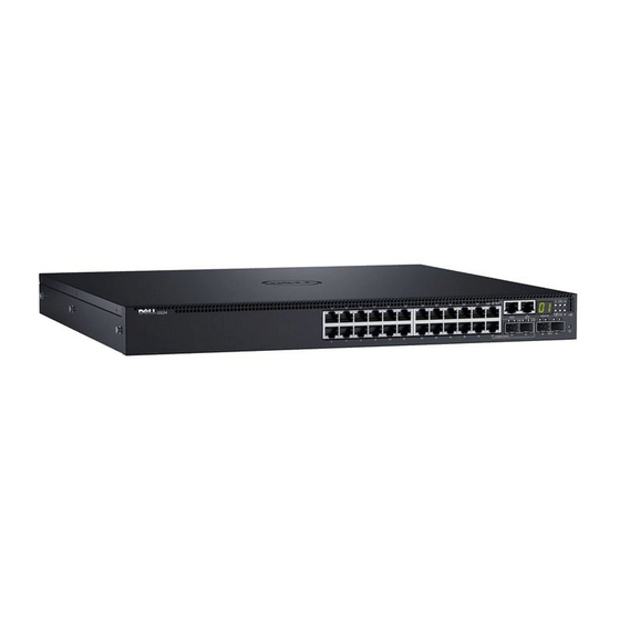
For details about PoE power consumption and budget, see S3100 Series Technical Specifications. For more information about all supported features and their implementation options, see the Dell Command Line Reference Guide for the S3100 Series and the Dell Configuration Guide for the S3100 Series. S3124 Platform I/O Side The S3124 platform input/output (I/O) side (shown in the following illustration) contains twenty-four 1G copper switch ports. -
Page 8: S3124 Platform Psu Side
5. PSU 2. NOTE: The S3124 platform does not support stacking with Dell Networking OS 9.8(2.0). S3124F Platform I/O Side The S3124F platform I/O side (shown in the following illustration) contains twenty-four 1G fiber switch ports. The I/O side also contains a console port, management port, serial bus port, reset button, two 10G SFP+ ports, and two 1G copper combo ports. -
Page 9: S3124F Platform Psu Side
5. PSU 2. NOTE: The S3124 platform does not support stacking with Dell Networking OS 9.8(2.0). S3148 Platform I/O Side The S3148 platform I/O side (shown in the following illustration) contains forty-eight 1G copper switch ports. The I/O side also contains a console port, management port, serial bus port, reset button, two 10G SFP+ ports, and two 1G SFP combo ports. -
Page 10: S3148 Platform Psu Side
1G SFP combo ports. Figure 8. S3124P I/O Side View 1. Console port. 2. Management port (RJ-45 type). 3. One universal serial bus port (USB Type-A) for storage. 4. Reset button. 5. Two 10G SFP+ ports. S3100 Series Systems... -
Page 11: S3124P Platform Psu Side
2. Management port (RJ-45 type). 3. One universal serial bus port (USB Type-A) for storage. 4. Reset button. 5. Two 10G SFP+ ports. 6. Two 1G SFP combo ports. 7. Forty-eight 1G copper switch ports including UPoE/PoE+ function. S3100 Series Systems... -
Page 12: S3148P Platform Psu Side
● One PSU — 715 Watt (default configuration) or 1100 Watt. ● Two PSUs — total of 1430 Watt or 2200 Watt. The S3148P platform includes the following PSU options: ● One PSU — 1100 Watt. ● Two PSUs — total of 2200 Watt. S3100 Series Systems... -
Page 13: Fans
Plug-in Modules One expansion slot is on the PSU side of the S3100 series chassis and can support either an SFP+ or 10GBase-T module. Each plug-in module has two ports. The modules are sold separately. Figure 12. SFP+ Module Figure 13. - Page 14 ● Solid green — link on 1 G speed. ● Solid amber — link on 100 M or 10 M speeds. ACT (Data transmission): ● Blinking green — activity. ● Off — no activity. Stack number ● Displays the stack unit number of the switch. S3100 Series Systems...
- Page 15 ● Solid amber — link on 100 Mbps speed. ACT (Data transmission): ● Off — no link. ● Blinking green — activity. The S3124F I/O side (shown in the following illustration) includes LED displays for port, system, and stack status. S3100 Series Systems...
- Page 16 LNK (Link speed): ● Off — no link. ● Solid green — link on 1 G speed. ● Solid amber — link on 100 M or 10 M speeds. ACT (Data transmission): ● Blinking green — activity. S3100 Series Systems...
- Page 17 ● Solid amber — link on 100 Mbps speed. ACT (Data transmission): ● Off — no link. ● Blinking green — activity. The S3148 I/O side (shown in the following illustration) includes LED displays for port, system, and stack status. S3100 Series Systems...
- Page 18 ● Solid amber — link on 100 M or 10 M speeds. ACT (Data transmission): ● Blinking green — activity. ● Off — no activity. Stack number ● Displays the stack unit number of the switch. ● Displays 1 if switch is not part of a stack. S3100 Series Systems...
- Page 19 ● Solid amber — link on 100 Mbps speed. ACT (Data transmission): ● Off — no link. ● Blinking green — activity. The S3124P I/O side (shown in the following illustration) includes LED displays for port, system, and stack status. S3100 Series Systems...
- Page 20 ● Solid green — link on 1 G speed. ● Solid amber — link on 100 M or 10 M speeds. ACT (Data transmission): ● Blinking green — activity. ● Off — no activity. Stack number ● Displays the stack unit number of the switch. S3100 Series Systems...
- Page 21 ● Solid amber — link on 100 Mbps speed. ACT (Data transmission): ● Off — no link. ● Blinking green — activity. The S3148P I/O side (shown in the following illustration) includes LED displays for port, system, and stack status. S3100 Series Systems...
- Page 22 ● Solid green — link on 1 G speed. ● Solid amber — link on 100 M or 10 M speeds. ACT (Data transmission): ● Blinking green — activity. ● Off — no activity. Stack number ● Displays the stack unit number of the switch. S3100 Series Systems...
- Page 23 ● Off — no link. ● Blinking green — activity. The SFP+ module (shown in the following illustration) includes LED displays for port status. Figure 19. SFP+ Module — PSU Side 1. SFP+ module port 1: LNK. S3100 Series Systems...
- Page 24 ● Solid green — link on 10 G speed. ● Solid amber — link on 100 M or 1 G speeds. Activity LED (right single color LED) ● Off — no link. ● Blinking green — activity. S3100 Series Systems...
- Page 25 ● Off — no link. ● Solid green — link. Activity LED (single color LED) ● Off — no link. ● Blinking green — activity. The power supply LED handle (item 1 in the following illustration) displays power supply status. S3100 Series Systems...
-
Page 26: Orderable S3100 Series Components
● Solid green — normal operation. ● Solid red — power failure. Orderable S3100 Series Components The S3100 series has the following orderable components: ● Second power supply (two is the maximum per switch). ○ S3124, , S3124F, and S3148 platforms support a 200W PSU. -
Page 27: Chapter 3: Site Location And Preparation
Site Location and Preparation You can mount S3100 series switches in a standard 48.26 cm (19-inch) rack or placed on a flat surface. You can install the system in: ● Network telecommunication facilities ● Data centers ● Other locations where the national electric code (NEC) applies NOTE: Install the system into a rack or cabinet before installing any optional components. -
Page 28: Chapter 4: Install A S3100 Series System
Install a S3100 Series System To install a S3100 series system, Dell Networking recommends completing the installation procedures in the order presented. Always handle the system and its components with care. Avoid dropping the system or its field replaceable units (FRUs). -
Page 29: Storing Components
5. If you have a redundant PSU (a second PSU), repeat steps 1 through 4 using the second PSU slot on the S3100 series system. -
Page 30: Replacing A Power Supply
Dell Networking Support. NOTE: If you use a single PSU, install a blank plate in the other PSU slot. Dell Networking recommends using power supply 1 (PSU1) as the blank plate slot. NOTE: The PSU slides into the slot smoothly. Do not force the PSU into a slot as this may damage the PSU or the chassis. -
Page 31: Replacing A Fan Tray
4. Tighten the captive screws on the replacement fan tray with a screwdriver. Ensure that the fan tray is secure. Installing a Plug-In Module (Optional) The S3100 series switches support SFP+ and 10GBase-T plug-in modules in the expansion slots on the PSU side of the switch. CAUTION: The plug-in modules are not hot-swappable. -
Page 32: Install Rack Or Cabinet Hardware
2. Align and seat the front flange pegs in the holes on the front side of the vertical post. See item 2 in the following illustration. 3. Repeat this procedure for the second rail. 4. To remove each rail, pull on the latch release button on each flange ear and unseat each rail. See item 3 in the following illustration. Install a S3100 Series System... -
Page 33: Configuring A Two-Post Flush-Mount
3. Slide the plunger bracket forward against the vertical post and secure the plunger bracket to the post flange with two user-supplied screws. See item 3 in the following illustration. 4. Repeat this procedure for the second rail. Figure 26. Installing the Switch using a Two-Post Flush-Mount Configuration Install a S3100 Series System... -
Page 34: Configuring A Two-Post Center-Mount
Torx driver. See item 1 in the following illustration. Retain the castings for future rack requirements. 2. For each rail, attach the front and rear flanges to the post flanges with two user-supplied screws at each end. See item 2 in the following illustration. Install a S3100 Series System... -
Page 35: Installing A 1U Two-Post
To install the switch in a 1U front-rack configuration, configure the rails that are attached to the system. 1. Attach the switch rails (inner chassis members) to the switch. Item 3 in the following illustration shows the detail for the front standoff with the locking tab. Install a S3100 Series System... - Page 36 About three inches before you fully insert your switch, the rail locking feature engages to keep the switch from inadvertently sliding out of the rack and falling. NOTE: Do not the use the mounted ReadyRails as a shelf or a workplace. Figure 30. Installing the Switch in a Front-Rack Configuration Install a S3100 Series System...
-
Page 37: Connecting The Stacking Ports (Optional)
You can (optionally) use the CLI to assign the master unit role, or select a different stack member as the standby unit, based on priority or MAC address. For more information, see the Dell Configuration Guide for the S3100 Series or the Dell Command Line Reference Guide for the S3100 Series. -
Page 38: Powering Up
2. Connect the other end of the cable to the DTE terminal server. 3. Set the default terminal settings as follows. ● 9600 baud rate. ● No parity. ● Eight data bits. ● One stop bit. ● No flow control. Install a S3100 Series System... -
Page 39: Chapter 5: S3100 Series Technical Specifications
Lithium Battery Caution: There is a danger of explosion if the battery is incorrectly replaced. Replace only with same or equivalent type. Dispose of the batteries according to the manufacturer's instructions. Table 10. S3100 Series Chassis Physical Design Parameter Specifications Height 1.71 inches (43.5 mm). - Page 40 The switch firmware controls the PoE power budget for each interface. The administrator can limit the power supplied on a port or prioritize power to some ports over others. For more information, see the Dell Command Line Reference Guide for the S3100 Series and the Dell Configuration Guide for the S3100 Series.
-
Page 41: Ieee Standards
Properly shielded and grounded cables and connectors must be used in order to meet FCC emission limits. Dell Networking is not responsible for any radio or television interference caused by using other than recommended cables and connectors or by unauthorized changes or modifications in the equipment. -
Page 42: European Union Emc Directive Conformance Statement
Equipment (VCCI). If this equipment is used in a domestic environment, radio disturbance may arise. When such trouble occurs, the user may be required to take corrective actions. NOTE: Use the AC power cords with Dell Networking equipment only. Do not use Dell Networking AC power cords with any unauthorized hardware. Figure 35. Japan: Warning Label... -
Page 43: Korean Certification Of Compliance
● IEC 60950-1, 2nd Ed, including all National Deviations and Group Differences Electromagnetic Compatibility (EMC) Emissions ● International: CISPR 22: 2008, Class A ● Australia/New Zealand: AS/NZS CISPR 22:2009, Class A ● Canada: ICES-003, Issue-4, Class A S3100 Series Technical Specifications... -
Page 44: Product Recycling And Disposal
EEE on the environment and human health due to the potential presence of hazardous substances in EEE. Dell Networking products, which fall within the scope of the WEEE, are labeled with the crossed-out wheelie-bin symbol, as shown above, as required by WEEE. -
Page 45: Chapter 6: Dell Networking Support
To participate in Dell community blogs and forums, go to https://www.dell.com/community. Topics: • Luggage Tag Luggage Tag The S3100 series systems have a pull-out tag (known as a luggage tag) on the PSU side of the system. 1. Service Tag 2. PPID 3. Express Service Code 4. MAC Address...