Table of Contents
Advertisement
Quick Links
SERVICE MANUAL
Ver 1.0 2000. 06
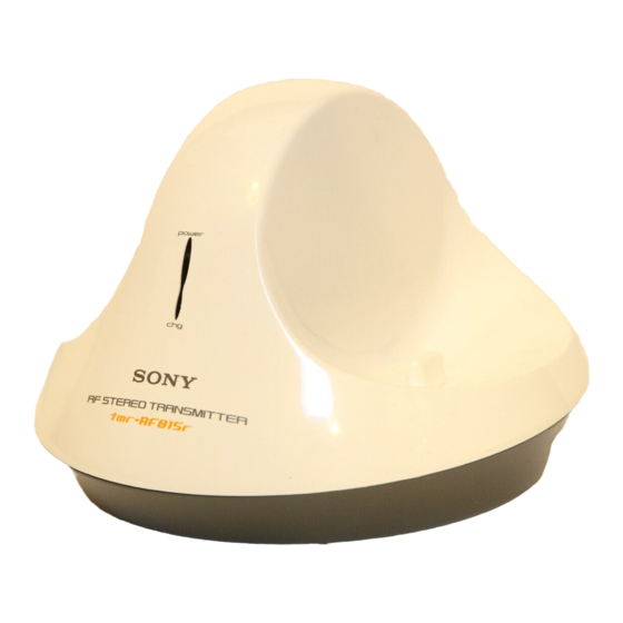
TMR-RF815R is the component model block one in the MDR-RF815RK.
COMPONENT MODEL NAME FOR MDR-RF815RK
Headphones
MDR-RF815R
Transmitter
TMR-RF815R
TMR-RF815R
SPECIFICATIONS
General
Carrier frequency
863.5 – 864.5 MHz
Channel
Ch1, Ch2, Ch3
Modulation
FM stereo
Frequency response
20 – 20,000 Hz
Transmitter
Power source
DC 9 V: supplied AC power
adaptor
Audio input
phono jacks/stereo mini jack
Approx. 150 mm dia × 108 mm
Dimensions
(6 × 4
1
/
in.) (w/h)
3
Mass
Approx. 190 g (6.2 oz.)
Design and specifications are subject to change without
notice.
AEP Model
UK Model
TRANSMITTER
Advertisement
Table of Contents

Related Manuals for Sony TMR-RF815R


Summary of Contents for Sony TMR-RF815R
- Page 1 TMR-RF815R SERVICE MANUAL AEP Model UK Model Ver 1.0 2000. 06 TMR-RF815R is the component model block one in the MDR-RF815RK. COMPONENT MODEL NAME FOR MDR-RF815RK Headphones MDR-RF815R Transmitter TMR-RF815R SPECIFICATIONS General Carrier frequency 863.5 – 864.5 MHz Channel Ch1, Ch2, Ch3...
-
Page 2: Section 1 General
SECTION 1 This section is extracted from instruction manual. GENERAL A To connect to a headphones jack Setting up the transmitter Transmitter to AUDIO IN A jacks Connect the transmitter to audio/video equipment. Select one of the hookups below depending on the jack type: DC IN 9V 1 2 3 OFF ON... -
Page 3: Section 2 Disassembly
SECTION 2 DISASSEMBLY Note : Follow the disassembly procedure in the numerical order given. 2-1. CABINET (UPPER) Cabinet (upper) × 8) 1 Four screws (P 2 2-2. TX-BASE BOARD 2 TX-BASE board Cabinet assy, lower — 3 —... -
Page 4: Section 3 Electrical Adjustments
3. Measure the movable terminal of RV403 using an digital volt- meter (AC range) and make sure the value is 1.6mVrms ± 0.1mV. If the measured value is other than the specified value, adjust to TMR-RF815R 1.6mVrms ± 0.1mV by turning the RV403 on the TX-BASE board. - Page 5 TMR-RF815R SECTION 4 DIAGRAMS 4-1. BLOCK DIAGRAM IC403 STEREO MPX ANT401 IC401 RV403 R-CH J401 INPUT BUFFER MOD IN TIME DEVISION AUDIO IN J402 R-CH IC405(2/2) POWER OFF NOISE T-OUT BUFFER CHARGE FILTER R-CH S401 NOISE FILTER D402 VCO UNIT...
- Page 6 TMR-RF815R 4-2. SCHEMATIC DIAGRAM 330p 100k — 7 — — 8 —...
- Page 7 TMR-RF815R 4-3. PRINTED WIRING BOARD • Semiconductor Location Ref. No. Location D401 D402 D403 D404 D405 D407 D408 D410 IC401 IC402 IC403 IC404 IC405 Q401 Q402 Q404 — 9 — — 10 —...
- Page 10 TX-BASE Ref. No. Part No. Description Remarks Ref. No. Part No. Description Remarks L409 1-419-079-21 COIL (MPX FILTER) R463 1-216-085-00 METAL CHIP 1/10W L410 1-419-662-31 COIL, AIR-CORE R464 1-216-061-00 METAL CHIP 3.3K 1/10W L413 1-414-234-11 INDUCTOR CHIP 0uH R466 1-216-081-00 METAL CHIP 1/10W L414 1-414-234-11 INDUCTOR CHIP 0uH...
- Page 11 TMR-RF815R Sony Corporation 2000F1646-1 Audio Entertainment Group 9-927-955-11 Printed in Japan © 2000.6 — 14 — Published by PE General Engineering Dept.