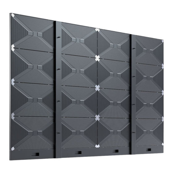
NEC LED-E012i-108 Installation And Maintenance Manual
Led display kit
Hide thumbs
Also See for LED-E012i-108:
- Installation and maintenance manual (53 pages) ,
- Installation and maintenance manual (94 pages)

Related Manuals for NEC LED-E012i-108


Summary of Contents for NEC LED-E012i-108
- Page 1 I n st a lla t ion a n d M a in t e n a n ce m a n u a l LED Display Kit [ Models for indoor use] LED-E012i-108 LED-E012i-217 LED-E015i-135 LED-E018i-162 LED-E025i-217 MODELS: LED-E012i, LED-E015i, LED-E018i, LED-E025i...
-
Page 2: Table Of Contents
Ta ble of Con t e n t s I m por t a n t I n for m a t ion ..............En glish - 1 Abou t t h e LED la m ps ..............En glish - 4 Lam p break- in ...................... -
Page 3: I M Por T A N T I N For M A T Ion
I m por t a n t I n for m a t ion Sa fe t y Pr e ca u t ion s a n d M a in t e n a n ce FOR OPTI MUM PERFORMANCE, PLEASE NOTE THE FOLLOWI NG WHEN SETTI NG UP AND USI NG THE LED DI SPLAY SYSTEM: Abou t t h e Sym bols... - Page 4 ● Be sure to read the following before using the product to use it correctly and safely. W ARN I N G Do not apply vibrat ions or shocks t o t he I nst all t he product so t hat t he vent s are not product .
- Page 5 CAUTI ON Do not dam age t he power cord. Do not put Do not use or st ore t he product in t he heavy obj ect s on it , place it near heat ers, pull following places. it wit h excessive st rengt h, or apply a st rong •...
-
Page 6: Abou T T H E Led La M Ps
Abou t t h e LED la m ps LED lam ps are sensit ive t o st at ic elect ricit y and surge volt age, which m ay dam age t heir com ponent s and decrease t heir reliabilit y. Take m easures against st at ic elect ricit y during t he inst allat ion. -
Page 7: Con T E N T S
The supplied part s are as follows. I n case one of t hese part s is m issing or dam aged, cont act t he ret ailer. Quant it y Specifications Part s LED-E012i-108 LED-E015i-135 LED-E018i-162 LED-E012i-217 LED-E025i-217 Bot t om fram e... - Page 8 Quant it y Specifications Part s LED-E012i-108 LED-E015i-135 LED-E018i-162 LED-E012i-217 LED-E025i-217 Cabinet alignm ent 35 x 35 x 6 m m bracket Fixing screw for t he Hexagonal socket cabinet alignm ent head screw ( M4 bracket x 12) Pixel card Cabinet 600 m m x 337.5...
-
Page 9: Pa R T S N A M E
Pa r t s N a m e 1 Pixel card 5 Power cord input / out put 2 Cabinet 6 Hub board 3 LAN cable input / out put 7 Power unit 4 LAN cable input ( not used wit h t his product ) English - 7... -
Page 10: I N St A Lla T Ion Ex A M Ple
I n st a lla t ion Ex a m ple 1 . I n st a lla t ion loca t ion Before t he inst allat ion, be sure t o review t he following safet y precaut ions t o ensure proper and safe inst allat ion. - Page 11 min. distance to floor m in. dist ance t o ceiling 500 m m 700 m m English - 9...
-
Page 12: I Nst Allat Ion Set Up
2 . I n st a lla t ion Se t u p 2.1 Mark t he posit ions of t he anchor point s on t he wall • Mark the positions of the holes you will make for the anchor points (refer to the figures below and the “Anchor point s num ber and posit ions”... - Page 13 1200 m m 1200 m m 1200 m m 337.5 m m 337.5 m m 337.5 m m 337.5 m m 337.5 m m 337.5 m m 337.5 m m Anchor point s posit ions: LED- E012i- 217, LED- E025i- 217 Anchor point s num ber and posit ions LED- E012i- 217, Fram e set...
- Page 14 2.3 I nst all t he m ount ing bars ( 1) I nst all t he m ount ing bars on t he anchor point s on t he wall. ( 2) Check t he dist ance bet ween t he m ount ing bars using t he alignm ent bars. 1800 m m Alignm ent bar 1200 m m...
- Page 15 1200 m m 1200 m m Alignm ent bar 1200 m m Alignm ent bar LED- E012i- 217, LED- E025i- 217 ( 3) Check t he evenness using a spirit level and t he alignm ent bars t oget her. Adj ust t he posit ions if required. M10 screws Wall m ount ed: Mount ing bar inst allat ion ( LED- E015i- 135) English - 13...
- Page 16 2.4 I nst all t he bot t om fram e Rem ove t he bot t om fram e cover and inst all t he bot t om fram e using M6 screws. H ow t o r e m ove t h e bot t om cove r ( 1) Rem ove t he screws securing t he bot t om fram e cover.
- Page 17 M6 screws Bot t om fram e When using t he 8 x 8 fram e set , use t he bot t om fram e connect ing part t o inst all t he bot t om fram e. Bot t om fram e connect ing screw ( PM3) ( 8 red circles) Bot t om fram e connect ing screw ( KM3)
- Page 18 2.6 I nst all t he cabinet s Hook t he hanger pins, which have been insert ed int o t he cabinet s, int o t he holes on t he m ount ing bars st art ing from t he lowest row. Fix temporarily the cabinets of the first row to the bottom frame.
- Page 19 Hook t he hanger pins of t he cabinet s of t he second row t o t he m ount ing bars. Secure t he LED cabinet s t oget her using connect ion screws for LED m odules. Do not t ight en t he screws com plet ely.
- Page 20 H ow t o con n e ct t h e pow e r cor d (1) Raise the lever. ( 2) I nsert t he wire. ( 3) Ret urn t he lever t o it s previous posit ion. Wire sizes com pat ible wit h t he power connect or ( WAGO) are as follows.
- Page 21 Insert the slot nuts inside the over frame into the holes of the connection screws for the LED modules and fix t hem wit h M3 screws. Slot nut s I nst all t he corner part s t o t he over fram e ( t op) and inst all it on t he t op of t he cabinet s. Slot n u t in st a lla t ion loca t ion s LED- E012i- 108 LED- E015i- 135...
- Page 22 2.7 Assem bly diagram s LED- E012i- 108 2412 1200 2400 Through hole for t he LAN cable LED- E015i- 135 3012 1800 3000 Through hole for t he LAN cable English - 20...
- Page 23 LED- E018i- 162 3612 1200 1200 3600 Through hole for t he LAN cable LED- E012i- 217, LED- E025i- 217 4812 1200 1200 1200 4800 Through hole for t he LAN cable English - 21...
-
Page 24: Wiring
3 . W ir in g LED- E012i- 108 by client Control PC by client LED Controller Main HDMI 1 by client LED- E015i- 135 by client Control PC by client LED Controller Main HDMI 1 by client LED- E018i- 162 by client Control PC LED Controller Main... - Page 25 LED- E012i- 217 by client by client LED Controller Main Control PC HDMI 1 by client LED- E025i- 217 by client Control PC LED Controller Main by client HDMI 1 by client English - 23...
- Page 26 ( 1) Power cord connect ion Connect the power cords to the LED modules on the first row. The power cord m ust be securely plugged. Connect t he power cords bet ween t he LED m odules. English - 24...
- Page 27 ( 2) LAN cable connect ion Connect t he LAN cables for t he signal bet ween t he LED m odules. Use t he t hrough holes t o pass t he cables bet ween t he m odules. Six t hrough holes for t he LAN cables LAN connect ors [ Con n e ct ion e x a m ple 1 ] Connect ing from bot t om t o t op using m ult iple port s...
- Page 28 [ Con n e ct ion e x a m ple 2 ] Connect ing all t he LED m odules using a single LAN cable LAN cable from t he LED cont roller Hub board Connect t he cable t o t he LAN connect or on t he left .
-
Page 29: I Nst Alling T He Pixel Card
4 . I n st a llin g t h e pix e l ca r d CAUTI ON • The pixel cards cont ain powerful m agnet s. I f m agnet ic cards com e close t o t he pixel cards, t he dat a cont ained wit hin m ay be dam aged. - Page 30 Magnet Magnet Guide pin Guide hole ( 3) Check t hat t he pixel card st ays securely in place and t hen t urn t he m aint enance t ool off. English - 28...
-
Page 31: Screen Configuration
Screen Configuration Check t hat all t he connect ions are com plet ed, and t hen t urn on t he LED m odules and t he LED cont roller. Power dist ribut or LED cont roller CONTROL INPUT OUTPUT Cont rol signal Video signal... - Page 32 Setting the screen configuration Perform t he set t ing using t he LCT- Mars cont rol soft ware by Novast ar. Log in wit h t he adm inist rat or privileges. Display t he login screen as follows: User( U) → Advanced Synchronous Syst em UserLogin( A) . Ent er t he password ( “...
- Page 33 Select “ St andard Screen” under “ Screen Type” ( d) . The set t ings in “ Sending Card Num ber ” ( e) and “ Et hernet Port No.” ( f ) vary depending on t he connect ed LED cont roller. ( d) ( h) ( e)
- Page 34 [Configuration example] The set t ing values are given for t he following exam ple where 16 LED- E012i m odules ( pixel pit ch of 1.25 m m ) are installed in a 4 (columns) x 4 (rows) configuration. CONTROL INPUT OUTPUT...
- Page 35 ( 2) Since the configuration is 4 (columns) x 4 (rows), enter Columns=4 and Rows=4. A 4 (columns) x 4 (rows) screen configuration is displayed. English - 33...
- Page 36 ( 3) I f m ult iple LED cont rollers are used, select t he num ber of t he connect ed LED cont rollers. Since only one cont roller is used in t his exam ple, it is not necessary t o set “ Sending Card Num ber” ( e) . ( 4) Configure the connection.
- Page 37 Follow t he sam e procedure for Port 3 and Port 4. English - 35...
- Page 38 ( 4) - 2 Connect ing all t he LED m odules using a single LAN cable The syst em is connect ed t o port 1 of t he LED cont roller. Select “ 1” ( port 1) under “ Et hernet Port No.” ( f ) . Click ( select ) t he connect ion pat t ern under “...
- Page 39 The select ion is done aut om at ically t o obt ain t he screen below. ( j ) ( k) ( l) ( 5) Save t he set t ings. ( a) Click the “Send to HW” button (j). When the dialog box indicating that the process finished successfully is displayed, click OK.
-
Page 40: I M A Ge Se T T In G
I m a ge Se t t in g You can adj ust t he bright ness, t he gam m a correct ion value, and t he color t em perat ure. Click “ Bright ness” on t he t op screen t o display t he following window. ( b) ( a) Click “Advanced Set t ings”... - Page 41 Click “Advanced Set t ings” ( ) ( a) t o expand t he set t ing screen. ( 1) Bright ness Set t he bright ness of t he screen using t he slider ( b) . I ncreasing t he value increases t he bright ness. ( 2) Gam m a correct ion Set t he gam m a correct ion value using t he slider ( c) .
-
Page 42: M A In T E N A N Ce
M a in t e n a n ce CAUTI ON • Disconnect t he power supply t o t he LED m odules when perform ing t he m aint enance. • Use t he correct screwdriver for t he shape of t he screws when rem oving ( loosening) or set t ing ( t ight ening) t he screws. - Page 43 Re m ovin g t h e pow e r su pply Disconnect t he LAN cable connect ed t o t he hub board. Rem ove t he 10 screws securing t he hub board, and t hen rem ove t he hub board. Then, rem ove t he t wo screws securing t he t erm inal cover.
- Page 44 Re m ovin g t h e r e ce ivin g ca r d Rem ove t he receiving card from t he hub board. Rem ove t he four screws securing t he receiving card, and t hen rem ove t he receiving card from t he hub board.
-
Page 45: Tr Ou Ble Sh Oot In G
Tr ou ble sh oot in g 1 . D ispla y pr oble m s Pr oble m Solu t ion Not hing is displayed on Check t hat power is being supplied t o t he LED m odules. all t he LED m odules. -
Page 46: St At E M Onit Oring Using T He Soft Ware
2 . St a t e m on it or in g u sin g t h e soft w a r e I n case of a problem , you will be able t o det erm ine t he locat ion where it occurred by m onit oring t he st at e of t he syst em . - Page 47 2 - 2 D ispla y u n de r a bn or m a l con dit ion s ( 1) Problem wit h t he input signal t o t he LED cont roller When t he display is red, t here is a problem wit h t he LED cont roller.
- Page 48 ( 2) Problem wit h t he LED m odules When t he display is red, t here is a problem wit h t he LED m odule operat ion. To display m ore det ails, click “ Monit oring”, and t hen click “ Receiving card” on t he screen t hat is displayed. I n t he exam ple shown on t he left , t he following problem s m ust be considered.
- Page 49 ( 3) Problem wit h t he int ernal t em perat ure of t he LED m odules There is a problem wit h t he LED m odule operat ion. To display m ore det ails, click “ Monit oring”, and t hen click “ Tem perat ure” on t he screen t hat is displayed. The LED m odules wit h a high t em perat ure are displayed in warm colors.
- Page 50 ( 4) Com m unicat ion problem When t he display is grey, t he com m unicat ion is not est ablished. → Check t hat t he USB cable is connect ed. → Check t hat t he LED cont roller is t urned on.
-
Page 51: Specifications
Specifications Models for indoor use LED- E012i- 108 LED- E015i- 135 LED- E018i- 162 LED- E025i- 217 LED- E012i- 217 Module LED- E012i LED- E015i LED- E018i LED- E025i LED- E012i LED configuration 3- in- 1 SMD Pixel pit ch 1.25 m m 1.56 m m 1.88 m m... -
Page 52: D Ia Gr A M
D ia gr a m LED - E0 1 2 i / LED - E0 1 5 i / LED - E0 1 8 i / LED - E0 2 5 i 43.0 32.0 4- M5 8- M5 16.0 ( Unit : m m ) English - 50... - Page 53 LED - E0 1 2 i / LED - E0 1 5 i / LED - E0 1 8 i / LED - E0 2 5 i Ca bin e t a lign m e n t br a ck e t 4-Φ5 ( Unit : m m ) English - 51...