Toshiba nv Series Instruction Manual
Ethernet (fn812) module
Hide thumbs
Also See for nv Series:
- Hardware manual (177 pages) ,
- Instruction manual (148 pages) ,
- User manual (70 pages)
Table of Contents
Advertisement
Quick Links
Advertisement
Table of Contents

Related Manuals for Toshiba nv Series


Summary of Contents for Toshiba nv Series
- Page 1 6F8C1361 Unified Controller nv Series Ethernet (FN812) Module Instruction Manual...
- Page 2 (4) All possible measures have been taken to prepare the information herein. If you have any question, comment, or find any error, please contact us. TC-net, PROSEC, TOSLINE, TOSDIC, CIEMAC are registered trademarks of Toshiba Infrastructure Systems & Solutions Corporation IBM is a registered trademark of International Business Machines Corporation.
- Page 3 Indicates Warning. Specific details are indicated near the symbol with pictures and text. Warning (Note) Descriptions of Prohibition, Mandatory Action, and Warning vary depending on the display on the main unit. Unified Controller nv series Ethernet (FN812) Module Operation Manual...
- Page 4 Safety Precautions on Installation WARNING Ground the device. Otherwise, it may cause an electric Ground shock or fire. CAUTION Do not install, store, or use it in Do not block the ventilation hole or the following environments. air inlet/outlet. Prohibited Prohibited ・...
- Page 5 Wipe off stain on the device, module, or board. module, or board with a soft cloth. Mandatory For severe stain, use a wet cloth wrung tightly. Leaving them stained may cause wrong decision or malfunction. Unified Controller nv series Ethernet (FN812) Module Operation Manual...
- Page 6 Upon faulty operation or failure, No touch energization. contact Toshiba's branch office or service offices. It may cause an electric shock. The power supply module is for the nv series only. Do not use it alone for any Before using, check that the power other purposes.
- Page 7 For transportation and storage of the product, use a conductive bag When destroying the product, observe Mandatory Prohibited and packaging box. the ordinances and rules of the local government. Otherwise it will cause failure. Unified Controller nv series Ethernet (FN812) Module Operation Manual...
- Page 8 (e.g. employing fool-proof design, fail-safe design, or redundant design). Disclaimer Toshiba shall not be responsible for any damage caused by fire or earthquake, acts of a third party, other accidents, the user's willful acts or negligence, misuse, or use in abnormal conditions.
- Page 9 • Unified Controller nv series/Integrated Controller V series Command Manual (6F8C1226) Describes the detailed specifications of the instruction words of the program languages (LD, FBD, and SFC) supported by the nv series and Integrated Controller V series. • Unified Controller nv series/Integrated Controller V series nV-Tool (Basic) Operation Manual (6F8C1290) Describes how to create, debug, print, and save programs using nV-Tool.
- Page 10 ●Notational conventions The following are the notational conventions for better understanding of this document. Describes what the user should be particularly aware of to handle the product correctly. Important: Describes what the user should observe to handle the product correctly. Note: Describes a remark.
-
Page 11: Table Of Contents
3.3.1 Network parameter setting ············································21 3.3.2 Multicast address setting ···············································30 Network Information ····················································· 32 3.4.1 LAN control information ···············································32 3.4.2 MIB information ····························································33 Chapter 4 Operation …35 Chapter 5 Troubleshooting …37 Unified Controller nv series Ethernet (FN812) Module Operation Manual... - Page 12 Inspection········································································ 41 Chapter 6 6.1.1 Daily inspection ····························································41 Maintenance and 6.1.2 Periodical inspection ····················································41 Inspection Life Limited Parts ·························································· 42 …39 Information by Socket ·················································· 45 Chapter 7 7.1.1 Configuration of information by single Ethernet socket ·····45 Application 7.1.2 Configuration of information by redundant Ethernet socket····46 Interface 7.1.3 Referring to information by socket·································47...
- Page 13 Appendix D Decimal-hexadecima l Conversion Table …61 Appendix E Sample Programs …65 Appendix F Return Code List …77 Unified Controller nv series Ethernet (FN812) Module Operation Manual...
- Page 14 Chapter 1 Introducing the FN812 Module This chapter describes the functions, characteristics, and names and functions of FN812 module. Functions and Characteristics of the FN812 Module ·····················································································2 Names and Functions of the Parts···························4 1.2.1 Names of the parts ···········································4 1.2.2 Functions of the parts·······································5...
-
Page 15: Functions And Characteristics Of The Fn812 Module
Functions and Characteristics of the FN812 Module The FN812 module is a device to connect the controller main unit of the Unified Controller nv series to the operator station OIS-DS of Toshiba CIE Integrated Control System CIEMAC-DS via the monitoring control network Ethernet. - Page 16 1.1 Functions and Characteristics of the FN812 Module Example of system configuration Host system network Monitoring control network 10M/100M/ 1Gbps Ethernet Unified Controller nv series TC-net I/O system Figure 1-1 System configuration example Unified Controller nv series Ethernet (FN812) Module Operation Manual...
-
Page 17: Names And Functions Of The Parts
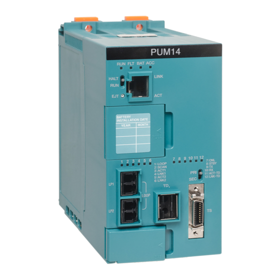
Chapter 1 Introducing the FN812 Module Names and Functions of the Parts 1.2.1 Names of the parts Figure 1-2 shows the names of the parts of the FN812 module. State display LED 状態表示LED • RUN ・RUN • ERR ・ERR • L-A ・L-A •... -
Page 18: Functions Of The Parts
2. If 1G-B and 100M-B are OFF, a link has been established at 10Mbps. 3. Check the LED states from the front. 4. Refer to “Table 5-1 Diagnosis using the LEDs.” Unified Controller nv series Ethernet (FN812) Module Operation Manual... - Page 19 Chapter 1 Introducing the FN812 Module Station address setting switch (STN-H, STN-L) Switches to set the station address in hexadecimal. For setting method, refer to "Chapter 3 Setting." Operation mode setting switch (MODE) Switches to set the operation mode. For setting method, refer to "Chapter 3 Setting."...
- Page 20 Chapter 2 Installation and Wiring This chapter describes installation and wiring methods of the FN812 module. Installation (Installation to the Basic Unit) ··············8 Connecting the Ethernet Cable ······························10 Connecting the Serial Communication Port (RS-232C) Cable ········································································11 Replacing the Module ············································12...
-
Page 21: Installation (Installation To The Basic Unit)
Chapter 2 Installation and Wiring Installation (Installation to the Basic Unit) Before installing or removing the module, make WARNING sure that the basic unit to which the FN812 Mandatory module is installed is turned off. Otherwise, it may cause an electric shock. Do not touch the interior of the product except WARNING the switches. - Page 22 After installing it to the basic unit, secure it using the screws at the top and bottom of the module. Basic unit FN812 module Module guide of basic unit Figure 2-1 Installing to the basic unit Unified Controller nv series Ethernet (FN812) Module Operation Manual...
-
Page 23: Connecting The Ethernet Cable
Mandatory When an error occurs such as unable to turn on the power, stop using and contact one of Toshiba's service representatives. If you have any question, consult with one of Toshiba's service representatives. 1000BASE-T/100BASE-TX/10BASE-T Connect the cable in the following steps. -
Page 24: Connecting The Serial Communication Port (Rs-232C)
(TOOL) can be used to communicate with the tool. RS-232C is used for communication. The RS-232C cable connector is a 9-pin D-sub connector (socket). FN812 module Serial communication port (TOOL) RS-232C cable Figure 2-3 Connecting the serial communication port Unified Controller nv series Ethernet (FN812) Module Operation Manual... -
Page 25: Replacing The Module
Chapter 2 Installation and Wiring Replacing the Module Turn off the basic unit. CAUTION When replacing the module, turn off the basic unit and Mandatory make sure that the power is off. Otherwise, failure of the module or electric shock may occur. When changing the switch settings or in case of failure, replace the module in the following steps. - Page 26 Hold the hook of the modular connector and remove the cable. Module guide of basic unit Figure 2-4 Replacing the FN812 module Unified Controller nv series Ethernet (FN812) Module Operation Manual...
- Page 27 Chapter 2 Installation and Wiring 6F8C1361...
- Page 28 Chapter 3 Setting Switch Setting ························································16 3.1.1 Station address setting switch (STN-H, STN-L) ···16 3.1.2 Operation mode setting switch (MODE) ········17 Network Parameter Setting·····································18 3.2.1 Station address ·············································18 3.2.2 Overview of multicast address ·······················18 Setting with the Engineering Tool ··························20 3.3.1 Network parameter setting ·····························21 3.3.2 Multicast address setting································30 Network Information ··············································32...
-
Page 29: Switch Setting
Chapter 3 Setting Switch Setting The switches that determine the operation mode and station address are on the front panel of the FN812 module. The method to set the switches is shown below. Important • Set the switches that determine the operation mode and station address of the FN812 module before turning the power on. -
Page 30: Operation Mode Setting Switch (Mode)
For maintenance Reserved Not used Reserved Not used Reserved Not used Reserved Not used Reserved Not used Operation mode Normally use the normal setting state. Important • Never use the maintenance mode. Unified Controller nv series Ethernet (FN812) Module Operation Manual... -
Page 31: Network Parameter Setting
Chapter 3 Setting Network Parameter Setting The network parameters can be set with the operation mode setting switches and station address setting switches. For methods to set these switches, refer to "Table 3-1 Station address setting" and "Table 3-2 Operation mode setting table." For the FN812 module, the following network parameters must be set. - Page 32 • Controllers 1, 2, 4 239.128.0.1 • Controllers 3, 6 239.128.0.2 • Controllers 5 239.128.0.1 and 239.128.0.2 The setting above allows messages to be passed to the controllers that belong to the group simultaneously. Unified Controller nv series Ethernet (FN812) Module Operation Manual...
-
Page 33: Setting With The Engineering Tool
Controller V series nV-Tool (Basic) operation manual" (6F8C1290). Connect the engineering tool and nv series controller via Ethernet. In the nv controller side, connect the RS-232C cable to the serial communication port (TOOL) on the front of the FN812 module (system configuration in Figure 3-2). -
Page 34: Network Parameter Setting
Figure 3-3 Station registration screen Set the station name. Select "nv station" from Station model name, and set the station name ("Stn1" is set in this example). Figure 3-4 Station name setting screen Unified Controller nv series Ethernet (FN812) Module Operation Manual... - Page 35 Chapter 3 Setting Add the unit to the station. Select [Unit] under the created station, and select [New (W)] from [File (F)] on the menu bar. Figure 3-5 Unit registration screen Add the module to the unit. Select [Module] under the unit, and select [New (W)]. Select "FN812 module"...
- Page 36 Select the added FN812 module. When [Module parameter] is selected from [File (F)] on the menu bar, the module parameter screen is displayed. Figure 3-7 An example of module registration screen Unified Controller nv series Ethernet (FN812) Module Operation Manual...
- Page 37 Chapter 3 Setting When the registration above is complete, check that the network information of the corresponding FN812 module can be read from the serial communication port (TOOL). From the product tree, open the module parameter screen for the FN812 module previously registered.
- Page 38 • If the controller is in a redundant configuration, the module parameters of the FN812 can be downloaded independently by selecting [Primary (P)] and [Secondary (S)] from [Transmission target]. Restart it. The downloaded information becomes effective at the next startup. After the download is complete, restart it. Unified Controller nv series Ethernet (FN812) Module Operation Manual...
- Page 39 Chapter 3 Setting From the product tree, set the network. Select the network under the system, and select [New (W)]. Figure 3-10 Network registration screen Select [EtherLANDouble] from the network addition dialog. Figure 3-11 Network addition dialog 6F8C1361...
- Page 40 Figure 3-12 Network module registration screen Connect to [EtherLANDouble]. The FN812 module previously added is displayed in the module addition dialog. Select it to connect to EtherLANDouble. Figure 3-13 Network module addition dialog Unified Controller nv series Ethernet (FN812) Module Operation Manual...
- Page 41 Chapter 3 Setting Figure 3-14 EtherLANDouble connection screen Connect the engineering tool to the serial communication port (TOOL) of the FN812 module to obtain the information of the current FN812 module. Select [Transmission parameter (P)] from [Tool (T)] on the menu bar to set the transmission parameters.
- Page 42 Figure 3-15 Transmission parameter setting screen After the registration is complete, check that the information of the FN812 module can be read. Figure 3-16 An example of reading FN812 module information Unified Controller nv series Ethernet (FN812) Module Operation Manual...
-
Page 43: Multicast Address Setting
Chapter 3 Setting 3.3.2 Multicast address setting Set the multicast address in the following steps. Set the number of multicast addresses to register to the multicast registration count. The setting range is from 0 to 15. "0" indicates not used (1 in this example). - Page 44 [Primary (P)] and [Secondary (S)] from [Transmission target]. Restart it. The downloaded network parameters become effective at the next startup. After the download is complete, restart it. Unified Controller nv series Ethernet (FN812) Module Operation Manual...
-
Page 45: Network Information
Chapter 3 Setting Network Information 3.4.1 LAN control information In the system view, select the FN812 module, and select [LAN management information (N)] from [Tool (T)] on the menu bar. Figure 3-19 System view screen 6F8C1361... -
Page 46: Mib Information
When [MIB information (M)] in the LAN management information screen is clicked, the details of MIB information are displayed. Remark • MIB: Management Information Base Figure 3-20 LAN management information screen Figure 3-21 MIB information screen Unified Controller nv series Ethernet (FN812) Module Operation Manual... - Page 47 Chapter 3 Setting 6F8C1361...
- Page 48 Chapter 4 Operation This chapter describes the operations of the FN812 module, such as checking before operation, startup, and shutdown.
- Page 49 Stop using immediately when an error occurs. CAUTION When an error occurs such as unable to turn on the Mandatory power, stop using and contact one of Toshiba's service representatives. Checking before operation Before turning on the power and operating the product, check again that the following are as described in this operation manual: •...
- Page 50 Chapter 5 Troubleshooting This chapter describes troubleshooting for the FN812 module.
- Page 51 "Table 1-1 Display on the state display LED and normal display," or if any error is detected in the human interface station, stop using it immediately and contact one of Toshiba's service representatives. Fault diagnosis method using the LEDs Perform diagnosis by referring to the following table.
- Page 52 Chapter 6 Maintenance and Inspection This chapter describes maintenance and inspection such as daily inspection, periodical inspection, and cleaning. Inspection ·································································41 6.1.1 Daily inspection ············································41 6.1.2 Periodical inspection ····································41 Life Limited Parts ·····················································42...
- Page 53 Exerting stress on the cables by touching them may cause malfunction or accidents. Stop using immediately when an error occurs. CAUTION When an error occurs such as unable to turn on the Mandatory power, stop using and contact one of Toshiba's service representatives. 6F8C1361...
-
Page 54: Inspection
• The modular connector is locked. • Cable connection is not loose or has an abnormal appearance. If any abnormality is found, contact one of Toshiba's service representatives. Ventilation hole Check the front panel and upper ventilation hole of the product for dust or stain. -
Page 55: Life Limited Parts
Life Limited Parts To use the product safely for a long time, replace the life limited parts regularly. When replacing them, consult with one of Toshiba's service representatives. The following table shows the life limited parts and their replacement cycles. - Page 56 Chapter 7 Application Interface This chapter describes information by socket, FN812 module state information, and usage constraints of the application interface. Information by Socket ···········································45 7.1.1 Configuration of information by single Ethernet socket·····························································45 7.1.2 Configuration of information by redundant Ethernet socket······························································46 7.1.3 Referring to information by socket ·················47 7.1.4 Timing of generation of information by socket····48...
- Page 57 • It is prohibited to use single socket interface and redundant socket interface at the same time. For detailed explanation of the single socket interface and redundant socket interface, refer to "Unified Controller nv series/Integrated Controller V series Command Manual" (6F8C1226).
-
Page 58: Information By Socket
Ethernet socket is expanded in word addresses. Table 7-1 Station bus addresses Word offset Socket 0 130944 Socket 1 130945 Socket 2 130946 ・ ・ ・ ・ ・ ・ Socket 22 130966 Socket 23 130967 Unified Controller nv series Ethernet (FN812) Module Operation Manual... -
Page 59: Configuration Of Information By Redundant Ethernet Socket
Chapter 7 Application Interface The base address of the station bus address varies depending on the slot where the FN812 module is installed. The following table shows the starting word addresses of the information by single Ethernet socket when the FN812 module is installed to different slots. -
Page 60: Referring To Information By Socket
FN812 module. For detailed explanation of the communication FB, refer to "Unified Controller nv series/Integrated Controller V series Command Manual" (6F8C1226). Unified Controller nv series Ethernet (FN812) Module Operation Manual... -
Page 61: Timing Of Generation Of Information By Socket
Chapter 7 Application Interface 7.1.4 Timing of generation of information by socket The timing of setting and clearing information by socket when opened as TCP/IP and closed after data transmission is shown below. Information by socket ソケット単位情報 Active (client) アクティブ(クライアント) Passive (server) パッシブ(サーバ)... - Page 62 オープン 送信 クローズ Open Transmission Close 要求 要求 要求 request request request アクティブ Active <TCP> <AOP> <POP> <CON> <RCV> <RCL> Figure 7-5 Information by socket and clear timing (2) Unified Controller nv series Ethernet (FN812) Module Operation Manual...
-
Page 63: Fn812 Module State Information
Chapter 7 Application Interface FN812 Module State Information The transmission request counter (from the controller to FN812 module), transmission packet counter (within the FN812 module), and transmission buffer-related counter are expanded on the station bus as RAS information. The expansion cycle is 10 seconds. Table 7-5 Module state information Offset Description... -
Page 64: Usage Constraints
In the FN812 module, the following multicast addresses are reserved. Do not use them. Table 7-6 IP addresses reserved by the system Address Application 225.240.0.1 Transmission between controllers 225.240.0.2 Real-time trend Unified Controller nv series Ethernet (FN812) Module Operation Manual... - Page 65 Chapter 7 Application Interface 6F8C1361...
- Page 66 Appendix A Specifications A.1 General Specifications ··········································54 A.2 Ethernet Transmission Specifications···················55 A.3 Function Specifications ··········································55 A.4 Serial Communication Port (RS-232C) Transmission Specifications···························································56...
-
Page 67: General Specifications
Appendix A Specifications A.1 General Specifications Table A-1 General specifications Specification Item FN812 Operating temperature range 0 to 55°C (product ambient temperature) Operating humidity range 10 to 95%RH (no condensation) Storage temperature range -40 to 70°C Storage humidity range 5 to 95%RH (no condensation) Power voltage range 4.75 to 5.25VDC (Rating: 5.0VDC) Current consumption... -
Page 68: Ethernet Transmission Specifications
Port number 48000, 50001 to 51000: Reserved by the system (Note 1) PCMP, IRCP and ONS are Toshiba's protocols. (Note 2) Check the transmission of the transmission data at the application level. Unified Controller nv series Ethernet (FN812) Module Operation Manual... -
Page 69: Serial Communication Port (Rs-232C) Transmission
Appendix A Specifications A.4 Serial Communication Port (RS-232C) Transmission Specifications Table A-4 Serial specifications Item Specification Data transmission speed Max. 9600bps Synchronization method Asynchronous Transmission cable Cross cable with 9-pin-9-pin D-sub connector Cable length Max. 15m Communication method Full duplex Communication setting ・... - Page 70 Appendix B Outside Dimensions...
- Page 71 Appendix B Outside Dimensions The following figure shows the outside dimensions of the FN812. About 262mm 233.35mm Station bus connector About About About 20mm 35mm 160.00mm 12mm Figure B-1 FN812 outside dimensions 6F8C1361...
- Page 72 Appendix C Related Products...
- Page 73 Appendix C Related Products Table C-1 Related products Product name Rating Remark 9-pin RS-232C cable Standard length 5m D-sub 6F8C1361...
- Page 74 Appendix D Decimal-hexadecimal Conversion Table...
- Page 75 Appendix D Decimal-hexadecimal Conversion Table Table D-1 Decimal-hexadecimal conversion table Decimal Hexadecimal Decimal Hexadecimal Decimal Hexadecimal Decimal Hexadecimal 6F8C1361...
- Page 76 Table D-1 Decimal-hexadecimal conversion table Decimal Hexadecimal Decimal Hexadecimal Decimal Hexadecimal Decimal Hexadecimal Unified Controller nv series Ethernet (FN812) Module Operation Manual...
- Page 77 Appendix D Decimal-hexadecimal Conversion Table 6F8C1361...
- Page 78 Appendix E Sample Programs...
- Page 79 These programs are implemented by using USEND_N and URCV_N of the communication FB. For detailed explanation of the communication FB, refer to "Unified Controller nv series/Integrated Controller V series Command Manual" (6F8C1226). An example of UDP transmission STN1 STN2 (...
- Page 80 MOVE_INT U_S.DIP U_S.Slot 16#0032 U_S.Cmd 16#AC10_4004 MOVE_UINT MOVE_WORD MOVE_DWORD 20013 U_S.DPort US_SIZE MOVE_UINT MOVE_UINT OPEN_ TX_ERROR TX_COMPLETE CLOSE_REQ TX_REQ COMPLETE USEND_N_2 USEND_N TX_COMPLETE TX_REQ DONE TX_ERROR ERROR US_DATA[0] SEND_STATUS STATUS US_SIZE Unified Controller nv series Ethernet (FN812) Module Operation Manual...
- Page 81 Appendix E Sample Programs • Variation definition (UDP reception) OPEN_COMPLETE: BOOL; OPEN_ERROR: BOOL; OPEN_REQ: BOOL; RX_COMPLETE: BOOL; RX_ERROR: BOOL; RX_REQ: BOOL; CLOSE_COMPLETE: BOOL; CLOSE_ERROR: BOOL; CLOSE_REQ: BOOL; RCV_STATUS: INT; CLOSE_STATUS1: INT; UR_DUMMY1: WORD; UR_DUMMY2: UINT; UR_SIZE: UNIT; UR_DATA: ARRAY[0..512] OF WORD; URCV_N_1: URCV_N;...
- Page 82 URCV_N T_SK_COMP T_SK_ERR T_SK_REQ T_SK_REQ T_SK_COMP CO MPLETE DONE T_SK_ERR T_SK_CMD ERROR T_SK T_SK_SOCKET STATUS UINT_TO_WORD WORD_TO_INT INT_TO_DINT MUL_DINT ADD_DINT 1048576 T_SK_SOCKET %MW13.130944[XI] T_SK_DT INT_TO_DINT RX_TRG T_SK_DT AND_WORD EQ_WORD 16#0400 16#0400 Unified Controller nv series Ethernet (FN812) Module Operation Manual...
- Page 83 Appendix E Sample Programs / * UDP RECEIVE REQUEST */ U_R.Socket OPEN_STATUS1 MOVE_INT 16#0000_0000 U_R.Slot 16#0033 U_R.Cmd U_R.DIP MOVE_UINT MOVE_WORD MOVE_DWORD 20014 U_R.DPort 16#0000 U_R.TimeUp UR_SIZE MOVE_UINT MOVE_UINT MOVE_UINT OPEN_ RX_TRG RX_COMPLETE RX_ ERROR RX_REQ COMPLETE CLOSE_REQ URCV_N_1 URCV_N RX_REQ RX_COMPLETE RX_ERROR ERROR...
- Page 84 OPEN_ERROR: BOOL; OPEN_REQ: BOOL; TX_COMPLETE: BOOL; TX_ERROR: BOOL; TX_REQ: BOOL; OPEN_STATUS1: INT; TS_DUMMY: WORD; USEND_N_1: USEND_N; USEND_N_2: USEND_N; SEND_STATUS: INT; CLOSE_REQ: BOOL; TS_DATA: ARRAY[0..511] OF WORD; T_O: typeTCP_OPEN; T_S: typeTCP_SEND; END_VAR Unified Controller nv series Ethernet (FN812) Module Operation Manual...
- Page 85 Appendix E Sample Programs Program (TCP transmission) /* TCP OPEN REQUEST(ACTIVE)*/ T_O.Slot 16#0035 T_O.Cmd T_O.Kind MOVE_UINT MOVE_WORD MOVE_UINT T_O.DPort 30004 T_O.Sport 16#AC10_4004 T_O.DIP 30003 MOVE_DWORD MOVE_UINT MOVE_UINT T_O.TimeUp MOVE_UINT OPEN_ OPEN_ERROR OPEN_REQ COMPLETE USEND_N_1 USEND_N OPEN_COMPLETE OPEN_REQ DONE OPEN_ERROR ERROR TS_DUMMY OPEN_STATUS1 STATUS...
- Page 86 T_C: typeTCP_CLOSE; URCV_N_1: URCV_N; USEND_N_1: USEND_N; USEND_N_3: USEND_N; OPEN_STATUS1: INT; TR_DUMMY: WORD; T_SK_CMD: typeTCP_SEND; T_SOCKET: URCV_N; T_SK_REQ: BOOL; T_SK_COMP: BOOL; T_SK_ERR: BOOL; T_SK: INT; T_SK_SOCKET: INT; T_SK_DT: WORD; RX_TRG: BOOL; END_VAR Unified Controller nv series Ethernet (FN812) Module Operation Manual...
- Page 87 Appendix E Sample Programs Program (TCP reception) /*TCP OPEN REQUEST(PASSIVE) */ T_O.Slot 16#0035 T_O.Cmd T_O.Kind MOVE_UINT MOVE_WORD MOVE_UINT 16#AC10_4007 T_O.DIP 30004 T_O.DPort 30003 T_O.SPort MOVE_DWORD MOVE_UINT MOVE_UINT T_O.TimeUp MOVE_UINT OPEN_ OPEN_ERROR OPEN_REQ COMPLETE USEND_N_1 USEND_N OPEN_COMPLETE OPEN_REQ DONE OPEN_ERROR ERROR TR_DUMMY OPEN_STATUS1 STATUS...
- Page 88 C l ose request (closing when CLOSE_REQ is ON)(for TCP) T_C.Slot 16#0039 T_C.Cmd OPEN_STATUS1 T_C.Socket MOVE_WORD MOVE_INT MOVE_UIN T USEND_N_3 USEND_N CLOSE_CO MPLETE CLOSE_RE Q OPEN_COM PLETE RX_REQ DONE CLOSE_REQ CLOSE_ERROR ERROR TR_DUMMY CLOSE_STATUS1 STATUS 16#0 Unified Controller nv series Ethernet (FN812) Module Operation Manual...
- Page 89 Appendix E Sample Programs 6F8C1361...
- Page 90 Appendix F Return Code List...
- Page 91 Appendix F Return Code List The return codes related to FN812 are shown below. The return codes are outputted via the communication FB. For detailed explanation of the communication FB, refer to " Unified Controller nv series/Integrated Controller V series Command Manual (6F8C1226)." The following table shows the error codes that occur in the USND_N/URCV_N command request.
- Page 92 Not a valid socket identifier EFAULT Argument (buffer pointer) pointer is invalid EWOULDBLOCK No data to receive EPIPE The connection has been disconnected The specified operation is not supported by the EOPNOTSUPP socket Unified Controller nv series Ethernet (FN812) Module Operation Manual...
- Page 93 Appendix F Return Code List Table F-2 Communication procedure error code list (continued) Communication Return Description procedure value SELECT ■ EBADF Any of the socket identifiers specified by the bit mask is invalid SEND ■ ■ SENDTO EHOSTUNREACH Unable to send to the specified destination ECONNABORTED Connection was disconnected on the local system ENOBUFS...
- Page 94 Unified Controller nv Series Ethernet (FN812) Module Instruction Manual September20, 2019 2nd Edition Industrial Systems Division 72-34, Horikawa-cho, Saiwai-ku, Kawasaki 212-8585, Japan © Toshiba Infrastructure Systems & Solutions Corporation. 2019 All Rights Reserved. No part of this document may be reproduced without permission.
- Page 95 1361.2.1909...