
Related Manuals for ABB VFD-GATEWAY


Summary of Contents for ABB VFD-GATEWAY
- Page 1 — A B B M OT I O N D R I V E S U S - C O N N EC T I V I T Y VFD-GATEWAY EtherNet/IP™ to Modbus RTU gateway User Manual...
-
Page 2: Table Of Contents
— VFD-GATEWAY EtherNet/IP™ User Manual Table of contents 1. Safety Instructions 2. Installation 3. Setup 4. Troubleshooting 5. Appendix LVD-EOMU02U-EN REVB 04/2022... - Page 3 3.5 Setup, data mapping and typical parameters ACH580 E-Clipse 3.6 ABB drives control profile Ethernet configuration settings 15-19 3.8 Ethernet/IP scanner setup 20-22 3.9 Configuring the VFD-GATEWAY Web browser interface 3.10 Additional screens and settings Changing the VFD-GATEWAY ADMIN password Modbus RTU configuration VFD-GATEWAY data tables Alarms...
-
Page 4: Safety Instructions
Always use a multimeter to make sure that there are no parts under voltage in reach. The impedance of the multimeter must be at least 1 Mohm. Avoidance of electrostatic discharges VFD-GATEWAY devices and equipment are sensitive to electrostatic discharge, which can cause internal damage and affect normal operation. Observe the following rules when handling the VFD-GATEWAY: •... -
Page 5: Installation
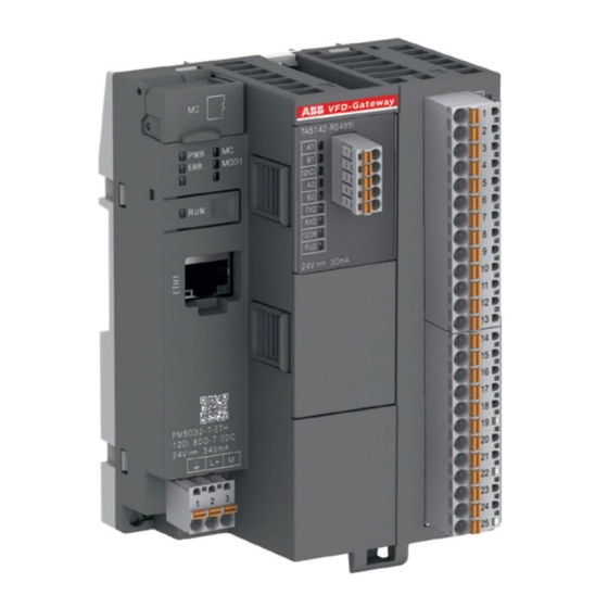
— 2. Installation Contents of this chapter This chapter describes the installation and wiring of the VFD-GATEWAY, showing how to mount the device and where the power/communications connections are made. 2.1 Mounting the VFD-GATEWAY DIN rail according to DIN EN 50022 35 mm, depth 7.5 mm or 15 mm: Mounting with screws M3 (see Appendix for hole fixing dimensions): Note: TA543 option (not included) is ordered separately from the VFD-GATEWAY. - Page 6 The maximum length for an Ethernet segment on twisted pair media is 100 meters. The VFD-GATEWAY supports twisted pair as the physical media in a star topology. All twisted pair media between the Ethernet node and the switch or router must be shorter than 100 meters, including media within patch panels.
- Page 7 120 Ω ¼ W is required at both line ends of the Modbus-RTU network The VFD-GATEWAY has Built in 120 Ω resistor that is enabled from the factory; the VFD-GATEWAY must be at the beginning/end of the network at not mid-network.
- Page 8 Ensure the VFD-GATEWAY is turned off. Press the tab on the side of the module and pull up on the module to remove it from the VFD-GATEWAY: After it is removed, turn the top dip-switches off. They are currently in the on position from the factory.
- Page 9 Use shielded twisted-pair cable with a twisted pair for data and a wire or another pair for signal ground (nominal impedance 100 to 165 ohm, for example Belden 9842) for the wiring. For best immunity, ABB recommends high quality cable. Keep the cable as short as possible.
-
Page 10: Setup
— 3. Setup Contents of this chapter This chapter describes the how to configure the VFD-GATEWAY and drive parameter tables using the VFD-Gateway’s built in web browser configuration pages. 3.1 Drive Setup The VFD-GATEWAY supports the following drives and data connection sizes:... - Page 11 58.06 Comm Control Refresh Settings *58.03 Node Address corresponds to the VFD-GATEWAY Node Settings (see VFD-GATEWAY Settings Web Interface) **It is recommended to set this to 0 to avoid adding delays to the data ***The VFD-GATEWAY only supports these default settings For ACH/Q/S580 the write data starts at 58.108 and First 7 registers must be reads (58.101-58.107)
- Page 12 58.06 Comm Control Refresh Settings *58.03 Node Address corresponds to the VFD-GATEWAY Node Settings (see VFD-GATEWAY Settings Web Interface) **It is recommended to set this to 0 to avoid adding delays to the data ***The VFD-GATEWAY only supports these default settings For ACS880 and DCS880 the write data starts at 58.113 and First 12 registers must be reads (58.101-58.112)
- Page 13 58.06 Comm Control Refresh Settings *58.03 Node Address corresponds to the VFD-GATEWAY Node Settings (see VFD-GATEWAY Settings Web Interface) **It is recommended to set this to 0 to avoid adding delays to the data ***The VFD-GATEWAY only supports these default settings **** 58.107 - 58.112 are set in Hex format in the E-Clipse.
- Page 14 3.6 ABB Drives control profile The VFD-GATEWAY only uses the ABB Drives profile, see below for Control/Status Word and speed scaling instructions: ABB Drives profile Control Word Bit structure Byte Bit 7 Bit 6 Bit 5 Bit 4 Bit 3...
- Page 15 Drive 5 = Integer 60-74 3.8 Ethernet/IP scanner setup Step 1: In the project find the Ethernet Connection, in your controller configuration, that will be used for the VFD-GATEWAY. Step 2: Right click on it and select ‘New Module’ LVD-EOMU02U-EN REVB 04/2022...
- Page 16 Step 3: Set up using the Generic Ethernet Module Skip to Step 5 if using EDS file) Search for generic module and select Generic Ethernet Module and hit create. Note: Use either EDS File or Generic module DO NOT USE BOTH Step 4 : Next populate the required generic module fields per below and press OK.
- Page 17 Step 5: Using the EDS file Search for ABB VFD-GATEWAY and select create. EDS file will need to be installed into the PLC software, to be se- lected. (Note: the EDS file MUST be installed through EDS hardware installation tool before it is available to use.) Note: Use either EDS File or Generic module DO NOT USE BOTH Step 6 : On the next screen, give the module a name and enter the VFD-GATEWAY’s IP address.
- Page 18 Step 7: Select ‘Change’ under module definition. Step 8 : After change is selected the following screen will appear. Select INT and press OK. This will create 75 integers in/out. Drives Input/Output data array mapping is as follows: Drive 1 = Integers 0-14 Drive 2 = Integer 15-29 Drive 3 = Integer 30-44 Drive 4 = Integer 45-59...
- Page 19 The data registers that are not used will be just blank data as a place holder. LVD-EOMU02U-EN REVB 04/2022...
- Page 20 3.9 Configuring the VFD-GATEWAY Web browser interface This chapter describes the how to configure the VFD-GATEWAY using the VFD-Gateway’s’ built in web browser configuration pages. Step 1: Connect and power up: Connect your Ethernet cable, Modbus wiring and apply 24VDC power.
- Page 21 Modbus Node Type for one or each of the 5 drives can be entered in the corresponding Drop-down lists. • The reconnection pause in seconds (default is 1s). This setting controls how often the VFD-Gateway will check for a loss of connection with a Node/drive on the Modbus RTU network. Example, if the value is programmed to 3 seconds and node/drive is powered down, the gateway will check every 3 seconds for this node/drive.
- Page 22 Apply changes by (1) checking the ‘Ready to apply’ button/check box, then (2) Apply setting button: The VFD-GATEWAY will perform a restart (communication will be lost) and the web interface will need to be reconnected with the new IP address.
- Page 23 3.10 Additional screens and settings Changing the VFD-GATEWAY ADMIN password Step 1: From the settings Screen Login as the ADMIN user Step 2: Enter Username: ADMIN; Default Password: ADMIN) click OK. Step 3: Click Change Password. Step 4: The password change box will prompt you to enter the existing password and the new password twice.
- Page 24 Modbus RTU configuration Modbus RTU settings can be found on the Setting screen. Note: The Modbus RTU settings can’t be changed. The Settings screen shows the Active Ethernet/IP settings and the Active Modbus Settings. Note: The Standard User can only view the settings from this page. LVD-EOMU02U-EN REVB 04/2022...
- Page 25 VFD-GATEWAY data tables The VFD-GATEWAY Drive data tables (Drive 1 shown) will display data read and write data within the VFD-GATEWAY and can be used for troubleshooting. The Modbus Node Selected in the Settings Screen will be shown above the Data table.
- Page 26 The Alarm screen shows any Communication errors on each of the Ethernet/IP or Modbus Drive Nodes. The VFD-Gateway Alarms can be represented in the following Output Lights. The wiring shown is optional, each output has a status LED built into the VFD-GATEWAY.
-
Page 27: Troubleshooting
This chapter describes typical errors and conditions that may prevent operation. 4.1 Hard reset of the VFD-GATEWAY In cases where you need to reset the VFD-GATEWAY to factory settings, it can be achieved with the hard reset procedure: 1. Power down the VFD-GATEWAY. - Page 28 • Check Start Stop Speed Reference (refer to drive set up page) for all drives • Make sure the control device is sending the correct information see ABB State Machine (refer to state machine area of the drive manual) •...
-
Page 29: Appendix
— 5. Appendix Contents of this chapter This chapter contains dimensions, technical information and resources for the of the VFD-GATEWAY. 5.1 Dimensions VFD-GATEWAY in (mm) in (mm) in (mm) in (mm) in (mm) in (mm) in (mm) in(mm) in (mm) in (mm) 5.63... - Page 30 5.3 Module Status LEDs State Color LED=ON LED=OFF LED Flashing Power supply Green Power supply Power supply present missing Micro memory Yellow Micro memory Micro memory Micro memory card indication card is in the card is not in the card is in read/ socket socket write state...
- Page 31 60-70ms per drive Continuous read/write time. 100 -110ms per drive The VFD-Gateway is set up to only write data to the drive when the write data changes, this allows us to optimize communication speed. Standards and certifications cUL, CE and RoHS...
- Page 32 ABB does not accept any responsibility whatsoever contents – in whole or in parts – is forbidden without prior for potential errors or possible lack of information in this written consent of ABB.