Table of Contents
Advertisement
Quick Links
Advertisement
Table of Contents

Related Manuals for Asus CROSSBLADE RANGER


Summary of Contents for Asus CROSSBLADE RANGER
- Page 1 CROSSBLADE RANGER...
- Page 2 INCIDENTAL, OR CONSEQUENTIAL DAMAGES (INCLUDING DAMAGES FOR LOSS OF PROFITS, LOSS OF BUSINESS, LOSS OF USE OR DATA, INTERRUPTION OF BUSINESS AND THE LIKE), EVEN IF ASUS HAS BEEN ADVISED OF THE POSSIBILITY OF SUCH DAMAGES ARISING FROM ANY DEFECT OR ERROR IN THIS MANUAL OR PRODUCT.
-
Page 3: Table Of Contents
Contents Safety information ...................... vi About this guide ......................vii CROSSBLADE RANGER specifications summary ..........ix Package contents ..................... xiii Installation tools and components ................. xiv Chapter 1: Product Introduction Special features..................1-1 1.1.1 Product highlights................ 1-1 1.1.2 ROG Gaming Features ............... 1-2 1.1.3... - Page 4 3.6.8 ROG Effects ................3-26 Monitor menu ................... 3-27 Boot menu ....................3-30 Tool menu ....................3-36 3.9.1 ASUS EZ Flash 2 Utility ............3-36 3.9.2 Secure Erase ................3-36 3.9.3 Setup Animator [Disabled] ............3-37 3.9.4 Graphics Card Information ............3-37 ............
- Page 5 GameFirst III ..................... 4-30 KeyBot....................... 4-33 4.10 ASUS Media Streamer ................4-35 4.11 ASUS Disk Unlocker ................4-37 4.12 RAMDisk ....................4-38 4.13 MemTweakIt ....................4-41 4.14 ROG CPU-Z ....................4-43 Chapter 5: RAID support RAID configurations .................. 5-1 ................5-1 5.1.2...
-
Page 6: Safety Information
Safety information Electrical safety before relocating the system. When adding or removing devices to or from the system, ensure that the power cables for the devices are unplugged before the signal cables are connected. If possible, disconnect all power cables from the existing system before you add a device. Before connecting or removing signal cables from the motherboard, ensure that all power cables are unplugged. -
Page 7: About This Guide
Refer to the following sources for additional information and for product and software updates. ASUS website The ASUS website (www.asus.com) provides updated information on ASUS hardware and software products. Optional documentation that may have been added by your dealer. These documents are not part of the... - Page 8 Conventions used in this guide To ensure that you perform certain tasks properly, take note of the following symbols used throughout this manual. DANGER/WARNING: Information to prevent injury to yourself when trying to complete a task. CAUTION: Information to prevent damage to the components when trying to complete a task IMPORTANT: Instructions that you MUST follow to complete a task.
-
Page 9: Crossblade Ranger Specifications Summary
* The max. 64GB memory capacity can be supported with DIMMs of Memory 16GB (or above). ASUS will update the QVL once the DIMMs are available on the market. ** Hyper DIMM support is subject to the physical characteristics of individual CPUs. - Page 10 CROSSBLADE RANGER specifications summary ROG SupremeFX Audio 8-Channel High Definition Audio - SupremeFX Shielding Technology - ELNA ® Premium Audio Capacitors - Content Protection for Full Rate lossless DVD Audio, Blu-ray DVD, and HD-DVD audio content playback - Jack-detection, Multi-streaming, and Front Panel Jack-...
- Page 11 - ASUS Fanless Design: Stylish Heatpipe & MOS Heatsink Solution - ASUS Fan Xpert3 ASUS EZ DIY - ASUS UEFI BIOS EZ Mode featuring friendly graphics user interface - ASUS CrashFree BIOS 3 - ASUS EZ Flash 2 ASUS Q-Design...
- Page 12 1 x Sonic SoundStage button 1 x KeyBot button 64 Mb Flash ROM, UEFI AMI BIOS, PnP, DMI 2.7, WfM 2.0, SM BIOS 2.7, ACPI 5.0, Multi-language BIOS, ASUS EZ Flash 2, ASUS BIOS Features F12 PrintScreen, F3 Shortcut functions, and ASUS DRAM SPD...
-
Page 13: Package Contents
Package contents Check your motherboard package for the following items. ROG CROSSBLADE RANGER Motherboard 2 x 2-in-1 SATA 6 Gb/s cables Cables 1 x I/O Shield 1 x 12-in-1 ROG cable label Accessories 1 x 2-in-1 Q-Connector kit 1 x ROG Door Hanger... -
Page 14: Installation Tools And Components
Installation tools and components 1 bag of screws Philips (cross) screwdriver PC chassis Power supply unit AMD FM2+ CPU AMD FM2+ compatible CPU Fan DDR3 DIMM SATA hard disk drive SATA optical disc drive (optional) Graphics card (optional) The tools and components in the table above are not included in the motherboard package. -
Page 15: Chapter 1: Product Introduction
This motherboard offers you the strategic USB 3.0 accessibility for both the front and rear panels, allowing you to experience the convenience of the latest plug and play connectivity solution at speed up to ten times faster than USB 2.0. ASUS CROSSBLADE RANGER... -
Page 16: Rog Gaming Features
GameFirst III ASUS GameFirst III is a network management software that features four preset packet user’s need. Users can also manually allocate bandwidth and adjust priority settings of each application to run faster and smoother. -
Page 17: Rog Exclusive Features
ASUS Special Features AI Suite 3 With its user-friendly interface, ASUS AI Suite 3 consolidates all the exclusive ASUS features into one simple-to-use software package. It allows you to supervise fan speed control, voltage and sensor readings. This all-in-one software offers diverse and ease to use functions, with no need to switch back and forth between different utilities. -
Page 18: Rog Rich Bundled Software
1.1.5 ROG rich bundled software KeyBot KeyBot is a built-in microprocessor that provides instant upgrade to your keyboard. You can directly to BIOS mode. This feature supports USB keyboards only. Kaspersky ® Anti-Virus ® Kaspersky Anti-Virus Personal offers premium anti virus protection for individual users and ®... -
Page 19: Motherboard Overview
Failure to do so may cause severe damage to the motherboard, peripherals, or components. ASUS CROSSBLADE RANGER... -
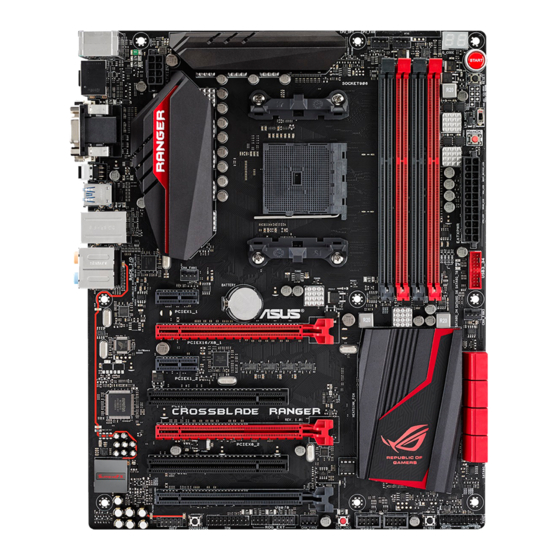
Page 20: Motherboard Layout
1.2.2 Motherboard layout CPU_OPT CPU_FAN KBMS_USB12 Q_CODE RESET EATX12V MemOK! BIOS_FLBK USB3_12 LAN_USB3_E12 Intel AUDIO I211 CHA_FAN1 PCIEX1_1 BATTERY 1042A CHA_FAN3 PCIEX16/X8_1 PCIEX1_2 ® PCI1 A88X FCH Super PCIEX8_2 PCI2 BIOS HD_LED FLBK_LED PCIEX4_3 DRCT USB56 USB34 KEYBOT_LED ROG_EXT CHA_FAN2 CLR_CMOS PANEL SOUNDSTAGE... - Page 21 1-37 21. Clear CMOS button (CLR_CMOS) 1-25 22. ROG Extension connector (18-1 pin ROG_EXT) 1-42 23. TPM connector (20-1 pin TPM) 1-42 24. Sonic SoundStage button (SOUNDSTAGE) 1-26 25. Front panel audio connector (10-1 pin AAFP) 1-38 ASUS CROSSBLADE RANGER...
-
Page 22: Central Processing Unit (Cpu)
The motherboard comes with an AMD FM2+ socket designed for AMD A-series and Athlon™ Series processors. CROSSBLADE RANGER CPU socket FM2+ correct orientation. DO NOT force the APU into the socket to prevent bending the pins and damaging the APU! -
Page 23: System Memory
The motherboard comes with four Double Data Rate 3 (DDR3) Dual Inline Memory Modules (DIMM) slots. A DDR3 module is notched differently from a DDR or DDR2 module. DO NOT install a DDR or DDR2 memory module to the DDR3 slot. CROSSBLADE RANGER 240-pin DDR3 DIMM sockets Recommended memory configurations ASUS CROSSBLADE RANGER... - Page 24 Memory configurations You may install 1 GB, 2 GB, 4 GB and 8 GB unbuffered and non-ECC DDR3 DIMMs into the DIMM sockets. excess memory from the higher-sized channel is then mapped for single-channel operation. recommend that you install memory modules of the same version or date code (D/C) from the same vendor.
- Page 25 CROSSBLADE RANGER Motherboard Qualified Vendors Lists (QVL) DDR3 2666 (O.C.) MHz capability DIMM socket support (optional) Chip Chip Vendors Part No. Size Timing Voltage Brand 1DIMM 2DIMMs 4DIMMs CORSAIR CMD16GX3M4A2666C10 (Ver4.13) 4GB 10-12-12-31 1.65V G.SKILL F3-2666C11Q-16GTXD(XMP) 16GB (4x4GB) DS 11-13-13-35 1.65V DDR3 2400 (O.C.) MHz capability...
- Page 26 DDR3 2133 MHz capability DIMM socket support (optional) Vendors Part No. Size Chip Brand Chip NO. Timing Voltage 1DIMM 2DIMMs 4DIMMs AX3U2133GC2G9B-DG2 1.55~ A-DATA 9-11-9-27 (XMP) 1.75V CMT16GX3M4X2133C9 16GB CORSAIR 9-11-10-27 1.50V (XMP1.3) (4GBx4 ) CMT4GX3M2A2133C9 CORSAIR 9-10-9-24 1.65V (XMP) (2x2GB) CMT4GX3M2B2133C9 CORSAIR...
- Page 27 AX3U1866XW8G10 DS - 10-11-10-30 1.5V (2x8GB ) PATRIOT PV138G186C9KPD000326 DS - 1.5V Team TLD34G1866H9KBK DS - 9-11-9-27 1.5V Team TLD38G1866HC10SBK DS - 10-11-10-30 1.5V BLT4G3D1869DT1TX0.13FKD CRUCIAL DS - 9-9-9-27 1.5V (XMP) KINGSTON KHX18C10T3K4/32X DS - 1.5V ASUS CROSSBLADE RANGER 1-13...
- Page 28 DDR3 1600 MHz capability DIMM socket support Chip (optional) Vendor Part No. Size Chip NO. Timing Voltage Brand 1DIMM 2DIMMs 4DIMMs A-DATA AM2U16BC2P1 A-DATA 3CCD-1509A EL1126T - AX3U1600XB2G79-2X A-DATA 7-9-7-21 1.55V-1.75V (XMP) (2x2GB) A-DATA AM2U16BC4P2 A-DATA 3CCD-1509A EL1126T - AX3U1600GC4G9-2G A-DATA 9-9-9-24 1.55V-1.75V...
- Page 29 M2P2G64CB8HC9N-DG Elixir (XMP) M2X8G64CB8HB5N-DG Elixir Elixir1213 N2CB4G8BOBN-DG (XMP) Mushkin 998659 (XMP) 9-9-9-24 (3x2GB) Mushkin 998659 (XMP) 9-9-9-24 (3x2GB) ~1.6V 32GB PATRIOT PGD316G1600ELK (XMP) 9-9-9-24 1.65V (8GBx4) PATRIOT PGS34G1600LLKA 7-7-7-20 1.7V (2x2GB) (continued on the next page) ASUS CROSSBLADE RANGER 1-15...
- Page 30 DDR3 1600 MHz capability DIMM socket support (optional) Vendor Part No. Size Chip Brand Chip NO. Timing Voltage 1DIMM 2DIMMs 4DIMMs Silicon SP002GBLTU160V02 SS S-POWER 20YT5NG-1201 Power (XMP) Silicon SP004GBLTU160V02 DS S-POWER 20YT5NG-1201 Power (XMP) Apacer 78.B1GE3.9L10C DS Apacer KZZC AM5D5908DEQSCK 16GB KINGSTON KHX16C9K2/16...
- Page 31 Kingmax KKB8FNWBFGNX-27A Kingmax FLFE85F-C8KF9 CAES Kingmax KFC8FMFXF-DXX-15A Kingmax FLFE85F-C8KL9 NAES Kingmax KFC8FNLXF-DXX-15A Kingmax FLFE85F-C8KM9 NAES Kingmax KFC8FNMXF-BXX-15A Kingmax FLFE85F-B8KL9 NEES Kingmax KKB8FNWBFGNX-26A Kingmax FLFF65F-C8KL9 NEES Kingmax KFC8FNLXF-DXX-15A Kingmax FLFF65F-C8KM9 NEES Kingmax KFC8FNMXF-BXX-15A (continued on the next page) ASUS CROSSBLADE RANGER 1-17...
- Page 32 DDR3 1333 MHz capability DIMM socket support (optional) Vendor Part No. Size Chip Brand Chip NO. Timing Voltage 1DIMM 2DIMMs 4DIMMs KVR1333D3N9/1G KINGSTON ELPIDA J1108BDBG-DJ-F 1.5V KVR1333D3N9/2G KINGSTON Hynix H5TQ2G83AFRH9C KINGSTON KVR1333D3S8N9/2G Micron IID77 D9LGK 1.5V KVR1333D3S8N9/2G-SP KINGSTON ELPIDA J2108BCSE-DJ-F 1.5V KVR1333D3N9/2G KINGSTON...
- Page 33 Transcend 8G DDR3 1333 DIMM CL9 HMDD302GU648S1B9C-MEX 2GB ERTH 256X8DDR3 WT 1.5V HMDD304GU648S1B9C-MEX 4GB UUJK 512X8DDR3 WT 1.5V HMDD308GU648D1B9C-MEX 8GB FFCT 512X8DDR3 WT 1.5V TEAM TED34G1333HC9BK 9-9-9-24 TEAM TED38G1333HC9BK 9-9-9-24 1.5V Asint SLA304G08-EDJ1B Asint 304G08-DJ1B1301 - ASUS CROSSBLADE RANGER 1-19...
- Page 34 We suggest that you install the modules into slots A2 and B2 for better compatibility. Supports four (4) modules inserted into both the red and black slots as two pairs Visit the ASUS website for the latest QVL. 1-20 Chapter 1: Product introduction...
-
Page 35: Expansion Slots
PCIEX16/X8_1 PCIEX1_2 PCI1 PCIEX8_2 PCI2 PCIEX4_3 Slot No. Slot Description PCIe 2.0 x1_1 slot PCIe 3.0/2.0 x16/x8_1 slot PCIe 2.0 x1_2 slot PCI slot 1 PCIe 3.0/2.0 x8_2 slot PCI slot 2 PCIe 2.0 x4_3 slot ASUS CROSSBLADE RANGER 1-21... - Page 36 PCIe operating mode VGA Configuration Single VGA CrossFireX™ 3-WAY CrossFireX™ PCIEX16/X8_1 PCIEX8_2 PCIEX4_3 using multiple graphics cards for better thermal environment. PCIEX16/X8_1 slot switches to x8 mode when PCIEX8_2 slot is occupied. IRQ assignments for this motherboard PCIE x16 – –...
-
Page 37: Onboard Buttons And Switches
The button also lights up when the system is plugged to a power source indicating that you should shut down the system and unplug the power cable before removing or installing any motherboard component. CROSSBLADE RANGER Power-on button RESET button (RESET) Press the reset button to reboot the system. - Page 38 If the installed DIMMs still fail to boot after the whole tuning Vendors Lists) in this user manual or on the ASUS website at www.asus.com. continues memory tuning after turning on the computer. To stop memory tuning, turn off the computer and unplug the power cord for about 5–10 seconds.
- Page 39 Clear CMOS button (CLR_CMOS) Press this button to clear the BIOS setup information only when the systems hangs due to overclocking. CROSSBLADE RANGER Clear CMOS button KeyBot button (KeyBot) Press this button to activate the KeyBot feature. KEYBOT CROSSBLADE RANGER KeyBot button The KeyBot feature supports USB keyboards only.
- Page 40 Sonic SoundStage button (SOUNDSTAGE) Press this button to activate the Sonic SoundStage feature. SOUNDSTAGE CROSSBLADE RANGER Sonic SoundStage button when you press the Sonic SoundStage button. 4.6 ROG audio features of this user guide. Slow Mode switch Slow Mode switch allows your system to provide better overclocking margins when using the LN2 cooling system.
-
Page 41: Jumpers
When enabled, the LN2 Mode jumper allows your system to eliminate the cold bugs in the processor during POST. It allows the processor to run at an extremely low temperature and helps the system boot fast. LN2_MODE CROSSBLADE RANGER LN2 mode setting 1.2.8 Onboard LEDs Hard Disk LED (HD_LED) The Hard Disk LED is designed to indicate the hard disk activity. - Page 42 BOOT_DEVICE_LED VGA_LED DRAM_LED CPU_LED CROSSBLADE RANGER CPU/DRAM/ BOOT_DEVICE/VGA/HD LED KeyBot LED (KEYBOT_LED) This LED lights up when the KeyBot button is pressed. KEYBOT_LED CROSSBLADE RANGER KeyBot LED 1-28 Chapter 1: Product introduction...
- Page 43 USB BIOS Flashback LED (FLBK_LED) FLBK_LED CROSSBLADE RANGER BIOS Flashback LED Q-Code LED (Q_CODE) The Q-Code LED design provides you with a 2-digit error code that displays the system status. Refer to the Q-Code table on the following page for details.
- Page 44 Q-Code table Code Description Not used Power on. Reset type detection (soft/hard). AP initialization before microcode loading System Agent initialization before microcode loading PCH initialization before microcode loading Microcode loading AP initialization after microcode loading System Agent initialization after microcode loading PCH initialization after microcode loading Cache initialization 0C –...
- Page 45 Reserved for future AMI progress codes S3 Resume Failed S3 Resume PPI not Found S3 Resume Boot Script Error S3 OS Wake Error EC – EF Reserved for future AMI error codes (continued on the next page) ASUS CROSSBLADE RANGER 1-31...
- Page 46 Q-Code table Code Description Recovery condition triggered by user (Forced recovery) Recovery process started F5 – F7 Reserved for future AMI progress codes Recovery PPI is not available Recovery capsule is not found Invalid recovery capsule FB – FF Reserved for future AMI error codes DXE Core is started NVRAM initialization Installation of the PCH Runtime Services...
- Page 47 Legacy Boot event Exit Boot Services event Runtime Set Virtual Address MAP Begin Runtime Set Virtual Address MAP End Legacy Option ROM Initialization System Reset USB hot plug PCI bus hot plug (continued on the next page) ASUS CROSSBLADE RANGER 1-33...
- Page 48 Q-Code table Code Description Clean-up of NVRAM B8– BF Reserved for future AMI codes CPU initialization error System Agent initialization error PCH initialization error Some of the Architectural Protocols are not available PCI resource allocation error. Out of Resources No Space for Legacy Option ROM No Console Output Devices are found No Console Input Devices are found Invalid password...
-
Page 49: Internal Connectors
RSATA_RXN2 RSATA_RXP1 RSATA_RXP2 CROSSBLADE RANGER SATA 6.0Gb/s connectors AHCI] by default. If you intend to create a Serial ATA RAID set using these connectors, set the SATA Mode item in the BIOS to [RAID]. Refer to section SATA Configuration for details. - Page 50 IntA_P2_D+ CROSSBLADE RANGER USB3.0 front panel connector The USB 3.0 module is purchased separately. You can connect the ASUS front panel USB 3.0 bracket to this connector to obtain the front panel USB 3.0 solution. 1-36 Chapter 1: Product introduction...
- Page 51 USB34 PIN 1 PIN 1 PIN 1 CROSSBLADE RANGER USB2.0 connectors Never connect a 1394 cable to the USB connectors. Doing so will damage the motherboard! install the Q-Connector (USB) to the USB connector onboard if your chassis supports front panel USB ports.
- Page 52 Legacy AC’97 pin definition compliant definition CROSSBLADE RANGER Front panel audio connector connector, set the Front Panel Type item in the BIOS setup to [HD] or [AC97]. Direct connector (2-pin DRCT) This connector is for the chassis-mounted button that supports the DirectKey function.
- Page 53 CHA_FAN1 CHA_FAN3 CHA_FAN2 CROSSBLADE RANGER Fan connectors inside the system may damage the motherboard components. These are not jumpers! Do not place jumper caps on the fan connectors! The CPU_FAN connector supports the CPU fan of maximum 1A (12 W) fan power.
- Page 54 The system may become unstable or may not boot up if the power is inadequate. power or above to ensure the system stability. refer to the Recommended Power Supply Wattage Calculator at http://support.asus. com/PowerSupplyCalculator/PSCalculator.aspx?SLanguage=en-us for details. 1-40...
- Page 55 PIN 1 +HDD_LED- PWR_SW RESET CROSSBLADE RANGER System panel connector This 2-pin connector is for the system power LED. Connect the chassis power LED cable to this connector. The system power LED lights up when you turn on the system power, and blinks when the system is in sleep mode.
- Page 56 This connector is for the Front Base. ROG_EXT CROSSBLADE RANGER ROG extension connector www.asus.com for more information about the Front Base. TPM connector (20-1 pin TPM) This connector supports a Trusted Platform Module (TPM) system, which securely the network security, protects digital identities, and ensures platform integrity.
-
Page 57: Chapter 2: Basic Installation
The diagrams in this section are for reference only. The motherboard layout may vary with models, but the installation steps are the same for all models. Install the ASUS Q-Shield to the chassis rear I/O panel. Place the motherboard into the chassis, ensuring that its rear I/O ports are aligned to the chassis’... - Page 58 Place nine screws into the holes indicated by circles to secure the motherboard to the chassis. DO NOT over tighten the screws! Doing so can damage the motherboard. Chapter 2: Basic Installation...
-
Page 59: Apu Installation
APU installation Ensure that you use a APU designed for the FM2+ socket. The APU fits in only one correct orientation. DO NOT force the APU into the socket to prevent bending the pins and damaging the APU! ASUS CROSSBLADE RANGER... -
Page 60: Apu Heatsink And Fan Assembly Installation
2.1.3 APU heatsink and fan assembly installation Apply the Thermal Interface Material to the APU heatsink and APU before you install the heatsink and fan if necessary. To install the APU heatsink and fan assembly Chapter 2: Basic Installation... - Page 61 To uninstall the APU heatsink and fan assembly ASUS CROSSBLADE RANGER...
-
Page 62: Dimm Installation
2.1.4 DIMM installation To remove a DIMM Chapter 2: Basic Installation... -
Page 63: Atx Power Connection
2.1.5 ATX Power connection ASUS CROSSBLADE RANGER... -
Page 64: Sata Device Connection
2.1.6 SATA device connection Chapter 2: Basic Installation... -
Page 65: Front I/O Connector
2.1.7 Front I/O Connector To install ASUS Q-Connector To install USB 2.0 connector To install front panel audio connector AAFP USB 2.0 To install USB 3.0 connector USB 3.0 ASUS CROSSBLADE RANGER... -
Page 66: Expansion Card Installation
2.1.8 Expansion Card installation To install PCIe x16 cards To install PCIe x1 cards To install PCI cards 2-10 Chapter 2: Basic Installation...