Dell PowerEdge R630 Owner's Manual
Hide thumbs
Also See for PowerEdge R630:
- Owner's manual (207 pages) ,
- Technical manual (59 pages) ,
- Installing manual (18 pages)

Related Manuals for Dell PowerEdge R630


Summary of Contents for Dell PowerEdge R630
- Page 1 Dell PowerEdge R630 Owner's Manual Regulatory Model: E26S Series Regulatory Type: E26S001 June 2022 Rev. A08...
- Page 2 A WARNING indicates a potential for property damage, personal injury, or death. © 2014- 2020 Dell Inc. or its subsidiaries. All rights reserved. Dell Technologies, Dell, and other trademarks are trademarks of Dell Inc. or its subsidiaries. Other trademarks may be trademarks of their respective owners.
-
Page 3: Table Of Contents
Contents Chapter 1: Dell PowerEdge R630 system overview.................8 Supported configurations for PowerEdge R630 system................... 8 Front panel ..................................10 10 x 2.5-inch hard drive chassis..........................10 Eight x 2.5-inch hard drive chassis...........................11 24 x 1.8-inch hard drive chassis..........................13 LCD panel..................................14 Back panel features................................ - Page 4 System Setup..................................41 Viewing System Setup............................... 42 System Setup details..............................42 System BIOS.................................42 iDRAC Settings utility..............................65 Device Settings................................66 Dell Lifecycle Controller..............................66 Embedded systems management..........................67 Boot Manager..................................67 Viewing Boot Manager............................... 67 Boot Manager main menu............................67 PXE boot..................................... 68 Chapter 6: Installing and removing system components.............. 69 Safety instructions................................69...
- Page 5 Installing a hot swappable hard drive into a hot swappable hard drive carrier..........88 Removing a 1.8-inch hard drive from a hard drive carrier................. 89 Installing a 1.8-inch hard drive into a hard drive carrier..................89 Optical drive (optional)..............................90 Removing the optional optical drive........................
- Page 6 Chapter 8: Using system diagnostics..................175 Dell Embedded System Diagnostics..........................175 Running the Embedded System Diagnostics from Boot Manager..............175 Running the Embedded System Diagnostics from the Dell Lifecycle Controller........175 System diagnostics controls........................... 175 Chapter 9: Jumpers and connectors ..................177 System board jumper settings............................
- Page 7 Troubleshooting a tape backup unit..........................191 Troubleshooting a drive or SSD........................... 192 Troubleshooting a storage controller..........................193 Troubleshooting expansion cards..........................193 Troubleshooting processors............................194 Chapter 11: Getting help......................196 Contacting Dell.................................196 Documentation feedback...............................196 Accessing system information by using QRL......................196 Quick Resource Locator for R630......................... 197 Contents...
-
Page 8: Chapter 1: Dell Poweredge R630 System Overview
● Four optional NVMe Express Flash PCIe SSDs ● 24 DIMM slots supporting up to 1536 GB of memory ● Two AC or DC redundant power supply units NOTE: The Dell PowerEdge R630 system supports hot swappable hard drives. Topics: • Supported configurations for PowerEdge R630 system •... - Page 9 Figure 1. Supported configurations for PowerEdge R630 system Dell PowerEdge R630 system overview...
-
Page 10: Front Panel
The hot swappable hard drives are accessible from the front panel. 10 x 2.5-inch hard drive chassis Figure 2. Front panel features of the 10 x 2.5-inch hard drive PowerEdge R630 chassis 1. Diagnostic indicators 2. -
Page 11: Eight X 2.5-Inch Hard Drive Chassis
Table 1. Front panel features of the 10 x 2.5-inch hard drive PowerEdge R630 chassis (continued) Item Indicator, Button, or Icon Description Connector Press to toggle the system ID on or off. If the system stops responding during POST, press and hold the system ID button for more than five seconds to enter BIOS progress mode. - Page 12 Table 2. Front panel features of the eight x 2.5-inch PowerEdge R630 hard drive chassis Item Indicator, Button, or Icon Description Connector Power-on indicator, power Enables you to know the power status of the system. The button power indicator turns on when the system power is on. The power button controls the power supply output to the system.
-
Page 13: 24 X 1.8-Inch Hard Drive Chassis
Table 2. Front panel features of the eight x 2.5-inch PowerEdge R630 hard drive chassis (continued) Item Indicator, Button, or Icon Description Connector Quick Sync Indicates a Quick Sync enabled system. The Quick Sync feature is optional and needs a Quick Sync bezel. This feature allows management of the system by using mobile devices. -
Page 14: Lcd Panel
The LCD panel of your system provides system information, status, and error messages to indicate if the system is functioning correctly or if the system needs attention. For more information about error messages, see the Dell Event and Error Messages Reference Guide at Dell.com/openmanagemanuals >OpenManage software. - Page 15 LCD message with an SEL entry. Select Simple to view LCD error messages in a simplified user-friendly description. For more information about error messages, see the Dell Event and Error Messages Reference Guide at Dell.com/ openmanagemanuals > OpenManage software.
-
Page 16: Back Panel Features
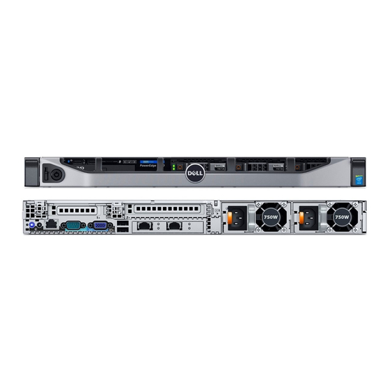
4. PCIe expansion card slot (riser 1) 5. Serial connector 6. Video connector 7. USB ports (2) 8. PCIe expansion card slot (riser 2) 9. Ethernet connectors (4) 10. Power supply unit (PSU1) 11. Power supply unit (PSU2) Dell PowerEdge R630 system overview... - Page 17 ● Two 1100 W DC PSUs ● Two 750 W mixed mode PSUs PSU2 ● Two 495 W, 750 W, or 1100 W AC PSUs ● Two 1100 W DC PSUs ● Two 750 W mixed mode PSUs Dell PowerEdge R630 system overview...
-
Page 18: Three-Riser Chassis
The port is available for use only if the iDRAC8 Enterprise license is installed on your system. LP PCIe expansion card slot Enables you to connect a low profile LP PCIe expansion card. (riser 1) See the Expansion card installation guidelines section. Dell PowerEdge R630 system overview... -
Page 19: Diagnostic Indicators On The Front Panel
No diagnostic indicators are lit when the system is turned off. To start the system, plug it into a working power source and press the power button. Table 7. Diagnostic indicators Icon Description Condition Corrective action Health indicator The indicator turns solid blue if the None required. system is in good health. Dell PowerEdge R630 system overview... - Page 20 Check the System Event Log or system messages for the specific issue. For more information ● When the system is turned on. about error messages, see the Dell Event and ● When the system is in standby. Error Messages Reference Guide at Dell.com/ ●...
-
Page 21: Hard Drive Indicator Codes
Flashes amber four times per second Drive failed Flashes green slowly Drive rebuilding Steady green Drive online Flashes green for three seconds, amber for three Rebuild stopped seconds, and then turns off after six seconds Dell PowerEdge R630 system overview... -
Page 22: Usata Ssd Indicator Codes
Flashes green, amber, and turns off Predicted drive failure Flashes amber four times per second Drive failed Steady green Drive online Flashes green for three seconds, amber for three Rebuild aborted seconds, and turns off after six seconds Dell PowerEdge R630 system overview... -
Page 23: Nic Indicator Codes
AC power supply units (PSUs) have an illuminated translucent handle that serves as an indicator and DC PSUs have an LED that serves as an indicator. The indicator shows whether power is present or a power fault has occurred. Dell PowerEdge R630 system overview... - Page 24 For AC PSUs, use only PSUs with the Extended Power Performance (EPP) label on the back. NOTE: Mixing PSUs from previous generations of Dell PowerEdge servers can result in a PSU mismatch condition or failure to turn the system on. Flashing amber Indicates a problem with the PSU.
-
Page 25: Idrac Direct Led Indicator Codes
The iDRAC Direct LED indicator lights up to indicate that the port is connected and is being used as a part of the iDRAC subsystem. NOTE: The iDRAC Direct LED indicator does not turn on when the USB port is used in the USB mode. Dell PowerEdge R630 system overview... - Page 26 Indicates that the laptop is connected. Solid green for two seconds Flashing green (on for two seconds Indicates that the laptop connected is recognized. and off for two seconds) Turns off Indicates that the laptop is unplugged. Dell PowerEdge R630 system overview...
-
Page 27: Quick Sync Indicator Codes
Tag are found on the front of the system by pulling out the information tag. Alternatively, the information may be on a sticker on the chassis of the system. This information is used by Dell to route support calls to the appropriate personnel. -
Page 28: Chapter 2: Documentation Resources
This section provides information about the documentation resources for your system. To view the document that is listed in the documentation resources table: ● From the Dell EMC support site: 1. Click the documentation link that is provided in the Location column in the table. - Page 29 Methods to download firmware and drivers section in this document. Managing your system For information about system management https://www.dell.com/poweredgemanuals software offered by Dell, see the Dell OpenManage Systems Management Overview Guide. For information about setting up, using, and www.dell.com/openmanagemanuals >...
-
Page 30: Chapter 3: Technical Specifications
• PSU specifications • System battery specifications • Expansion bus specifications • Memory specifications • Drive specifications • Ports and connectors specifications • Video specifications • Environmental specifications Chassis dimensions Figure 15. Chassis dimensions of PowerEdge R630 system Technical specifications... -
Page 31: Chassis Weight
17.4 kg (38.36 lb) Processor specifications The PowerEdge R630 system supports up to two Intel Xeon E5-2600 v3 or v4 product family processors. PSU specifications The PowerEdge R630 system supports up to two AC or DC redundant power supply units (PSUs). -
Page 32: System Battery Specifications
Expansion bus specifications The PowerEdge R630 system supports PCI express (PCIe) generation 3 expansion cards, which must be installed on the system board by using expansion card risers. This system supports three types of expansion card risers. The following table provides detailed information about the expansion card riser specifications: Table 20. -
Page 33: Optical Drive
● Four 10 Gbps Serial connector The serial connector connects a serial device to the system. The PowerEdge R630 system supports one serial connector on the back panel, which is a 9-pin connector, Data Terminal Equipment (DTE), 16550-compliant. VGA ports The Video Graphic Array (VGA) port enables you to connect the system to a VGA display. -
Page 34: Video Specifications
Video specifications The PowerEdge R630 system supports Integrated VGA controller with 16 MB capacity. Table 23. Resolution information for video modes Resolution Refresh rate (Hz) Color depth (bit) 640 X 480 60, 70 8, 16, 32 800 X 600 60, 75, 85... -
Page 35: Particulate And Gaseous Contamination Specifications
Table 27. Maximum shock specifications (continued) Maximum shock Specifications Storage Six consecutively executed shock pulses in the positive and negative x, y, and z axes (one pulse on each side of the system) of 71 G for up to 2 ms. Table 28. -
Page 36: Standard Operating Temperature
Table 31. Gaseous contamination specifications Gaseous contamination Specifications Copper coupon corrosion rate <300 Å/month per Class G1 as defined by ANSI/ ISA71.04-1985. Silver coupon corrosion rate <200 Å/month as defined by AHSRAE TC9.9. NOTE: Maximum corrosive contaminant levels measured at ≤50% relative humidity. Standard operating temperature Table 32. -
Page 37: Expanded Operating Temperature Restrictions
● 145 W and Workstation CPU (160 W) processors are not supported. ● Two power supply units (PSUs) are needed and one PSU failure is not supported. ● Non-Dell qualified peripheral cards and/or peripheral cards greater than 25 W are not supported. ● PCIe SSD and 1.8-inch SSDs are not supported. -
Page 38: Chapter 4: Initial System Setup And Configuration
The Integrated Dell Remote Access Controller (iDRAC) is designed to make system administrators more productive and improve the overall availability of Dell EMC systems. iDRAC alerts administrators to system issues, helps them perform remote system management, and reduces the need for physical access to the system. -
Page 39: Options To Install The Operating System
NOTE: You must have iDRAC credentials to log in to iDRAC. For more information about logging in to iDRAC and iDRAC licenses, see the latest Integrated Dell Remote Access Controller User's Guide at Dell.com/idracmanuals. Options to install the operating system... - Page 40 Downloading the drivers and firmware Dell EMC recommends that you download and install the latest BIOS, drivers, and systems management firmware on your system. Ensure that you clear the web browser cache before downloading the drivers and firmware. 1. Go to Dell.com/support/drivers.
-
Page 41: Chapter 5: Pre-Operating System Management Applications
Options to manage the pre-operating system applications Your system has the following options to manage the pre-operating system applications: ● System Setup ● Boot Manager ● Dell Lifecycle Controller ● Preboot Execution Environment (PXE) Related concepts System Setup Boot Manager... -
Page 42: Viewing System Setup
The iDRAC settings utility is an interface to set up and configure the iDRAC parameters by using UEFI (Unified Extensible Firmware Interface). You can enable or disable various iDRAC parameters by using the iDRAC settings utility. For more information about this utility, see Integrated Dell Remote Access Controller User’s Guide at Dell.com/idracmanuals. - Page 43 Processor Settings SATA Settings Integrated Devices Serial Communication System Profile Settings Miscellaneous Settings iDRAC Settings utility Device Settings System Security Related tasks Viewing System BIOS Viewing System BIOS To view the System BIOS screen, perform the following steps: 1. Turn on, or restart your system. 2.
- Page 44 Option Description Miscellaneous Specifies options to change the system date, time, and so on. Settings Related references System BIOS Related tasks Viewing System BIOS Boot Settings You can use the Boot Settings screen to set the boot mode to either BIOS or UEFI. It also enables you to specify the boot order.
- Page 45 ● Operating systems must be UEFI-compatible to be installed from the UEFI boot mode. DOS and 32-bit operating systems do not support UEFI and can only be installed from the BIOS boot mode. ● For the latest information about supported operating systems, go to Dell.com/ossupport. Related references...
- Page 46 Changing the boot order You may have to change the boot order if you want to boot from a USB key or an optical drive. The following instructions may vary if you have selected BIOS for Boot Mode. 1. On the System Setup Main Menu screen, click System BIOS > Boot Settings. 2.
- Page 47 Network Settings screen details The Network Settings screen details are explained as follows: Option Description PXE Device n (n Enables or disables the device. When enabled, a UEFI boot option is created for the device. = 1 to 4) PXE Device n Enables you to control the configuration of the PXE device.
- Page 48 Option Description ISCSI Device n (n Enables or disables the iSCSI device. When disabled, a UEFI boot option is created for the iSCSI device = 1 to 4) automatically. System Security You can use the System Security screen to perform specific functions such as setting the system password, setup password and disabling the power button.
- Page 49 Option Description TPM Security NOTE: The TPM menu is available only when the TPM module is installed. Enables you to control the reporting mode of the TPM. The TPM Security option is set to Off by default. You can only modify the TPM Status, TPM Activation, and Intel TXT fields if the TPM Status field is set to either On with Pre-boot Measurements or On without Pre-boot Measurements.
- Page 50 NOTE: If your operating system begins to load before you press F2, wait for the system to finish booting, and then restart your system and try again. 3. On the System Setup Main Menu screen, click System BIOS. 4. On the System BIOS screen, click System Security. 5.
- Page 51 Using your system password to secure your system If you have assigned a setup password, the system accepts your setup password as an alternate system password. 1. Turn on or reboot your system. 2. Type the system password and press Enter. When Password Status is set to Locked, type the system password and press Enter when prompted at reboot.
- Page 52 System Information You can use the System Information screen to view system properties such as Service Tag, system model name, and the BIOS version. Related references System Information details System BIOS Related tasks Viewing System Information Viewing System Information To view the System Information screen, perform the following steps: 1.
- Page 53 Related references System Information System Information details Related tasks Viewing System Information Memory Settings You can use the Memory Settings screen to view all the memory settings and enable or disable specific memory functions, such as memory testing and node interleaving. Related references Memory Settings details System BIOS...
- Page 54 Specifies the memory operating mode. The options available are Optimizer Mode, Advanced ECC Operating Mode Mode, Mirror Mode, Spare Mode, Spare with Advanced ECC Mode, Dell Fault Resilient Mode and Dell NUMA Fault Resilient Mode. This option is set to Optimizer Mode by default.
- Page 55 This option is only available on certain stock keeping units (SKUs) of the processors. X2Apic Mode Enables or disables the X2Apic mode. Dell Controlled Controls the turbo engagement. Enable this option only when System Profile is set to Performance. Turbo NOTE: Depending on the number of installed CPUs, there may be up to four processor listings.
- Page 56 Option Description The following settings are displayed for each processor installed in the system: Option Description Family-Model- Specifies the family, model, and stepping of the processor as defined by Intel. Stepping Brand Specifies the brand name. Level 2 Cache Specifies the total L2 cache. Level 3 Cache Specifies the total L3 cache.
- Page 57 SATA Settings details The SATA Settings screen details are explained as follows: Option Description Embedded SATA Enables the embedded SATA option to be set to Off, ATA, AHCI, or RAID modes. This option is set to AHCI by default. Security Freeze Sends Security Freeze Lock command to the Embedded SATA drives during POST.
- Page 58 Option Description Option Description Model Specifies the drive model of the selected device. Drive Type Specifies the type of drive attached to the SATA port. Capacity Specifies the total capacity of the hard drive. This field is undefined for removable media devices such as optical drives.
- Page 59 Option Description Option Description Model Specifies the drive model of the selected device. Drive Type Specifies the type of drive attached to the SATA port. Capacity Specifies the total capacity of the hard drive. This field is undefined for removable media devices such as optical drives.
- Page 60 Option Description USB 3.0 Setting Enables or disables the USB 3.0 support. Enable this option only if your operating system supports USB 3.0. If you disable this option, devices operate at USB 2.0 speed. USB 3.0 is enabled by default. User Accessible Enables or disables the USB ports.
- Page 61 Option Description Slots Description NOTE: This slot bifurcation is supported in both two and three slot systems. ● When set to default, the slot operates at the default bifurcation for that slot. ● When set to x8x8 or x4x4x4x4, the slot bifurcates to either two or four links depending on the slot capability.
- Page 62 3. On the System Setup Main Menu screen, click System BIOS. 4. On the System BIOS screen, click Serial Communication. Related references Serial Communication Related tasks Serial Communication details Serial Communication details The Serial Communication screen details are explained as follows: Option Description Serial...
- Page 63 You can only change the rest of the options if the mode is set to Custom. This option is set to Performance Per Watt Optimized (DAPC) by default. DAPC is Dell Active Power Controller.
- Page 64 Option Description Enables or disables the processor to switch to a minimum performance state when it is idle. This option is set to Enabled by default. C States Enables or disables the processor to operate in all available power states. This option is set to Enabled by default.
-
Page 65: Idrac Settings Utility
NOTE: Accessing some of the features on the iDRAC settings utility needs the iDRAC Enterprise License upgrade. For more information about using iDRAC, see Dell Integrated Dell Remote Access Controller User's Guide at Dell.com/ idracmanuals. -
Page 66: Device Settings
Dell Lifecycle Controller Dell Lifecycle Controller (LC) provides advanced embedded system management capabilities including system deployment, configuration, update, maintenance, and diagnosis. LC is delivered as part of the iDRAC out-of-band solution and Dell EMC system embedded Unified Extensible Firmware Interface (UEFI) applications. -
Page 67: Embedded Systems Management
Embedded systems management The Dell Lifecycle Controller provides advanced embedded systems management throughout the lifecycle of the system. The Dell Lifecycle Controller can be started during the boot sequence and can function independently of the operating system. NOTE: Certain platform configurations may not support the full set of features provided by the Dell Lifecycle Controller. -
Page 68: Pxe Boot
Menu item Description System Utilities Enables you to launch System Utilities menu such as System Diagnostics and UEFI shell. Related references Boot Manager Related tasks Viewing Boot Manager One-shot BIOS boot menu One-shot BIOS boot menu enables you to select a boot device to boot from. Related references Boot Manager System Utilities... -
Page 69: Chapter 6: Installing And Removing System Components
Damage due to servicing that is not authorized by Dell is not covered by your warranty. Read and follow the safety instructions that are shipped with your product. -
Page 70: Before Working Inside Your System
2. Disconnect the system from the electrical outlet and disconnect the peripherals. 3. If installed, remove the front bezel. 4. If applicable, remove the system from the rack. For more information, see the Rack Installation placemat at Dell.com/poweredgemanuals. 5. Remove the system cover. Related references... -
Page 71: Front Bezel (Optional)
Front bezel (optional) The front bezel is attached to the front side of the system and prevents accidents while removing the hard drive or when pressing the reset or power button. The front bezel can also be locked for additional security. Removing the optional front bezel Follow the safety guidelines listed in the Safety instructions section. -
Page 72: Installing The Optional Front Bezel
Figure 17. Removing the Quick Sync bezel a. bezel lock b. Quick Sync bezel Related references Safety instructions Related tasks Installing the optional front bezel Installing the optional front bezel Follow the safety guidelines listed in the Safety instructions section. 1. - Page 73 Figure 18. Installing the optional front bezel a. bezel lock b. front bezel Figure 19. Installing the Quick Sync bezel a. bezel lock b. Quick Sync bezel Related references Safety instructions Related tasks Removing the optional front bezel Installing and removing system components...
-
Page 74: System Cover
System cover The system cover protects the components inside the system and helps in maintaining air flow inside the system. Removing the system cover activates the intrusion switch. Removing the system cover 1. Follow the safety guidelines listed in the Safety instructions section. 2. -
Page 75: Inside The System
2. Follow the procedure listed in the Before working inside your system section. 3. Ensure that all internal cables are connected and placed out of the way, and no tools or extra parts are left inside the system. 1. Align the slots on the system cover with the tabs on the chassis. 2. - Page 76 Figure 22. Inside the system—eight hard drive system 1. control panel assembly 2. cooling fans (7) 3. processor 1 4. DIMMs (6) 5. power supply unit (PSU) connector 6. PSU (2) 7. riser card 3 8. network daughter card 9. riser card 2 10.
- Page 77 Figure 23. Inside the system—24 hard drive system and 10 hard drive system 1. control panel assembly 2. cooling fans (7) 3. processor 1 4. DIMMs (6) 5. PSU connector 6. PSU 2 7. riser card 3 8. network daughter card 9.
-
Page 78: Cooling Shroud
Damage due to servicing that is not authorized by Dell is not covered by your warranty. Read and follow the safety instructions that are shipped with your product. -
Page 79: System Memory
Damage due to servicing that is not authorized by Dell is not covered by your warranty. Read and follow the safety instructions that are shipped with your product. -
Page 80: Installing Memory Modules
Damage due to servicing that is not authorized by Dell is not covered by your warranty. Read and follow the safety instructions that are shipped with your product. - Page 81 1. Locate the appropriate memory module socket. CAUTION: Handle each memory module only by the card edges, ensuring not to touch the middle of the memory module or metallic contacts. 2. Open the ejectors on the memory module socket outward to allow the memory module to be inserted into the socket. 3.
-
Page 82: Hard Drives
Damage due to servicing that is not authorized by Dell is not covered by your warranty. Read and follow the safety instructions that came with the product. -
Page 83: Installing A 2.5-Inch Hard Drive Blank
Installing a 2.5-inch hard drive blank 1. Follow the safety guidelines listed in the Safety instructions section. 2. If installed, remove the front bezel. Insert the hard drive blank into the hard drive slot until the release button clicks into place. Figure 29. -
Page 84: Installing A 1.8-Inch Hard Drive Blank
Figure 30. Removing a 1.8-inch hard drive blank a. hard drive blank b. release button If applicable, install the front bezel. Related references Safety instructions Related tasks Removing the optional front bezel Installing a 1.8-inch hard drive blank 1. Follow the safety guidelines listed in the Safety instructions section. 2. -
Page 85: Removing A Hot Swappable Hard Drive Or Solid State Drive
Damage due to servicing that is not authorized by Dell is not covered by your warranty. Read and follow the safety instructions that came with the product. -
Page 86: Installing A Hot Swappable Hard Drive
Damage due to servicing that is not authorized by Dell is not covered by your warranty. Read and follow the safety instructions that are shipped with your product. - Page 87 5. Close the hard drive carrier handle to lock the hard drive in place. Install the optional front bezel. Figure 34. Installing a hot swappable hard drive 1. release button 2. hard drive or SSD carrier 3. hard drive or SSD carrier handle Figure 35.
-
Page 88: Removing A Hard Drive Or A Solid State Drive From A Hard Drive Carrier
Damage due to servicing that is not authorized by Dell is not covered by your warranty. Read and follow the safety instructions that are shipped with your product. -
Page 89: Removing A 1.8-Inch Hard Drive From A Hard Drive Carrier
Damage due to servicing that is not authorized by Dell is not covered by your warranty. Read and follow the safety instructions that are shipped with your product. -
Page 90: Optical Drive (Optional)
Damage due to servicing that is not authorized by Dell is not covered by your warranty. Read and follow the safety instructions that are shipped with your product. -
Page 91: Installing The Optional Optical Drive
Damage due to servicing that is not authorized by Dell is not covered by your warranty. Read and follow the safety instructions that are shipped with your product. -
Page 92: Removing The Slim Optical Drive Blank
Damage due to servicing that is not authorized by Dell is not covered by your warranty. Read and follow the safety instructions that are shipped with your product. -
Page 93: Installing The Slim Optical Drive Blank
Damage due to servicing that is not authorized by Dell is not covered by your warranty. Read and follow the safety instructions that are shipped with your product. -
Page 94: Cooling Fans
Damage due to servicing that is not authorized by Dell is not covered by your warranty. Read and follow the safety instructions that are shipped with your product. -
Page 95: Installing A Cooling Fan
Figure 44. Removing a cooling fan 1. cooling fan (7) 2. connector on the system board (7) Related references Safety instructions Related tasks Before working inside your system Installing a cooling fan Installing a cooling fan 1. Follow the safety guidelines listed in the Safety instructions section. 2. -
Page 96: Replacing The Optional Internal Usb Memory Key
Related references System board jumpers and connectors Replacing the optional internal USB memory key 1. Follow the safety guidelines listed in the Safety instructions section. 2. Follow the procedure listed in the Before working inside your system section. 1. Locate the USB port or USB memory key on the system board. To locate the USB port, see the System board jumpers and connectors section. -
Page 97: Expansion Cards And Expansion Card Riser
Related tasks Before working inside your system After working inside your system Expansion cards and expansion card riser An expansion card in the system is an add-on card that can be inserted into an expansion slot on the system board or riser card to add enhanced functionality to the system through the expansion bus. -
Page 98: Removing Expansion Card Risers
Damage due to servicing that is not authorized by Dell is not covered by your warranty. Read and follow the safety instructions that are shipped with your product. -
Page 99: Removing An Expansion Card
Damage due to servicing that is not authorized by Dell is not covered by your warranty. Read and follow the safety instructions that are shipped with your product. -
Page 100: Installing An Expansion Card
Damage due to servicing that is not authorized by Dell is not covered by your warranty. Read and follow the safety instructions that are shipped with your product. -
Page 101: Installing Expansion Card Risers
Damage due to servicing that is not authorized by Dell is not covered by your warranty. Read and follow the safety instructions that are shipped with your product. - Page 102 Figure 51. Installing the expansion card riser 1 a. expansion card riser 1 b. connector c. riser guide pin Figure 52. Installing the expansion card riser 3 a. expansion card release latch b. expansion card riser 3 c. connector 1. Follow the procedure listed in the After working inside your system section. 2.
-
Page 103: Sd Vflash Card (Optional)
An SD vFlash card is a Secure Digital (SD) card that plugs into the SD vFlash card slot in the iDRAC port card. It provides persistent on-demand local storage and a custom deployment environment that enables automation of server configuration, scripts, and imaging. It emulates USB device(s). For more information, see the Integrated Dell Remote Access Controller User's Guide at Dell.com/idracmanuals. -
Page 104: Removing An Internal Sd Card
Damage due to servicing that is not authorized by Dell is not covered by your warranty. Read and follow the safety instructions that are shipped with your product. -
Page 105: Removing The Optional Internal Dual Sd Module
Damage due to servicing that is not authorized by Dell is not covered by your warranty. Read and follow the safety instructions that are shipped with your product. -
Page 106: Installing The Optional Internal Dual Sd Module
Damage due to servicing that is not authorized by Dell is not covered by your warranty. Read and follow the safety instructions that are shipped with your product. - Page 107 2. Follow the procedure listed in the Before working inside your system section. 3. Remove the cooling shroud. 4. Keep the Phillips #2 screwdriver ready. 1. Loosen the screws that secure the integrated storage controller cable to the integrated storage controller card connector on the system board.
-
Page 108: Installing The Integrated Storage Controller Card
Damage due to servicing that is not authorized by Dell is not covered by your warranty. Read and follow the safety instructions that are shipped with your product. -
Page 109: Network Daughter Card
Damage due to servicing that is not authorized by Dell is not covered by your warranty. Read and follow the safety instructions that are shipped with your product. -
Page 110: Installing The Network Daughter Card
Damage due to servicing that is not authorized by Dell is not covered by your warranty. Read and follow the safety instructions that are shipped with your product. -
Page 111: Processors And Heat Sinks
1. Orient the NDC so that the Ethernet connectors fit through the slot in the back panel. 2. Align the captive screws at the back-end of the card with the screw holes on the system board. 3. To ensure that the connector on the card is in contact with the connector on the system board, press the touch point on the card. -
Page 112: Removing A Heat Sink
● Installing an additional processor ● Replacing a processor NOTE: To ensure proper cooling, you must install a processor blank in any empty processor socket. Removing a heat sink CAUTION: Never remove the heat sink from a processor unless you intend to remove the processor. The heat sink is necessary to maintain proper thermal conditions. -
Page 113: Removing A Processor
Damage due to servicing that is not authorized by Dell is not covered by your warranty. Read and follow the safety instructions that are shipped with your product. - Page 114 Figure 61. Processor shield 1. close first socket release lever 2. lock icon 3. processor 4. open first socket release lever 5. unlock icon Installing and removing system components...
-
Page 115: Installing A Processor
Figure 62. Removing a processor 1. close first socket-release lever 2. pin-1 indicator of processor 3. processor 4. slot (4) 5. processor shield 6. open first socket-release lever 7. socket 8. socket keys (4) 1. Replace the processor(s). 2. Install the heat sink. 3. - Page 116 Damage due to servicing that is not authorized by Dell is not covered by your warranty. Read and follow the safety instructions that are shipped with your product. NOTE: This is a Field Replaceable Unit (FRU). Removal and installation procedures should be performed only by Dell certified service technicians.
- Page 117 Figure 63. Installing a processor 1. socket-release lever 1 2. pin–1 corner of the processor 3. processor 4. slot (4) 5. processor shield 6. socket-release lever 2 7. processor socket 8. tab (4) NOTE: Ensure that you install the heat sink after you install the processor. The heat sink is necessary to maintain proper thermal conditions.
-
Page 118: Installing A Heat Sink
Damage due to servicing that is not authorized by Dell is not covered by your warranty. Read and follow the safety instructions that are shipped with your product. -
Page 119: Power Supply Units (Psu)
Figure 65. Installing the heat sink 1. retention screw (4) 2. heat sink 3. processor socket 4. retention screw slot (4) 1. Install the cooling shroud. 2. If applicable, install the PCIe card. 3. Follow the procedure listed in the After working inside your system section. 4. -
Page 120: Hot Spare Feature
Damage due to servicing that is not authorized by Dell is not covered by your warranty. Read and follow the safety instructions that are shipped with your product. -
Page 121: Installing The Power Supply Unit Blank
Damage due to servicing that is not authorized by Dell is not covered by your warranty. Read and follow the safety instructions that are shipped with your product. -
Page 122: Installing An Ac Power Supply Unit
Damage due to servicing that is not authorized by Dell is not covered by your warranty. Read and follow the safety instructions that are shipped with your product. -
Page 123: Wiring Instructions For A Dc Power Supply Unit
DC power and to safety grounds. Do not attempt connecting to DC power or installing grounds yourself. All electrical wiring must comply with applicable local or national codes and practices. Damage due to servicing that is not authorized by Dell is not covered by your warranty. Read and follow all safety instructions that came with the product. CAUTION: Wire the unit with copper only, unless otherwise specified, use only 10 American Wire Gauge (AWG) wire rated minimum 90 ºC for source and return. - Page 124 Damage due to servicing that is not authorized by Dell is not covered by your warranty. Read and follow all safety instructions that came with the product. 1. Strip the insulation from the end of the green or yellow wire, exposing approximately 4.5 mm (0.175 inch) of copper wire.
- Page 125 Damage due to servicing that is not authorized by Dell is not covered by your warranty. Read and follow all safety instructions that came with the product. 1. Strip the insulation from the ends of the DC power wires, exposing approximately 13 mm (0.5 inch) of copper wire.
-
Page 126: Removing A Dc Power Supply Unit
DC power and to safety grounds. Do not attempt connecting to DC power or installing grounds yourself. All electrical wiring must comply with applicable local or national codes and practices. Damage due to servicing that is not authorized by Dell is not covered by your warranty. Read and follow all safety instructions that came with the product. CAUTION: The system needs one power supply for normal operation. -
Page 127: Installing A Dc Power Supply Unit
Damage due to servicing that is not authorized by Dell is not covered by your warranty. Read and follow all safety instructions that came with the product. 1. Follow the safety guidelines listed in the Safety instructions section. -
Page 128: System Battery
Damage due to servicing that is not authorized by Dell is not covered by your warranty. Read and follow the safety instructions that are shipped with your product. -
Page 129: Hard Drive Backplane
2. Place your finger between the securing tabs at the negative side of the battery connector, and lift the battery out of the socket. Figure 76. Removing the system battery a. system battery b. system battery slot 3. To install a new system battery, hold the battery with the "+" facing up and slide it under the securing tabs. 4. -
Page 130: Removing The Hard Drive Backplane
Damage due to servicing that is not authorized by Dell is not covered by your warranty. Read and follow the safety instructions that are shipped with your product. - Page 131 Figure 79. Cabling diagram—2.5-inch (x8) hard drive systems 1. SAS backplane 2. signal connector on system board 3. system board 4. SAS A connector on system board 5. SAS B connector on system board Installing and removing system components...
- Page 132 Figure 80. Removing the 2.5-inch (x10) hard drive backplane 1. release tab 2. SD signal cable 3. SD signal cable connector 4. SAS cables (2) 5. SAS cable connector (2) 6. guide pin 7. guide pin slot 8. backplane Installing and removing system components...
- Page 133 Figure 81. Cabling diagram—2.5-inch (x10) hard drive systems 1. SAS backplane expander card 2. signal cable connector on the system board 3. system board 4. integrated storage controller card Installing and removing system components...
- Page 134 Figure 82. Removing the 1.8-inch (x24) hard drive backplane 1. SD signal cable (3) 2. SD signal cable connector (2) 3. SAS cables (4) 4. SAS cable connector (4) 5. guide pin 6. guide pin slot 7. backplane 8. release tab (2) Installing and removing system components...
- Page 135 Figure 83. Cabling diagram—1.8-inch (x24) hard drive systems 1. SAS backplane 2. SD signal cable connector 3. SAS backplane expander card 4. SD signal cable connector 5. SD signal cable connector 6. system board 7. integrated storage controller card 8. SAS connector on system board 9.
-
Page 136: Installing The Hard Drive Backplane
Damage due to servicing that is not authorized by Dell is not covered by your warranty. Read and follow the safety instructions that are shipped with your product. -
Page 137: Control Panel Assembly
Damage due to servicing that is not authorized by Dell is not covered by your warranty. Read and follow the safety instructions that are shipped with your product. -
Page 138: Installing The Control Panel Board-Eight Hard Drive System
Damage due to servicing that is not authorized by Dell is not covered by your warranty. Read and follow the safety instructions that are shipped with your product. -
Page 139: Removing The Control Panel-Eight Hard Drive System
Damage due to servicing that is not authorized by Dell is not covered by your warranty. Read and follow the safety instructions that are shipped with your product. -
Page 140: Installing The Control Panel-Eight Hard Drive System
Damage due to servicing that is not authorized by Dell is not covered by your warranty. Read and follow the safety instructions that are shipped with your product. -
Page 141: Removing The Control Panel-10 Hard Drive And 24 Hard Drive System
Damage due to servicing that is not authorized by Dell is not covered by your warranty. Read and follow the safety instructions that are shipped with your product. -
Page 142: Installing The Control Panel-10 Hard Drive System And 24 Hard Drive System
Damage due to servicing that is not authorized by Dell is not covered by your warranty. Read and follow the safety instructions that are shipped with your product. -
Page 143: Vga Module
3. Replace the screw that secures the control panel to the chassis. 4. Locate the connectors J_CP and J_FP_USB on the system board. NOTE: To locate the connectors on the system board, see the Jumpers and connectors section. 5. Connect the control panel cable to the connectors on the system board (J_CP and J_FP_USB) and the hard drive expander card. -
Page 144: Removing The Vga Module
Damage due to servicing that is not authorized by Dell is not covered by your warranty. Read and follow the safety instructions that are shipped with your product. -
Page 145: Installing The Vga Module
Damage due to servicing that is not authorized by Dell is not covered by your warranty. Read and follow the safety instructions that are shipped with your product. -
Page 146: System Board
Damage due to servicing that is not authorized by Dell is not covered by your warranty. Read and follow the safety instructions that are shipped with your product. - Page 147 2. Disconnect all other cables from the system board. CAUTION: Do not to damage the system identification button while removing the system board from the chassis. 3. Grasp the system board holder, lift the blue release pin, slide the system board toward the front of the system, and lift the system board out of the chassis.
-
Page 148: Installing The System Board
Damage due to servicing that is not authorized by Dell is not covered by your warranty. Read and follow the safety instructions that are shipped with your product. - Page 149 Figure 96. Installing the system board a. system board holder b. system board c. release pin 1. Install the Trusted Platform Module (TPM). For information about how to install TPM, see the Installing the Trusted Platform Module section. 2. Replace the following: a.
- Page 150 4. Follow the procedure listed in the After working inside your system section. 5. Import your new or existing iDRAC Enterprise license. For more information, see the Integrated Dell Remote Access Controller User's Guide at Dell.com/idracmanuals. 6. Ensure that you: Use the Easy Restore feature to restore the Service Tag.
-
Page 151: Trusted Platform Module
Damage due to servicing that is not authorized by Dell is not covered by your warranty. Read and follow the safety instructions that are shipped with your product. -
Page 152: Initializing The Tpm For Bitlocker Users
1. Install the system board. 2. Follow the procedure listed in the After working inside your system section. Related references Safety instructions System board jumpers and connectors Related tasks Before working inside your system Installing the system board Initializing the TPM for BitLocker users Initialize the TPM. -
Page 153: Chapter 7: Technology And Components
™ ™ system recovery, and power control functions for Dell PowerEdge systems. iDRAC8 features are available based on the purchased license. They are available in the following variants: ●... - Page 154 ● iDRAC Direct — Securely connect directly to iDRACWeb UI via USB Cable in front of the server. ● iDRAC Direct (USB) — Offers the convenience of USB keys to install new hardware configurations to Dell 13G servers. ● iDRAC Quick Sync — This feature enables at-the-server management with a Near Field Communication (NFC)-enabled mobile device.
- Page 155 iDRAC Robustness and Self-Healing ● Implemented as a service recovery mechanism, which is responsible for the following tasks: ○ Detects memory leaks in a service and restarts that service. ○ Detects a terminated service and restarts it. ○ Detects a frozen service and restarts it. ○...
-
Page 156: Processor
Processor The PowerEdge server support the Intel Xeon Processor E5-2600 v3 product family, offering an ideal combination of performance, power efficiency, and cost. These processors provide high performance even in limited floor space, consuming low power, optimal costs, and on workloads ranging from scientific exploration to web-serving and infrastructure applications. In addition to providing raw performance gains, improved I/O is also possible with Intel Integrated I/O, which reduces latency by adding more lanes and doubling the bandwidth. -
Page 157: Supported Processors
Supported Processors The Dell PowerEdge R630 supports up to two processors with up to 22 cores per E5-2600 v4 processor or 18 cores per E5-2600 v3 processor. The table below lists the Intel Xeon E5-2600 v3 processors supported by R630. -
Page 158: Chipset
Supported Processors Processor Clock Speed Cache Cores/Threads Turbo E5-2699 v4 2.2 GHz 9.6 GT/s 22/44 Turbo 145 W E5-2698 v4 2.2 GHz 9.6 GT/s 20/40 Turbo 135 W E5-2697A v4 2.6 GHz 9.6 GT/s 16/32 Turbo 145 W E5-2697 v4 2.3 GHz 9.6 GT/s 18/36... -
Page 159: Memory
Memory The Dell PowerEdge R630 supports DDR4 registered DIMMs (RDIMMs), and load-reduced DIMMs (LRDIMMs). NOTE: MT/s indicates DIMM speed in MegaTransfers per second. Memory bus operating frequency can be 1866 MT/s, 2133 or 2400 MT/s depending on: ● DIMM type (RDIMM or LRDIMM). -
Page 160: General Memory Module Installation Guidelines
Channel 0: slots B1, B5, and B9 Processor 2 Channel 1: slots B2, B6, and B10 Channel 2: slots B3, B7, and B11 Channel 3: slots B4, B8, and B12 The following table shows the memory populations and operating frequencies for the supported configurations. DIMM Type DIMMs Populated / Voltage... -
Page 161: Sample Memory Configurations
Advanced Error Correction Code Advanced Error Correction Code (ECC) mode extends SDDC from x4 DRAM based DIMMs to both x4 and x8 DRAMs. This protects against single DRAM chip failures during normal operation. The installation guidelines for memory modules are as follows: ●... - Page 162 Table 41. Memory configurations—single processor System DIMM size Number of DIMM rank, organization, and DIMM slot population capacity— —in GB DIMMs frequency in GB 1 R, x8, 2400 MT/s 1 R, x8, 2133 MT/s 1 R, x8, 2400 MT/s A1, A2 1 R, x8, 2133 MT/s 1 R, x8, 2400 MT/s A1, A2, A3, A4...
- Page 163 Table 42. Memory configurations—2 processors System DIMM size Number of DIMM rank, organization, and DIMM slot population capacity— —in GB DIMMs frequency in GB 1 R, x8, 2400 MT/s A1, A2, B1, B2 1 R, x8, 2133 MT/s 1 R, x8, 2400 MT/s A1, A2, A3, A4, B1, B2, B3, B4 1 R, x8, 2133 MT/s 1 R, x8, 2400 MT/s...
-
Page 164: Storage
Features such as Express Flash PCIe solid-state drives provide vastly accelerated performance over previous technologies. Dell Express Flash drives use PCIe lanes to connect directly to the processor and chipset and are easily accessible through a hot-plug drive bay. - Page 165 Storage Options Config # Chassis Controller Qty Base Config # Backplane Storage Description Controller(s) R630 ASSY,CHAS,2.5X8, 8 X 2.5 SAS/SATA PERC S130, H330, R630 H730, H730P 2 PCIe Slots R630 ASSY,CHAS,2.5X8, 8 X 2.5 SAS/SATA PERC S130, H330, R630 H730, H730P 3 PCIe Slots R630 ASSY,CHAS,2.5X10...
-
Page 166: Perc9
Expandable RAID Controller (PERC) 9 is a refresh of Dell PERC portfolio in support of Dell’s 13G PowerEdge servers, encompassing both hardware changes and firmware updates, while continuing support SAS, SATA and Solid State Drive (SSD) devices internal to Dell PowerEdge servers. The PERC9 series of cards consist of the H330, H730, H730P, and H830 cards. - Page 167 R630 supports up to two AC or DC power supplies with 1 + 1 redundancy, auto sensing, and auto-switching capability. The following table lists the Dell power supply units that have achieved Platinum and Titanium efficiency levels. Power Supply Efficiency...
-
Page 168: Internal Dual Sd Module
Internal Dual SD Module The Internal Dual SD Module (IDSDM) is included on mainstream 2 socket servers following the same behavior as 12G IDSDM. Customers can use IDSDM with a single SD card in either slot or in redundant mode with two SD cards installed. The Internal Dual SD Module (IDSDM) card provides the following major functions: ●... -
Page 169: Pcie Risers And Slots
ESXi 5.1 and above ● Citrix XenServer ® 6.1 and above ® ● Windows Hyper-V Server 2008 R2 (not supported by Dell) ® ● Windows 2012 Hyper-V Core (not supported by Dell) PCIe Risers and Slots Expansion Card Installation Guidelines... -
Page 170: Network Daughter Card
The Dell PowerEdge R630 offer balanced, scalable I/O capabilities, including integrated PCIe 3.0- capable expansion slots. Dell Select Network Adapters, NDCs of Dell, let you choose the right network fabric without using a valuable PCI slot. Select the speed, technology, vendor, and other options, such as switch-independent partitioning, which will let you share and manage bandwidth on 10 GbE connections. - Page 171 There are two form factors of Select Network Adapters—one for blade servers and one for rack servers. The rack NDC options supported on the PowerEdge R630 include a selection of 1 GbE and 10 GbE port cards, such as 1000BASE-T, 10GBase-T, and 10Gb SFP+.
- Page 172 With the R630, the job of deploying, updating, monitoring, and maintaining the Select Network Adapters is fast and easy. System management integration features include the following: ● Pre-boot: Use the Dell Lifecycle Controller graphical user interface (GUI) to set configuration such as bandwidth allocation or firmware revision level ●...
-
Page 173: Video
Video The Dell PowerEdge R630 iDRAC8 incorporate an integrated video subsystem. The graphics controller is the 2D Matrox G200. The video frame buffer (16MB) is contained within the iDRAC RAM (256MB) device. The following table lists the 2D graphics supported video mode on R630 systems. -
Page 174: System Board Block Diagram
System Board Block Diagram The following diagram shows the system board block diagram for Dell PowerEdge R630. Technology and Components... -
Page 175: Chapter 8: Using System Diagnostics
Using system diagnostics If you experience a problem with your system, run the system diagnostics before contacting Dell for technical assistance. The purpose of running system diagnostics is to test your system hardware without using additional equipment or risking data loss. If you are unable to fix the problem yourself, service and support personnel can use the diagnostics results to help you solve the problem. - Page 176 Menu Description System health Provides the current overview of the system performance. Event log Displays a time-stamped log of the results of all tests run on the system. This is displayed if at least one event description is recorded. Using system diagnostics...
-
Page 177: Chapter 9: Jumpers And Connectors
Jumpers and connectors This topic provides specific information about the jumpers. It also provides some basic information about jumpers and switches and describes the connectors on the various boards in the system. Jumpers on the system board help to disable the system and setup passwords. -
Page 178: System Board Jumpers And Connectors
System board jumpers and connectors Figure 99. System board jumpers and connectors Table 45. System board jumpers and connectors Item Connector Description J_BP_SIG1 Backplane signal connector 1 J_PS2 PSU 2 power connector J_BP_SIG0 Backplane signal connector 0 J_SATA_CD Optical drive SATA connector J_SATA_TBU SATA tape backup unit connector J_BP0... - Page 179 Table 45. System board jumpers and connectors (continued) Item Connector Description J_CYC System identification connector CYC_ID System identification button J_TPM_MODULE Trusted Platform Module connector J_RISER_2AX Riser 2 connector J_RISER_1AX Riser 1 connector J_RISER_2BX Riser 2 connector J_RISER_1BX Riser 1 connector J_RISER_3AX Riser 3 connector J_SATA_B...
-
Page 180: Disabling A Forgotten Password
Damage due to servicing that is not authorized by Dell is not covered by your warranty. Read and follow the safety instructions that are shipped with your product. -
Page 181: Chapter 10: Troubleshooting Your System
Damage due to servicing that is not authorized by Dell is not covered by your warranty. Read and follow the safety instructions that are shipped with your product. -
Page 182: Troubleshooting System Startup Failure
Troubleshooting system startup failure If you boot the system to the BIOS boot mode after installing an operating system from the UEFI Boot Manager, the system stops responding. To avoid this issue, you must boot to the same boot mode in which you installed the operating system. For all other startup issues, note the system messages that appear on the screen. -
Page 183: Troubleshooting Idrac Direct - Usb Xml Configuration
Troubleshooting iDRAC Direct - USB XML configuration For information about USB storage device and system configuration, see Integrated Dell Remote Access Controller User's Guide www.dell.com/poweredgemanuals 1. Ensure that your USB storage device is connected to the front USB Management Port, identified by icon. -
Page 184: Troubleshooting A Serial Input And Output Device
Damage due to servicing that is not authorized by Dell is not covered by your warranty. Read and follow the safety instructions that are shipped with your product. -
Page 185: Troubleshooting A Damaged System
Damage due to servicing that is not authorized by Dell is not covered by your warranty. Read and follow the safety instructions that are shipped with your product. -
Page 186: Troubleshooting The System Battery
Damage due to servicing that is not authorized by Dell is not covered by your warranty. Read and follow the safety instructions that are shipped with your product. -
Page 187: Troubleshooting Power Supply Units
Damage due to servicing that is not authorized by Dell is not covered by your warranty. Read and follow the safety instructions that are shipped with your product. -
Page 188: Troubleshooting Cooling Problems
Damage due to servicing that is not authorized by Dell is not covered by your warranty. Read and follow the safety instructions that are shipped with your product. -
Page 189: Troubleshooting System Memory
Damage due to servicing that is not authorized by Dell is not covered by your warranty. Read and follow the safety instructions that are shipped with your product. -
Page 190: Troubleshooting An Internal Usb Key
Damage due to servicing that is not authorized by Dell is not covered by your warranty. Read and follow the safety instructions that are shipped with your product. -
Page 191: Troubleshooting An Optical Drive
Damage due to servicing that is not authorized by Dell is not covered by your warranty. Read and follow the safety instructions that are shipped with your product. -
Page 192: Troubleshooting A Drive Or Ssd
2. If your system has a RAID controller and your drives are configured in a RAID array, perform the following steps: a. Restart the system and press F10 during system startup to run the Dell Lifecycle Controller, and then run the Hardware Configuration wizard to check the RAID configuration. -
Page 193: Troubleshooting A Storage Controller
Damage due to servicing that is not authorized by Dell is not covered by your warranty. Read and follow the safety instructions that are shipped with your product. -
Page 194: Troubleshooting Processors
Damage due to servicing that is not authorized by Dell is not covered by your warranty. Read and follow the safety instructions that are shipped with your product. NOTE: When troubleshooting an expansion card, you also have to see the documentation for your operating system and the expansion card. - Page 195 6. Run the appropriate diagnostic test. See the Using system diagnostics section. 7. If the problem persists, see the Getting help section. Related references Getting help Using system diagnostics Related tasks Removing the system cover Installing the system cover Troubleshooting your system...
-
Page 196: Chapter 11: Getting Help
Dell product catalog. Availability varies by country and product, and some services may not be available in your area. To contact Dell for sales, technical assistance, or customer service issues: 1. -
Page 197: Quick Resource Locator For R630
Quick Resource Locator for R630 Getting help...