Panasonic RR-QR80 Service Manual
Hide thumbs
Also See for RR-QR80:
- Operating instructions manual (84 pages) ,
- Operating instructions manual (8 pages) ,
- Operating instructions manual (9 pages)

Related Manuals for Panasonic RR-QR80


Summary of Contents for Panasonic RR-QR80
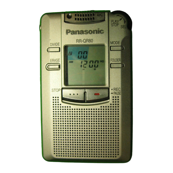
- Page 1 AD9909210C5 IC Recorder RR-QR80 Colour (S)....Silver Type Areas (P)....U.S.A. (PC)....Canada. (E)....Europe, Asia, Latin America, Middle East and Africa. SPECIFICATIONS Specification...
- Page 2 _without batteries; About 47 g (1.7 oz.) Battery life: When used at 25°C(77°F) and on a flat and stable surface] _Batteries; Panasonic alkaline batteries _Playback; About 15 hours _Recording; About 30 hours The battery life may be less depending on the operating conditions.
- Page 3 2. Operation Check Mode This unit is equipped with the functions to check it to record or playback usually and the display of LCD. - Caution! When the checking operation is performed, all recorded data will be cleared. Note: When there are no available items of any track, the unit can not be operated to check it to record and playback.
- Page 4 3. While hold down the STOP switch and press the MODE switch at short time. 4. Release the STOP switch. Note: The item 2 to 4 shown above should be operated within a second. 5. After all segment of LCD lights up, the unit is entered to Operation Check Mode.
- Page 5 4. Press the MODE switch. 5. Check the display of LCD is displayed as shown below. Fig.2-3. Fig.2-3. 6. Press the FOLDER switch. 7. Check the display of LCD is displayed as shown below. Fig.2-4. Fig.2-4.
- Page 6 8. Press the REC switch and record a voice. Fig.2-5. Fig.2-5. 9. Press the STOP switch. 10. The display of LCD as shown below is 10 seconds the recording. Fig.2-6. Fig.2-6.
- Page 7 11. Press the ERACE switch to playback. 12. In playback, check the display of LCD is displayed as shown below. (The display of LCD is difference from the shown below by the time of recording.) Fig.2-7. 13. In playback, check the unit to be fast playback operation when the DIVIDE switch is pressed.
-
Page 8: Operation Checks And Component Replacement / Procedures
15. Pressing the PLAY/STOP and select dial continuously. The format is started. Note: The format is started once, all recorded data in the Flash Memory will be cleared. Fig.2-9. Fig.2-9. 16. Operation Check Mode is canceled when the battery cover is opened. - Page 11 4. Type Illustration of ICs, Transistors and Diodes 5. Schematic Diagram 5.1. Schematic Diagram Notes - This schematic diagram may be modified at any time with the development of new technology. Notes:...
- Page 12 Divide switch (DIVIDE) Erase switch (ERASE) Play/stop select dial switch / (PLAY/STOP, SEL) Recording, pause switch / ( REC, PAUSE) Hold switch (HOLD) Battery cover close detection switch Folder switch (FOLDER) Mode switch (MODE) S11: Stop switch (STOP) VR1: Volume control VR (VOL) - Indicated voltage values are the standard values for the unit measured by the DC electronic circuit tester (high-impedance) with the chassis taken as standard.
- Page 13 Components identified by mark have special characteristics important for safety. Furthermore, special parts which have purposes of fire-retardant (resistors), high-quality sound (capacitors), low-noise (resistors), etc. are used. When replacing any of components, be sure to use only manufacturers specified parts shown in the parts list. - Caution! IC and LSI are sensitive to static electricity.
- Page 14 Function Terminal Name COM3 LCD segment signal output COM2 LCD segment signal output COM1 LCD segment signal output COM0 LCD segment signal output VLC3 LCD reference voltage input terminal (Connected to DGND) VLC2 LCD reference voltage input terminal (1.1 V) VLC1 LCD reference voltage input terminal (2.2 V)
- Page 15 Function Terminal Name Memory chip enable signal output Memory command and data latch signal output 31 PWB Not used, open /RST Reset signal input CODEC (IC2) reset signal output CODEC (IC2) command/data select signal output Beep signal output CODEC (IC2) clock signal output Memory command/data select signal output 38 IREQ0...
- Page 16 Function Terminal Name LED drive signal (L: REC) Recording signal output (L: REC) Fast clock oscillator control signal output Microphone sensitivity setting signal output (H: High, L: Low) Not used, open Not used, open Not used, open I/O Data command bus I/O Data command bus I/O Data command bus I/O Data command bus...
-
Page 17: Replacement Parts List
9. Replacement Parts List Notes: - Important safety notice: Components identified by mark have special characteristics important for safety. Furthermore, special parts which have purposes of fire-retardant (resistors), high-quality sound (capacitors), low-noise (resistors), etc. are used. When replacing any of components, be sure to use only manufactures specified parts shown in the parts list. - Page 18 Remarks Ref. No. Part No. Part Name & Description RYK0971B-S FRONT CABINET UNIT RGV0231-H KNOB,HOLD RHQ0051-K SCREW RKW0592-Q PANEL RYK0973B-H REAR CABINET UNIT XTNR2+5CFN SCREW RFKDNS300R-S JOG SW ASS´Y(SW3) RGW0321-S KNOB,JOG RHQ0060-N SCREW RJC40017 BATT.TERMINAL + RJC80019 BATT.TERMINAL - RMG0529-W ZEBRA GUM RMN0557 HOLDER...
- Page 19 Remarks Ref. No. Part No. Part Name & Description C25,26 RCST0GC227RE 4V 220U ECUZNC104ZFV 16V 0.1U ECST0GY226RR 4V 22U ECUZNC104ZFV 16V 0.1U ECUV1H220JCV 50V 22P ECUV1H120JCV 50V 12P ECUZNC104ZFV 16V 0.1U RCST0GD477RE 4V 470U ECUZNC104ZFV 16V 0.1U ECUVNH103KBV 50V 0.01U ECUVNA105ZFV 10V 1U C37,38...
- Page 20 Remarks Ref. No. Part No. Part Name & Description RL09U028T-T COIL L2,L3 RLQPR22KT2-Y COIL RPN1246 TRAY RPN1247 COVER RPQ1007 SHEET RPK1310 GIFT BOX (PC) RPF0208 SHEET (PC) RPF0208 SHEET RPK1299 GIFT BOX PCB1 REP2896B-M MAIN PCB (RTL) DTC144TUA106 TRANSISTOR 2SK1958T1 TRANSISTOR UN521NTX TRANSISTOR...
- Page 21 Remarks Ref. No. Part No. Part Name & Description R42,43 ERJ3GEYJ104Z 1/16W 100K ERJ3GEYJ102Z 1/16W 1K ERJ3RED105V 1/16W 1M ERJ3RED434V 1/16W 430K ERJ3GEYJ105V 1/16W 1M ERJ3GEYJ102Z 1/16W 1K ERJ3GEYJ100V 1/16W 10 ERJ3GEYJ103Z 1/16W 10K ERJ3GEYJ154V 1/16W 150K R55-58 ERJ3GEYJ153V 1/16W 15K ERJ3GEYJ334V 1/16W 330K ERJ3GEYJ473V...
- Page 22 TC7WH157FUTL XC61AN1802MR MN101C16ACB3 NJM2107FTE1 HN29W6411TT ML2301GA TC7W74FUT2L XC61AN2002MR XC6368B101MR TC7WU04FUT2L .......
- Page 23 SC,/WE TC7W157FUTL HN29W6411TT Notes IC10,11 XC61AN1802MR SWITCHING Signal line : Source signal(analog) 64M bit MEMORY IC12 /CDE,/RES, Signal line : Source signal(digital) R/B,/CE,/OE RESET IO0~7 PO1,O2, IRQ4 O4,05,31, NJM2107FTE1 D0~7 D0~7 IC13 L IN PA4~7, MIC AMP EMP,MID,FUL, KEY SW PO3,P11, /WR,/RD,/CS, MSM7702-02MS...
- Page 24 VOLUME (SIDE : A) (MIC) IC14 IC13 HOLD ELECTRICAL PARTS LOCATION Ref. No. Lo. No. Ref. No. Lo. No. IC13 IC14 Tow R03/LR03, AAA,UM-4 BATTERIES 3V (BATT. COVER CLOSE DET.) SPEAKER 2.8cm(1 "), 8 (REP2896B-M)
- Page 25 (SIDE : B) D1(REC) (PLAY/STOP/SEL) EARPHONE LCD1 MODE DIVIDE ERASE FOLDER STOP REC/ PAUSE IC12 ELECTRICAL PARTS LOCATION Ref. No. Lo. No. Ref. No. Lo. No. IC10 IC11 IC12 IC10 IC11 LCD1...
- Page 26 :POSITIVE VOLTAGE LINE :SOURCE SIGNAL(ANALOG) LINE 2SB1295 6 TB POWER SUPPLY MA735TX MA735TX 3.3V 3.3V TOW R03/LR03, AAA,UM 4 2.7V BATTERIES 3V 2SK1958T1 POWER SUPPLY CONTROL 1.2V 3.3V 3.3V 0.6V XC6368B101MR DC-DC CONVERTER CL170HRCDT (REC) 1.5K 3.3V 0.3V 3300P 2SD1119RTX SWITCHING 1000P SPEAKER...
- Page 27 :POSITIVE VOLTAGE LINE :SOURCE SIGNAL(ANALOG) LINE :SOURCE SIGNAL(DIGITAL) LINE 3.3V TC7W74FUT2L TC7WU04FUT2L (8.19MHz) D TYPE TC7WH157FUTL TRIPLE INVERTER FLIP FLOP SWITCHING 1.7V 3.3V 1.6V 3.3V 1.7V 3.3V REC/PLAY REC/PLAY 1.6V 3.3V 1.2V 1.7V G H I J K L M N 1.6V 3.3V 3.3V...
- Page 28 :POSITIVE VOLTAGE LINE :SOURCE SIGNAL(DIGITAL) LINE 3.3V LCD1(RSL5243-T) LCD DISPLAY 5 6 7 8 9 10 11 12 13 14 15 16 17 18 19 20 21 22 23 24 A B C D E F G H I J K L M N O P Q R S T U V W X 100K 1.6V COM3...