Siemens SIMOTION Equipment Manual
Hide thumbs
Also See for SIMOTION:
- Function manual (186 pages) ,
- Operating instructions manual (184 pages) ,
- Planning manual (66 pages)
Table of Contents
Advertisement
Quick Links
SIMOTION
SIMOTION D410-2
Equipment Manual
Valid for
SIMOTION D410-2 DP and D410-2 DP/PN
as of version 5.4
07/2021
A5E33446720B
Preface
Safety instructions
Description
Operator control (hardware)
Interfaces
Technical data
Dimension drawings
Spare parts / accessories
Standards and approvals
ESD guidelines
1
2
3
4
5
6
7
A
B
Advertisement
Table of Contents

Related Manuals for Siemens SIMOTION


Summary of Contents for Siemens SIMOTION
- Page 1 Preface Safety instructions Description SIMOTION Operator control (hardware) SIMOTION D410-2 Interfaces Technical data Equipment Manual Dimension drawings Spare parts / accessories Standards and approvals ESD guidelines Valid for SIMOTION D410-2 DP and D410-2 DP/PN as of version 5.4 07/2021 A5E33446720B...
- Page 2 Note the following: WARNING Siemens products may only be used for the applications described in the catalog and in the relevant technical documentation. If products and components from other manufacturers are used, these must be recommended or approved by Siemens. Proper transport, storage, installation, assembly, commissioning, operation and maintenance are required to ensure that the products operate safely and without any problems.
-
Page 3: Preface
The SIMOTION D410-2 Manual describes the SIMOTION D410‑2 DP and SIMOTION D410‑2 DP/PN control units. Note A separate SIMOTION D410 Manual is available for the SIMOTION D410 DP and SIMOTION D410 PN control units. Standards The SIMOTION system was developed in accordance with ISO 9001 quality guidelines. - Page 4 • SIMOTION Supplementary Documentation Hotline and Internet addresses SIMOTION at a glance We have compiled an overview page from our range of information about SIMOTION with the most important information on frequently asked topics - which can be opened with only one click.
- Page 5 Preface My Documentation Manager Click the following link for information on how to compile documentation individually on the basis of Siemens content and how to adapt it for the purpose of your own machine documentation: https://support.industry.siemens.com/My/ww/en/documentation Training Click the following link for information on SITRAIN - Siemens training courses for automation products, systems and solutions: http://www.siemens.com/sitrain...
- Page 6 (e.g. on mass storage devices, DVD). If this is not possible for technical reasons, Siemens will be happy to send you this OSS source code in exchange for reimbursement of the processing costs. Please contact the address provided at the end of this section.
-
Page 7: Table Of Contents
1.1.6 Danger to life due to software manipulation when using removable storage media..... 16 1.1.7 Residual risks of power drive systems ................. 17 Specific safety information for SIMOTION D410-2 ............... 18 Description............................19 System overview........................ 19 System components......................23 I/O integration ........................28 SIMOTION D410-2 DP representation ................. - Page 8 Table of contents PROFINET IO interface (SIMOTION D410-2 DP/PN only) ............52 Encoder interface (HTL/TTL/SSI)..................54 Digital I/Os / temperature sensor / analog input..............57 4.6.1 Properties .......................... 57 4.6.2 Interface characteristics ..................... 58 4.6.3 Interface assignment ......................58 4.6.4 Use of the interfaces ......................
- Page 9 General rules ........................107 Device-specific information ....................109 ESD guidelines ........................... 111 ESD definition ........................111 Electrostatic charging of individuals ................. 111 Basic measures for protection against discharge of static electricity........112 Index ..............................113 SIMOTION D410-2 Equipment Manual, 07/2021, A5E33446720B...
- Page 10 Table of contents SIMOTION D410-2 Equipment Manual, 07/2021, A5E33446720B...
-
Page 11: Safety Instructions
For missing or incorrectly implemented protective conductor connection for devices with protection class I, high voltages can be present at open, exposed parts, which when touched, can result in death or severe injury. • Ground the device in compliance with the applicable regulations. SIMOTION D410-2 Equipment Manual, 07/2021, A5E33446720B... - Page 12 • Install built-in units in a suitable metal cabinet in such a way that personnel are protected against fire and smoke, or take other appropriate measures to protect personnel. • Ensure that smoke can only escape via controlled and monitored paths. SIMOTION D410-2 Equipment Manual, 07/2021, A5E33446720B...
- Page 13 • If you come closer than around 2 m to such components, switch off any radios or mobile phones. • Use the "SIEMENS Industry Online Support app" only on equipment that has already been switched off. WARNING...
-
Page 14: Malfunctions Of The Machine As A Result Of Incorrect Or Changed Parameter Settings
As a result of incorrect or changed parameterization, machines can malfunction, which in turn can lead to injuries or death. • Protect the parameterization against unauthorized access. • Handle possible malfunctions by taking suitable measures, e.g. emergency stop or emergency off. SIMOTION D410-2 Equipment Manual, 07/2021, A5E33446720B... -
Page 15: Safety Instructions For Electromagnetic Fields (Emf)
ESD surface, conductive ESD foam, ESD packaging, ESD transport container). 1.1.4 Security information Siemens provides products and solutions with industrial security functions that support the secure operation of plants, systems, machines and networks. In order to protect plants, systems, machines and networks against cyber threats, it is necessary to implement –... -
Page 16: Note Regarding The General Data Protection Regulation
Siemens' products and solutions undergo continuous development to make them more secure. Siemens strongly recommends that product updates are applied as soon as they are available and that the latest product versions are used. Use of product versions that are no longer supported, and failure to apply the latest updates may increase customers' exposure to cyber threats. -
Page 17: Residual Risks Of Power Drive Systems
5. Release of environmental pollutants or emissions as a result of improper operation of the system and/or failure to dispose of components safely and correctly For more information about the residual risks of the drive system components, see the relevant sections in the technical user documentation. SIMOTION D410-2 Equipment Manual, 07/2021, A5E33446720B... -
Page 18: Specific Safety Information For Simotion D410-2
Damage to the CompactFlash card from electrical fields or electrostatic discharge The CompactFlash card is an ESD-sensitive component. De-energize the SIMOTION D410‑2 device before inserting or removing the CompactFlash card. The SIMOTION D410‑2 is in a de-energized state when all the LEDs are OFF. Comply with the ESD rules. NOTICE... -
Page 19: Description
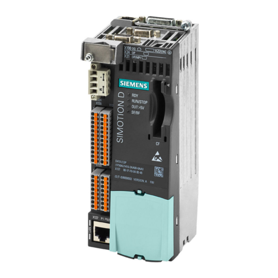
SIMOTION D410-2. Note In order to cover all variants of SIMOTION D in blocksize format, the product will be referred to as "D410-2". Specific product designations will be used for information that applies only to one product version, e.g. D410-2 DP/PN. - Page 20 SIMOTION D410-2 Figure 2-1 SIMOTION D410-2 DP (pictured on left), SIMOTION D410-2 DP/PN (pictured on right) SIMOTION D410-2 is a compact Control Unit for single-axis applications. The Control Unit is snapped directly on to the SINAMICS Power Module in blocksize format and has an integrated drive control for either one servo, one vector or one V/f axis.
- Page 21 Example of a single-axis application Figure 2-2 Application example with one axis ① The example shows a single-axis application, consisting of a SIMOTION D410-2 (Control Unit) ② that is snapped directly on to the SINAMICS Power Module in blocksize format . The motors are supplied with power via the Power Module.
- Page 22 , snapped on to the Power Module in blocksize ③ format The SIMOTION D410-2 DP is snapped directly on to the SINAMICS Power Module. The motors are supplied with power via the Power Module. The encoder is connected by means of DRIVE- CLiQ.
-
Page 23: System Components
2.2 System components Extension of the drive computing performance To fully utilize the motion control performance of a SIMOTION D410-2 when required, the drive- side computing performance can be extended by connecting additional SINAMICS S/G Control Units (e.g. CU305, CU310‑2, CU320‑2, CU250S‑2, etc.) via PROFIBUS or PROFINET to the SIMOTION D410‑2. - Page 24 The measuring sockets can output any analog signals. The DRIVE-CLiQ interface permits a fast connection to the SINAMICS drive components. System software The basic functionality of SIMOTION D410‑2 is supplied separately on a Com‐ pactFlash Card containing the following: • SIMOTION runtime (kernel) •...
- Page 25 Can also be operated as an isochronous slave on the PROFIBUS DP. Teleservice adapter Remote diagnostics PROFINET IO The SIMOTION D410‑2 DP/PN can communicate with the following components via the onboard PROFINET IO interface. Table 2-3 Components on the PROFINET IO...
- Page 26 Table 2-4 Components on the Ethernet Component Function Programming device (PG/PC) … configures, assigns parameters, programs, and tests using the SIMOTION SCOUT Engi‐ neering System (ES). Master computer … communicates with other devices via UDP, TCP/IP. SIMATIC HMI device ... is used for operating and monitoring functions. This is not an essential requirement for the operation of the SIMOTION D410‑2.
- Page 27 … enables the number of DRIVE-CLiQ interfaces to be increased and the creation of a point-to- DRIVE-CLiQ hub point topology. Note Please note that SIMOTION D410‑2 components in booksize format (Controller Extension, Motor Modules, Line Modules, etc.) are not supported. SIMOTION D410‑2 can only be used with the following Power Modules: • PM340 •...
-
Page 28: I/O Integration
I/O integration Note Note that not all modules in the ET 200 I/O family are approved for SIMOTION. Moreover, system- related functional differences can come into play when these I/Os or I/O systems are used on SIMOTION vs. on SIMATIC. For example, special process-control functions (e.g. HART modules, etc.) are not supported by SIMOTION for the ET 200M distributed I/O system. -
Page 29: Simotion D410-2 Dp Representation
The following figure shows a SIMOTION D410-2 DP with the interfaces and front elements. Figure 2-4 Location of interfaces and front elements for SIMOTION D410-2 DP The interface to the power module (PM) is located at the rear of the SIMOTION D410-2. SIMOTION D410-2 Equipment Manual, 07/2021, A5E33446720B... - Page 30 Description 2.4 SIMOTION D410-2 DP representation Figure 2-5 Power Module Interface (PM-IF) See also Interfaces (Page 47) SIMOTION D410-2 Equipment Manual, 07/2021, A5E33446720B...
-
Page 31: Simotion D410-2 Dp/Pn Drawing
The following figure shows a SIMOTION D410-2 DP/PN with the interfaces and front elements. Figure 2-6 Location of interfaces and front elements for SIMOTION D410-2 DP/PN The interface to the power module (PM) is located at the rear of the SIMOTION D410-2. SIMOTION D410-2 Equipment Manual, 07/2021, A5E33446720B... -
Page 32: Type Plates
The following figure shows all the information that the rating plate on the module rear contains. Figure 2-8 Rating plate using the SIMOTION D410-2 DP/PN as an example Note The information contained in each field of the rating plate on your actual Control Unit may differ from that presented in this manual (for example, a later product version, approvals and marks that have not yet been earned, etc. -
Page 33: Compactflash Card
CompactFlash card Properties The CF card is mandatory for operation of the SIMOTION D410‑2. The CF card must be ordered as a separate component; it is not included in the SIMOTION D410‑2 scope of delivery. The SIMOTION Kernel (SIMOTION D410-2 firmware) and the software used to control the drives (SINAMICS firmware) are contained on the CF card. - Page 34 Description 2.7 CompactFlash card The CF card is supplied in a bootable format with the latest SIMOTION Kernel and drive software. CF card Different CF cards are available for SIMOTION D410‑2. • 2 GB CF, article number 6AU1400-1QA20-0AA0 • 1 GB CF, article number 6AU1400-1PA23-0AA0 •...
- Page 35 Path interpolation is supported as of V4.4. SINAMICS licenses Selected SINAMICS licenses can be used with a SIMOTION D CF card. Only one relicensing is possible. A prelicensing of SIMOTION D CF cards via Z options is not possible with SINAMICS licenses.
-
Page 36: Data Matrix Code
With SINAMICS licenses, underlicensing of SINAMICS Integrated is indicated by the flashing SF LED on the SIMOTION D Control Unit. An entry is also made in the diagnostic buffer and the underlicensing is displayed in the License dialog box of SIMOTION SCOUT. The licensing is performed (as for SIMOTION licenses) via SIMOTION SCOUT or via the SIMOTION license key on the CF card. -
Page 37: Licensing
POS license, it is better to use the D410‑2 MultiAxes Package. Note If you use more than one real axis with SIMOTION D410-2, you must license these additional axes. The axis license with the highest functionality is covered by the inclusive license (a real axis). - Page 38 Description 2.9 Licensing Additional references For more information about license management, see the SIMOTION SCOUT Configuration Manual. General information on the subject of licensing can be found in the SIMOTION PM 21 Catalog. SIMOTION D410-2 Equipment Manual, 07/2021, A5E33446720B...
-
Page 39: Operator Control (Hardware)
The following figure shows the arrangement of the operator control and display elements on the SIMOTION D410-2. Figure 3-1 Operator control and display elements: SIMOTION D410-2 DP (on the left), SIMOTION D410-2 DP/PN (on the right) SIMOTION D410-2 Equipment Manual, 07/2021, A5E33446720B... -
Page 40: Operator Controls
3.2 Operator controls Operator controls 3.2.1 Service selector switch Layout SIMOTION D410-2 provides a service selector switch (SVC) behind the blanking cover in the lower area of the front panel. Figure 3-2 Service selector switch, switch position "0" NOTICE Damage from electrostatic discharge The rotary switch can be destroyed by static electricity. -
Page 41: Mode Selector Switch
DIAG button. See Section DIAG button (Page 43). 3.2.2 Mode selector switch Layout SIMOTION D410-2 provides a mode switch (PLC) behind the blanking cover in the lower area of the front panel. Figure 3-3 Mode switch, switch position "0" NOTICE Damage from electrostatic discharge The rotary switch can be destroyed by static electricity. - Page 42 Hardware Installation Manual. Note In the "RUN" setting, you can also control the SIMOTION D410-2 operating mode from the SIMOTION SCOUT engineering system. This means that it is not necessary to adjust the mode switch to change the operating mode.
-
Page 43: Diag Button
Instructions. 3.2.3 DIAG button Layout The DIAG button is located on the SIMOTION D410‑2 behind the blanking cover on the front. Figure 3-4 DIAG button Function The diagnostic data and non-volatile SIMOTION data is backed up on the CompactFlash card via the DIAG button. -
Page 44: Reset Button
The entire system is reset when the RESET button is pressed and a new power-up of the system forced. 3.2.5 Switch S5.0 Layout SIMOTION D410-2 provides the S5.0 switch behind the blanking cover in the lower area of the front panel. Figure 3-6 Switch S5.0 Function The DIP switch is used for switching the analog input (X131 connector) as voltage or current input. -
Page 45: Simotion Compactflash Card
(Page 39)). NOTICE Impermissible use of the CompactFlash card The CF card of the SIMOTION D410-2 must not be used in a SIMOTION D410, D4x5 or D4x5-2! NOTICE Elektrostatisch gefährdete Bauelemente The CompactFlash card is an ESD-sensitive component. -
Page 46: Error And Status Displays
Group error / bus fault Additional information You can perform a detailed diagnosis with a PG/PC and the engineering system. For information about diagnostics using LED displays, refer to the SIMOTION D410-2 Commissioning and Hardware Installation Manual, Section "Diagnostics using LED displays". SIMOTION D410-2... -
Page 47: Interfaces
Overview of interfaces This section describes the interfaces of the SIMOTION D410‑2. Information on the arrangement of the interfaces on the module can be found in Sections SIMOTION D410-2 DP representation (Page 29) and SIMOTION D410-2 DP/PN drawing (Page 31). -
Page 48: Drive-Cliq Interface
Reserved, do not use Receive data - Reserved, do not use Reserved, do not use + (24 V) Power supply M (0 V) Electronic ground Signal type: I = Input; O = Output; VO = Voltage Output SIMOTION D410-2 Equipment Manual, 07/2021, A5E33446720B... - Page 49 Interfaces 4.2 DRIVE-CLiQ interface Connectable devices The following table contains the components that can communicate with SIMOTION D410-2 via the DRIVE-CLiQ interface. Note the max. number of nodes that can be connected to the DRIVE- CLiQ! Note Note also the topology rules of the SINAMICS S120, see SINAMICS S120 Function Manual, Chapter "Rules for wiring with DRIVE-CLiQ".
-
Page 50: Profibus Dp Interfaces
• TM15/TM17 High Feature SIMOTION Terminal Modules Commissioning Manual • SIMOTION Terminal Modules TM15 / TM17 Manual PROFIBUS DP interfaces Properties SIMOTION D410-2 provides the following interfaces for connection on the PROFIBUS DP: Table 4-6 SIMOTION D410-2 PROFIBUS interfaces D410-2 DP... - Page 51 The 1P5 voltage is provided exclusively for the bus terminal. No OLPs are permitted. Signal type: VO = Voltage output (power supply); O = Output; B = Bidirectional X24 interface assignment Table 4-9 PROFIBUS DP interface X24 (SIMOTION D410‑2 DP only) Representation Signal name Signal Meaning...
-
Page 52: Profinet Io Interface (Simotion D410-2 Dp/Pn Only)
PROFINET is an open component-based industrial communication system using Ethernet for distributed automation systems. SIMOTION D410‑2 DP/PN has a PROFINET interface with two ports (X150 P1-P2) onboard. The PROFINET interface supports operation of a SIMOTION D410‑2 DP/PN as an IO controller and/or as an I device. - Page 53 Interfaces 4.4 PROFINET IO interface (SIMOTION D410-2 DP/PN only) Interface assignment Table 4-11 Assignment of the ports X150 P1 to P2 Representation Name Description Send data + Send data - Receive data + Reserved, do not use Reserved, do not use...
-
Page 54: Encoder Interface (Htl/Ttl/Ssi)
• Distributed I/O • Drive units with PROFINET IO interface (standard devices) The SIMOTION D410‑2 DP/PN then assumes the role of a PROFINET IO controller and can offer the following functions: • PROFINET IO controller, I-device (also controller and device simultaneously) •... - Page 55 For Pin 6 / Pin 9: At an encoder supply of 5 V, the voltage drops on the encoder supply cables are recorded and compensated by means of the sense cables. For this purpose, the sensor supply is corrected on the SIMOTION D410-2. SIMOTION D410-2...
- Page 56 See SINAMICS S120/S150 List Manual for setting the threshold. Note We recommend that bipolar encoders are used When using unipolar encoders, the unused negative track signals can either be connected or connected to ground. This results in different switching thresholds. SIMOTION D410-2 Equipment Manual, 07/2021, A5E33446720B...
-
Page 57: Digital I/Os / Temperature Sensor / Analog Input
Digital I/Os / temperature sensor / analog input 4.6.1 Properties The onboard I/Os (Onboard I/Os) of the SIMOTION D410-2 are assigned to the SINAMICS Integrated. An appropriate configuration allows the I/Os also to be used by SIMOTION. Digital I/Os The digital I/Os at the X120, X121 and X130, X131 connectors are provided for the connection of sensors and actuators. -
Page 58: Interface Characteristics
To prevent an incorrect connection, the X120, X121, X130 and X131 connectors are supplied coded. The terminal and pin numbers are also inscribed on the connectors. 4.6.3 Interface assignment The following tables contain the pin assignments of the onboard I/Os. SIMOTION D410-2 Equipment Manual, 07/2021, A5E33446720B... - Page 59 • DO 16+ (or F‑DO 0) Reference potential for DI 17+ / DI 19+ / DI 21+ (or F-DI 0 to F-DI 2; second shutdown path) Functionality depends on the parameterized Safety Integrated functions. SIMOTION D410-2 Equipment Manual, 07/2021, A5E33446720B...
- Page 60 Power Module Chassis: X41.1 and X41.2 on the Control Interface Module (CIM) Extended Functions Control takes place via the 2-channel F-DI of the SIMOTION D410‑2: F‑DI 0 … F‑DI 2 (X120.3...11) A fail-safe digital input is made up of two digital inputs.
- Page 61 61800-5-1 may be connected to terminals "+Temp" and "-Temp". Use a Sensor Module External (SME120 or SME125) or Terminal Module TM120 if safe electrical separation cannot be guaranteed (for linear motors or third-party motors, for example). SIMOTION D410-2 Equipment Manual, 07/2021, A5E33446720B...
- Page 62 The use of the digital inputs (DI 0 ... DI 3) requires terminal M2 be connected. This is achieved • Providing the reference ground of the digital inputs, or • a jumper to terminal M. This removes the electrical isolation for these digital inputs. SIMOTION D410-2 Equipment Manual, 07/2021, A5E33446720B...
- Page 63 The possible cause may be missing power supply (X130.6) or a short-circuit. For further details, see the SINAMICS S120/S150 List Manual, Section List of faults and alarms. Note If the 24 V supply is briefly interrupted, the digital output is deactivated until the interruption has been rectified. SIMOTION D410-2 Equipment Manual, 07/2021, A5E33446720B...
- Page 64 For further details, see the SINAMICS S120/S150 List Manual, Section List of faults and alarms. See also SIMOTION D410-2 DP connection examples (Page 68) SIMOTION D410-2 DP/PN connection examples (Page 72) SIMOTION D410-2 Equipment Manual, 07/2021, A5E33446720B...
-
Page 65: Use Of The Interfaces
Use of the interfaces Fail-safe digital I/Os (F-DI/F-DO) The SIMOTION D410-2 provides three fail-safe isolated digital inputs (F-DI) and one fail-safe isolated digital output (F-DO): • An F-DI consists of a digital input and a second digital input to which the cathode of the optocoupler is connected. - Page 66 With a signal edge at the relevant input, the current actual values of one or more encoders are measured with positioning accuracy to determine lengths and distances. The assignment of the inputs is not fixed, and the special use is activated in the SIMOTION SCOUT engineering system. Note An additional external electronics power supply via terminal X124 is required in two cases: •...
- Page 67 Additional references For information on configuring the digital I/Os as freely addressable I/Os, inputs of measuring inputs or outputs of output cams, see the SIMOTION D410-2 Commissioning and Hardware Installation Manual. For information on the configuration and function of the measuring input and output cam technology objects, refer to the SIMOTION Output Cams and Measuring Inputs Function Manual.
-
Page 68: Simotion D410-2 Dp Connection Examples
Interfaces 4.6 Digital I/Os / temperature sensor / analog input 4.6.5 SIMOTION D410-2 DP connection examples Connection examples without Safety Integrated functions Figure 4-2 Example of circuits for the DI/DO without Safety Integrated functions SIMOTION D410-2 Equipment Manual, 07/2021, A5E33446720B... - Page 69 Interfaces 4.6 Digital I/Os / temperature sensor / analog input Figure 4-3 Connection example of SIMOTION D410-2 DP without Safety Integrated functions SIMOTION D410-2 Equipment Manual, 07/2021, A5E33446720B...
- Page 70 Interfaces 4.6 Digital I/Os / temperature sensor / analog input Connection examples with Safety Integrated Extended and Advanced Functions Figure 4-4 Connection example of SIMOTION D410-2 DP with Safety Integrated Extended and Advanced Functions SIMOTION D410-2 Equipment Manual, 07/2021, A5E33446720B...
- Page 71 Interfaces 4.6 Digital I/Os / temperature sensor / analog input 24 V1 Figure 4-5 Example of circuits for the F-DI and F-DO with Safety Integrated Extended and Advanced Functions SIMOTION D410-2 Equipment Manual, 07/2021, A5E33446720B...
-
Page 72: Simotion D410-2 Dp/Pn Connection Examples
Interfaces 4.6 Digital I/Os / temperature sensor / analog input 4.6.6 SIMOTION D410-2 DP/PN connection examples Connection examples without Safety Integrated Extended and Advanced Functions Figure 4-6 Example of circuits for the DI/DO without Safety Integrated Extended and Advanced Functions... - Page 73 Interfaces 4.6 Digital I/Os / temperature sensor / analog input Figure 4-7 Connection example of SIMOTION D410-2 DP/PN without Safety Integrated Extended and Advanced Functions SIMOTION D410-2 Equipment Manual, 07/2021, A5E33446720B...
- Page 74 Interfaces 4.6 Digital I/Os / temperature sensor / analog input Connection examples with Safety Integrated Extended and Advanced Functions Figure 4-8 Connection example of SIMOTION D410-2 DP/PN with Safety Integrated Extended and Advanced Functions SIMOTION D410-2 Equipment Manual, 07/2021, A5E33446720B...
-
Page 75: Power Supply
Power supply The X124 interface is provided for connection of the external power supply. Note When using external power supplies (e.g. SITOP), the ground potential must be connected with the protective ground terminal (PELV). SIMOTION D410-2 Equipment Manual, 07/2021, A5E33446720B... - Page 76 Screwdriver 0.5 x 3 mm (M2.5) Tightening torque 0.4 to 0.5 Nm (3.5 ... 4.4 lbf in) Max. current carrying capacity, incl. loop-through 20 A (15 A per UL/CSA) Max. cable length 10 m SIMOTION D410-2 Equipment Manual, 07/2021, A5E33446720B...
-
Page 77: Ethernet Interface
Disconnection of 24 V plug-in connections is only permitted when the power is off. Ethernet interface Properties SIMOTION D410-2 has an X127 interface for connection to Industrial Ethernet. Industrial Ethernet is a communication network with a transmission rate of 10/100 Mbit/s. SIMOTION D410-2 Equipment Manual, 07/2021, A5E33446720B... - Page 78 • Connection of HMI systems • Communication with other devices over TCP/IP or UDP communication • IT communication (e.g. via SIMOTION IT OPC XML‑DA) For further information on the software packages, see the SIMOTION PM 21 Catalog. Interface characteristics Table 4-25...
-
Page 79: Measuring Sockets
Load current max. 3 mA Sustained short-circuit proof Reference potential is M terminal Interface assignment Table 4-28 Interface assignments T0, T1 and T2 Representation Designation Measuring socket 0 Measuring socket 1 Measuring socket 2 Ground SIMOTION D410-2 Equipment Manual, 07/2021, A5E33446720B... -
Page 80: Power Module Interface
4.10 Power Module Interface SIMOTION D410-2 can be connected to a SINAMICS Power Module in blocksize format via the Power Module interface. Power Modules PM340 and PM240‑2 (PM240‑2 as of SIMOTION V4.4/SINAMICS V4.7) can be used. -
Page 81: Technical Data
60721‑3‑1:1997 Ambient conditions Conditions of use SIMOTION D410-2 meets the conditions of use for Class 3C3 according to DIN EN 60721‑3‑3:1995 (operating locations with high traffic densities and in the immediate vicinity of industrial equipment with chemical emissions). Protect the device from environmental effects SIMOTION D410-2 is designed for use in stationary, weather-protected locations. - Page 82 • Installations requiring special monitoring such as: – Elevator installations – Electrical systems in particularly hazardous rooms An additional measure for using SIMOTION D410-2 can, for example, be installation in cabinets. Note The components must be protected against conductive contamination, e.g. by installing them in a control cabinet with degree of protection IP54 according to IEC 60529 or NEMA 12.
- Page 83 SINAMICS S120 for AC Drives Manual. Vibration reduction If SIMOTION D410-2 is subjected to larger shocks or vibrations, you must use suitable measures to reduce the acceleration or the amplitude. We recommend installation on shock-absorbing material (e.g. rubber-metal vibration dampers).
-
Page 84: System Data, Connection Values, Dimensions And Weight
Technical data 5.3 System data, connection values, dimensions and weight System data, connection values, dimensions and weight General technical data The SIMOTION D410‑2 has an integrated fan. Table 5-3 General technical data Dimensions and weight Dimensions W x H x D D410-2 DP 73 x 186.8 x 74.4 mm... -
Page 85: Interfaces And Performance Features
Interfaces and performance features 5.4.1 PLC and motion control performance Number of axes and clock cycles Table 5-7 Maximum number of axes and minimum cycles for SIMOTION D410-2 PLC and motion control performance Maximum number of axes 8 axes Minimum PROFIBUS cycle clock 0.5 ms PROFIBUS Integrated... -
Page 86: Communication
Physical I/O address space for each interface, one each for inputs and outputs PROFIBUS Integrated 4 KB PROFIBUS 1 KB PROFINET (D410‑2 DP/PN only) 6 KB (as of V4.5) 4 KB (up to V4.4) SIMOTION D410-2 Equipment Manual, 07/2021, A5E33446720B... -
Page 87: Onboard I/Os
Current consumption typical at 1 signal level 3.5 mA at 24 V 5 mA at 24 V Input delay, typical (hardware) • Signal "0" → "1" • 50 μs • Signal "1" → "0" • 150 μs SIMOTION D410-2 Equipment Manual, 07/2021, A5E33446720B... - Page 88 150 μs / 400 μs • Signal "0" → "1" • 75 μs / 100 μs • Signal "1" → "0" Output cam output, resolution Typ. 125 µs Output cam output, reproducibility Typ. 125 µs SIMOTION D410-2 Equipment Manual, 07/2021, A5E33446720B...
- Page 89 "not actively" forced to LOW (example: Output of a TM17 module: Falling edge). Recommendation: Where the connected components do not have special output drivers, the recommendation is to use the rising edges for measurements. SIMOTION D410-2 Equipment Manual, 07/2021, A5E33446720B...
- Page 90 = 24 V; load 48 Ω; high ("1") = 90% V ; low ("0") = 10% V Analog input Table 5-16 Technical data for the analog input Number of inputs Galvanic isolation Common-mode range -12 … +12 V SIMOTION D410-2 Equipment Manual, 07/2021, A5E33446720B...
-
Page 91: Onboard Encoder Interface
TTL or HTL incremental encoders (with adjustable param‐ eters) • Absolute encoder Power supply 24 VDC / 0.35 A or 5 VDC / 0.35 A Short-circuit and overload proof Limit frequency 500 kHz SSI baud rate 100 ... 1000 kBaud SIMOTION D410-2 Equipment Manual, 07/2021, A5E33446720B... - Page 92 The CUA32 control unit adapter also provides an encoder interface for an HTL, TTL or SSI encoder. The technical data of the CUA32 adapter module can be found in the SINAMICS S120 AC Drive Manual. SIMOTION D410-2 Equipment Manual, 07/2021, A5E33446720B...
-
Page 93: Clock
(excluding software clock). The buffer is recharged in the POWER ON state. If the real-time clock backup time is exceeded, the time is reset. If the SIMOTION D410-2 is reset to its factory settings, the clock is also reset to the "default setting when delivered". - Page 94 Technical data 5.6 Certificates, approvals, declarations of conformity SIMOTION D410-2 Equipment Manual, 07/2021, A5E33446720B...
-
Page 95: Dimension Drawings
Dimension drawings SIMOTION D410-2 DP dimension drawing Figure 6-1 SIMOTION D410-2 DP dimension drawing (dimensions in mm) SIMOTION D410-2 Equipment Manual, 07/2021, A5E33446720B... -
Page 96: Simotion D410-2 Dp/Pn Dimension Drawing
Insufficient ventilation clearances result in overheating and therefore in more failures and a shortened service life of the component. Maintain 50 mm ventilation clearances above and below the component. SIMOTION D410-2 DP/PN dimension drawing Figure 6-2 SIMOTION D410-2 DP/PN dimension drawing (dimensions in mm) SIMOTION D410-2 Equipment Manual, 07/2021, A5E33446720B... -
Page 97: Mounting Plate Dimension Drawing
Insufficient ventilation clearances result in overheating and therefore in more failures and a shortened service life of the component. Maintain 50 mm ventilation clearances above and below the component. Mounting plate dimension drawing Figure 6-3 Mounting plate dimension drawing (dimensions in mm) SIMOTION D410-2 Equipment Manual, 07/2021, A5E33446720B... -
Page 98: Cad Data, Dimension Drawings, And Circuit-Diagram Macros
(https://support.industry.siemens.com/my/ww/en/ CAxOnline#CAxOnline). Circuit-diagram macros EPLAN circuit-diagram macros are available for the SIMOTION D410-2. The macros assist you when creating circuit diagrams. The EPLAN circuit diagram macros can be ordered at the following Internet addresses: • Drive Technology Configurator Industry Mall (http://www.siemens.com/dt-configurator) •... -
Page 99: Spare Parts / Accessories
Spare parts / accessories Available spare parts and accessories Table 7-1 Spare parts and accessories Parts for SIMOTION D410-2 Article number Accessories Spare part 2 GB CompactFlash card (CF card) 6AU1400-1QA20-0AA0 (latest CF card at the time of publication of this documentation) -
Page 100: Tm31 Terminal Module
You can find order data information for other SINAMICS drive components, such as Line Modules, Motor Modules, DRIVE-CLiQ cables, etc. in Catalog SIMOTION PM 21. Note The procedure for replacing the SIMOTION D410‑2 fan is described in the SIMOTION D410‑2 Commissioning and Hardware Installation Manual. Spares On Web Spares On Web is an information system that enables you to find out which spare parts are available for your device. -
Page 101: Tm41 Terminal Module
Insufficient ventilation clearances result in overheating and therefore in more failures and a shortened life of the component. Maintain 50 mm ventilation clearances above and below the component. Additional references For further information on the TM31 Terminal Module, see the SIMOTION D410-2 Commissioning and Hardware Installation Manual. TM41 terminal module Characteristics The TM41 Terminal Module can be used to expand the number of digital I/Os and analog inputs within a drive system. -
Page 102: Tm54F Terminal Module
The TM54F offers safe digital inputs and outputs for control of Safety Integrated functions of SINAMICS. A SIMOTION D410‑2 can be assigned exactly one TM54F which is connected via DRIVE-CLiQ. The TM54F Terminal Module is an alternative to using Safety Integrated functions via the onboard terminals (F‑DI, F‑DO) or via PROFIsafe. -
Page 103: Tm15 And Tm17 High Feature Terminal Modules
The TM15 and TM17 High Feature Terminal Modules are used to implement inputs of measuring inputs and outputs of output cams for SIMOTION D. In addition, these Terminal Modules provide drive-related digital I/Os with short signal delay times. TM15 and TM17 High Feature are connected by means of DRIVE-CLiQ. -
Page 104: Cua31/Cua32 Control Unit Adapter
Maintain 50 mm ventilation clearances above and below the component. Additional references Detailed information about the TM15 and TM17 High Feature can be found in the SIMOTION Terminal Modules TM15 / TM17 High Feature Commissioning Manual. CUA31/CUA32 control unit adapter... -
Page 105: Dmc20/Dme20 Drive-Cliq Hub
DRIVE-CLiQ link and therefore the data exchange. The DMC20/DME20 is also used with a SIMOTION D410‑2 when a second encoder is required. As an SMx Sensor Module and a motor with DRIVE-CLiQ interface only have one DRIVE-CLiQ interface, a DMC20/DME20 must be used for a second encoder via DRIVE-CLiQ. - Page 106 Spare parts / accessories 7.7 DMC20/DME20 DRIVE-CLiQ hub CUA32 is used, the DMC20/DME20 is not required. Alternatively, a second encoder can also be connected via the X23 interface on the SIMOTION D410‑2. NOTICE Overheating if ventilation clearances are too small Insufficient ventilation clearances result in overheating and therefore in more failures and a shortened life of the component.
-
Page 107: Standards And Approvals
European standards (EN). Electromagnetic compatibility Standards for EMC are satisfied if the EMC Installation Guideline is observed. SIMOTION products are designed for industrial use in accordance with product standard DIN EN 61800‑3, Category C2. cULus approval Listed component mark for United States and the Canada Underwriters Laboratories (UL) according to Standard UL 508, File E164110, File E115352, File E85972. - Page 108 China Compulsory Certification SIMOTON D does not belong to the validity area of the China Compulsory Certification (CCC). China RoHS SIMOTION D complies with the China RoHS directive. You can find more information on the Internet (https://support.industry.siemens.com/cs/ww/en/view/109738656). SIMOTION D410-2 Equipment Manual, 07/2021, A5E33446720B...
-
Page 109: Device-Specific Information
The same installation instructions apply for the SIMOTION D410-2 Control Unit as for the SINAMICS S120 CU310-2 Control Unit with regard to EMC. For further information on this topic also refer to the SIMOTION PM 21 Catalog as well as the SINAMICS Function Manuals. - Page 110 Standards and approvals A.2 Device-specific information SIMOTION D410-2 Equipment Manual, 07/2021, A5E33446720B...
-
Page 111: Esd Guidelines
This figure indicates the maximum electrostatic charges that can accumulate on an operator when he comes into contact with the indicated materials. These values comply with the specifications in IEC 801-2. SIMOTION D410-2 Equipment Manual, 07/2021, A5E33446720B... -
Page 112: Basic Measures For Protection Against Discharge Of Static Electricity
If you have to take measurements on a module, make sure that you first discharge any static that may have accumulated in your body. To do this, touch a grounded metal object. Only use grounded measuring instruments. SIMOTION D410-2 Equipment Manual, 07/2021, A5E33446720B... -
Page 113: Index
Ambient conditions Connection examples, 68 Climatic, 82 Technical data, 87 Mechanical, 82 Dimension drawing, 98 Analog input, 57 Mounting plate, 97 SIMOTION D410-2 DP, 95 SIMOTION D410-2 DP/PN, 96 Dimensions, 84 Display elements, 39 Backup DMC20 Non-volatile data, 84 Characteristics, 105... - Page 114 I/O systems Motion Control, 85 PROFINET, 25, 26 PLC, 85 Interface assignment PLC and motion control X120, 59 SIMOTION D410-2 DP performance, 85 X121, 62 SIMOTION D410-2 DP/PN performance, 85 X130, 63 Possible applications, 22 X131, 64 PROFIBUS DP interface...
- Page 115 Index Communication, 86 Digital inputs/outputs, 87 Encoder interface, 91 Mounting plate, 85 SIMOTION D410-2 memory, 84 Temperature sensor connection, 60 Terminal Module TM15, 103 TM15 DI/DO, 103 TM17 High Feature, 103 TM31, 100 TM41, 101 TM54F, 102 UL certification, 107...
- Page 116 Index SIMOTION D410-2 Equipment Manual, 07/2021, A5E33446720B...