Table of Contents
Advertisement
Quick Links
WASHING MACHINE
SERVICE MANUAL
CAUTION
READ THIS MANUAL CAREFULLY TO DIAGNOSE PROBLEMS
CORRECTLY BEFORE OFFERING SERVICE.
BEFORE SERVICING THE WASHING MACHINE, UNPLUG THE POWER
CORD TO AVOID THE RISK OF AN ELECTRIC SHOCK.
WHEN SERVICING INTERNAL PARTS ,
USE ONLY S
E
R
V
C I
E
P
A
R
T
AFTER SERVICING THE ELECTRIC WIRE, INSURE THAT INSULATION
TAPE IS APPLIED TO PREVENT AN ELECTRICAL SHORT.
MODEL :
F*V5*RP(0~9)
website :
http://biz.lgservice.com
e-mail : http://LGEservice.com/techsup.html
S
SUPPLIED FROM LG.
Advertisement
Table of Contents
Troubleshooting

Related Manuals for LG F V5 RP Series


Summary of Contents for LG F V5 RP Series
- Page 1 BEFORE SERVICING THE WASHING MACHINE, UNPLUG THE POWER CORD TO AVOID THE RISK OF AN ELECTRIC SHOCK. WHEN SERVICING INTERNAL PARTS , USE ONLY S SUPPLIED FROM LG. AFTER SERVICING THE ELECTRIC WIRE, INSURE THAT INSULATION TAPE IS APPLIED TO PREVENT AN ELECTRICAL SHORT. MODEL :...
-
Page 2: Table Of Contents
CONTENTS 1. SPECIFICA TIONS ..........................3 2. FEATURES & TECHNICAL EXPLANATION ..................4 3. PARTS IDENTIF IC ATION ........................6 4. INSTALLATION ............................8 5. OPERATION ............................13 6. WIRING DIAGRAM / PC B LAYOUT ....................20 7. TROUBLESHOOTING ........................... 20 7-1.BEFORE PERFORMING SERVICE .................... -
Page 3: Specifica Tions
1. SPECIFICATION ITEM Refer to 1 page POWER SUPPLY 220 V - 240 V ~,50Hz/60Hz PRODUCT WEIGHT 73kg WASHING 155 W SPIN 490 W ELECTRICITY DRAIN MOTOR 20 W CONSUMPTION WASH HEATER 2200 W DRY HEATER 1350 W WASH 46 rpm REVOLUTION SPIN SPEED... -
Page 4: Features & Technical Explanation
2. FEATURES & TECHNICAL EXPLANATION 2-1. Product Features Inverter Direct Drive system The advanced Brushless DC motor directly drives the drum without belt and pulley. 6 Motion Washer is able to perform various drum actions or a combination of different actions depending on the wash program selected. Combined with a controlled spin speed and the ability of the drum to rotate both left and right, the wash performance of the machine is greatly improved, giving you perfect results every time. - Page 5 2-2. DETERMINE WASHING TIME BY FUZZY LOGIC To get the best washing performance optimal time is determined by sensing the water temperature, selected washing temperature and laundry amount. water temperature washing time the best selected FUZZY washing rinse time washing LOGIC temperature performance...
-
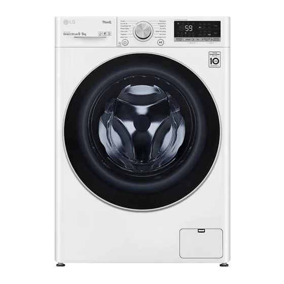
Page 6: Parts Identif Ic Ation
3. PARTS IDENTIFCATION... - Page 7 3. PARTS IDENTIFCATION...
-
Page 8: Installation
4. INSTALLATION INSTALLATION The appliance should be installed as follows. Check the conditions of installation area. 1. Check level ground. horizontal On raised foundations or upper level homes, the can be caused by the type of flooring. vibrations It may be to a different area in the home or have the floor necessary to move machine... - Page 10 Connect Drain Hose. If the drain hose is not installed properly, the unit will not drain properly. This allows water to back flow into the unit which can cause odors. Refer to Owner Manual for proper drain hose installation. The odor could also be coming from the home’s drain to which the drain hose is attached. Laundry tub about 100 cm Hose...
- Page 11 Check the horizontality with a level (Gage). Step 1 If washing machine legs are loose or not Screwed in, then with the spanner wrench. tighten Using the level, level the washing machine from front to back and side to side. A level Higher Tighten...
- Page 12 Test operation Preparation Press the power button. Press the START/PAUSE button. washing. · Connect the power plug to the · In case of Coloreds program. outlet. · Connect the inlet hose. Check the water heating. Check automatic reverse turn. Check the water supply. ·...
-
Page 13: Operation
5. OPERATION How to use washer Control panel SmartDiagnosis function is available only for the products with LED display a SmartDiagnosis mark. Power Button Start/Pause Options Program dial Button Power Program Dial Press the Power button to turn power on Programs are available according to the and off. - Page 14 How to use washer Options Steam: This option is featured with the enhanced washing performance. This option consumes low energy. Rinse + ( Add rinse once. Dealy End : You can set a time delay so that the washing machine will start automatically and finish after a specifed time interval.
- Page 15 How to use washer Temp. Pre Wash By touching the Temp. button the water If the laundry is heavily soiled, “Pre Wash” temperature can be selected. course is effective. - Cold 1. Touch the Power button. - 20°C, 30°C, 40°C, 60°C, 95°C 2.
- Page 16 How to use washer Child Lock Select this function to lock the buttons on the control assembly to prevent tampering. "Child Lock" can be set only during the washing cycle. Locking the control panel 1. Touch and hold the Child Lock button for 3 seconds.
- Page 17 How to use washer Tub Clean Tub Clean is a special cycle to clean the inside of the washing machine. A higher water level is used in this cycle at higher spin speed . Perform this cycle regularly. 1. Remove any clothing or items from the washer and close the door.
-
Page 18: Wiring Diagram/Pcb Layout
WIRING DIAGRAM/PCB LAYOUT... - Page 19 PCB Layout (Main) Dry Heater Heater PCB POWER Door Switch yellow&red:door switch black:door switch orange:door switch Moter Stator Control Drain motor V-U/U-W /W-V BLDC pump →R:8~11Ω white:U black:V yellow:W Water sensor blue&white:thermister blue:common violet:pressure switch orange:pressure switch Display Vibration Sensor DC Valve Dry Fan motor Thermistor...
-
Page 20: Troubleshooting
7. TROUBLESHOOTING 7-1. CHECK BEFORE SERVICE Before servicing ask the customer what the trouble is. Check the adjustments. (Power supply :220-240V~, Removal of transit bolts etc..) Check the troubles referring to the troubleshooting. Decide service steps referring to disassembly instructions. Then, service and repair. -
Page 21: 7-3.How To Check The Water Level Frequency
7-3. HOW TO CHECK THE WATER LEVEL FREQUENCY Touch the Spin RINSE+ button simultaneously. Keeping touch, the digits indicate the water level frequency. -
Page 22: 7-4.Error Display
7-4. ERROR DISPLAY If you press the Start/Pause button in error condition, any error except will disappear and the machine will change into the pause status. In case of , if the error is not resolved within 20 sec., and in case of all other errors, if the error is not resolved within 4 min., the power will turn off automatically and the error only will blink. - Page 23 ERROR SYMPTOM CAUSE The connector in the LEAD WIRE ASSEMBLY is MOTOR LOCKED not connected to the connector of STATOR RROR ASSEMBLY. Reconnect or repair the connector. Page 36 POWER The washer experienced a power failure FAILURE Press the start/pause button Supply warm water into the drum and unfreeze drain hose and drain pump.
-
Page 24: 7-5.Troubleshooting With Error
7-5. TROUBLESHOOTING WITH ERROR Symptom Check Point 1.INLET VALVE 1.Check Electric Wiring. ERROR 2.Check Inlet valve’s Resistance. 3.Check Inlet valve clogged. 4.Voltage of the inlet valve’s connector. - LQC mode : Valve running with 13.6V ± 10% - In normal cycle : Valve running with 7V±10% Need to check 2s later from valve start to running Pre wash Filter Cleaan... -
Page 25: Ie ( Water Inlet Error)
Water Inlet Error (IE) [Note] Environmental safety check list 1. No water tap leakage or freeze 4. No entanglement of water supply hose. 2. No water shortage. 5. No water supply hose leakage 3. The inlet filter is not cloggeed. Is the water tap closed ? Check the Water tap... -
Page 26: Ue (Unbalanced Error)
Unbalanced Error (UE) The few items of clothing will clump together Does the load lean toward one and their weight will be in one place on the drum, side, or is the load a few items? throwing the weight off during spin mode. So add some laundry to overcome UE error. -
Page 27: Oe ( Water Outlet Error)
Water Outlet Error (OE) Check drain hose for kink and straighten the Hose. Is the drain hose kinked ? Drain Hose Check & Clean Is the clogged ? Pump Filter. Pump filter This kind of accumulation on the drain filter not only prevents proper drainage, but also will promote bacteria growth and cause odors. - Page 28 Is the Standpipe Height greater Observe Standpipe Height requirements than 1.0 m above the floor? of 1.0m maximum. - Your washer will not be able to drain out water adequately, if the standpipe exceeds 1.0 m. In this case, water may flow back into the washer. When there is no water in the Check the Air Chamber...
-
Page 29: Fe (Overflow Error)
FE (Overflow Error) Power off for 10sec. Then power on. Is the water level over reference line and is the water level f requency under 21.3kHz? * Water level frequency - Touch and Hold 'Spin' & 'Turbo Wash' simultaneously. Drain out the water and then Is water continuously check the Air Chamber... -
Page 30: Pe (Pressure Sensor S/W Error)
Pressure Sensor S/W Error (PE) Is the Connector connected correctly to Reconnect or repair the Connector Main PCB and the Pressure Switch Or replace the Harness Is the Harness alright ? Is the resistance of the Pressure Switch Replace the Pressure Switch out of range? [Pin1 ~ Pin3]... - Page 31 Symptom Check Point 1.PRESSURE 1.Check Electric Wiring. SENSORERROR(PE) 2.Check Pressure sensor’s Resistance. 3.Check Air Chamber and Tubeclogged. Pressure Sensor...
-
Page 32: De2 (Door Open Error)
Door Open Error (dE2) Close the door fully. Is the door closed? Is the Door assembly in line with door switch ? Scratch by Latch Hook Touching Lift up & Close the door. If the dE is displayed, Replace the Door Bracket. - Page 33 Symptom Check Point 1. DOOR OPEN 1.Check Electric Wiring. ERROR(dE) 2.Check latch hook sping.(Cracked) 3.Check Door switch’s Resistance. 4.Check Voltage of Door switch’s connector. 13.1V...
-
Page 34: Te (Thermistor (Heating) Error)
Thermistor (Heating) Error (tE) Is the Connector connected correctly to Reconnect or repair the Connector Main PCB and the Thermistor and the Heater? Or replace the Harness Is the Harness alright ? Heater for Washing Replace the Thermistor Is the resistance of the Thermistor out of range 44 ~ 53 K at 25°C ? (Page 17) - Page 35 Symptom Check Point 1.HEA TING ERROR(tE) 1.Check Electric Wiring. 2.Check Heater’s Resistance. 3.Check Thermistor’s Resistance. 4.Water Leaked into the Thermistor’s Connector. Wash Heater Resistance Main Heater Wash H eater BK 3 12 ~ 18 YL 3 (1) ~ (2)
- Page 36 Wash Thermistor Resistance Remarks Main Thermistor [k ] ℉ (℃) 39.5 86(30) 26.1 104(40) Wash NA3 4 12.1 140(60) Thermistor NA3 5 158(70) (1) ~ (2) 203(95) 221(105)
-
Page 37: Le (Motor Lock Error)
Motor Locked Error (LE) [Pre Check] Gentle wash cycles, such as Perm Press, Delicates, Hand Wash, and Wool/Silk should only be used for smaller loads. Because these cycles are more gentle in tumbling and spinning, putting too much in the drum can register an issue with the motor. -
Page 38: Dhe (Dry Heater Error)
Symptom Check Point 1. NO POWER 1.Check Electric Wiring. 2.Check the Customer’s outlet. 3.Check Noise Filter. 4.Check LED on in Main PWB N oi se Fi l t er Resistance Noise Filter [Ω ] WH1 (1) ~ RD1 (3) WH1 (3) ~ RD1 (1) - Page 39 Dry Heater Error (dHE) Is the Connector connected correctly to Reconnect or repair the Connector . the Main PCB and the Dry Heater or Fan Motor? Or replace the Harness . Or is the Harness alright? Is the resistance of t.he Thermistor out of range Replace the Thermistor .
- Page 40 Dry Heater Trouble Replace the Dry Heater . After power off, is the resistance of Dry Heater out of range 33 ~ 37Ω ? Is Thermostat closed ? Replace the Thermostat. When checking voltage between connectors(1,2) on drying, is the voltage AC 230V as the figure ? Replace the PWB assembly (main).
- Page 41 Dry Fan Motor Trouble Is the Connector connected correctly to Reconnect or repair the Connector . the Main PCB and the Dry Heater or Fan Motor ? Or replace the Harness . Or is the Harness alright? Replace the Dry Fan Motor . Are the resistance same between terminal points? V~U / U~W / W~V : 2~5Ω...
-
Page 42: Troubleshooting Without Error Codes
8. TROUBLESHOOTING WITHOUT ERROR CODES PF (Power Failure or no power) Is the Power Plug connected Reconnect Power Plug firmly. firmly to the power outlet? Check the fuse or And is the supply voltage reset the circuit breaker. 220~240V AC? Is Multi-plug socket used ? Don’t use Multi-plug... -
Page 43: Vibration & Noise During Spin
Vibration & Noise During Spin Have all the Transit Bolts been removed? Remove the Transit Bolts Washer Packing Support Refer to INSTALLATION . (Page 7) -
Page 44: Detergent & Softener Does Not Flow In
Detergent & Softener does not flow in Refer to [Water Inlet Error (IE) ] Is water supplied? (page 23) Is detergent & softener put in the correct compartment of the drawer? Only softener Put it in the Correct Position Main Wash Pre Wash (Powder) (Powder) -
Page 45: Water Leak
Water Leak 1. Water Leak from Dispenser Is the Dispenser Tray Damaged or warped? Replace the Dispenser Tray Is detergent & softener put in Put it in the Correct Position the correct compartment of the drawer? Only softener Reference (Amount of Detergent & Softener) Main Wash Pre Wash Detergent... -
Page 46: Before Using The Wifi Function
2. Water Leak from Dispenser Are the gasket (seal) Clean the periphery of Gasket Door regularly. and door cleaned regularly? Is the door or gasket damaged? Replace the damaged parts. 3. Unknown – Water on Floor Are the inlet hoses loose or cracked/split? Replace the Inlet Hoses Check!! - Page 47 Check the energy consupmtion of the recently icon( ) on the control panel is lit. used cycles and monthly average. • LG Smart ThinQ is not responsible for any network connection problems or any faults, malfunctions, or errors caused by network Smart Diagnosis connection.
- Page 48 Conformity may be requested through the copyright notices are available for download. following postal address: LG Electronics will also provide open source code to you on CD-ROM for a charge covering LG Electronics European Shared Service Center the cost of performing such distribution (such as B.V.
- Page 49 Press the Power button to turn on the appliance, it has the capability of transmitting washing machine. Do not press any other data to a smart phone using the LG Smart ThinQ buttons or turn the programme knob. application or via the phone to the LG Customer Information Centre.
- Page 50 Cleaning the Interior WARNING • Unplug the washing machine before cleaning • Use a towel or soft cloth to wipe around the to avoid the risk of electric shock. Failure to washing machine door opening and door glass. follow this warning may result in serious injury, •...
-
Page 51: Part Inspection
9. Par t i nspect i on... -
Page 55: 9-4.Inlet Valve Assembly
9-4. I... -
Page 56: Disassembly Instructions
10. DISASSEMBLY INSTRUCTIONS Remove the power cord from the outlet before disassembling or repairing the unit. CONTROL PANEL ASSEMBLY Screws 1 Unfasten the screws from the parts displayed in the fig. 2 Disassemble the top plate assembly by sliding it back and then lifting it up. 3 Pull the drawer panel assembly out. - Page 57 PWB ASSEMBLY(MAIN) 1 Unscrew four screws. 2 Disassembly back cover assembly. 3 Unscrew the screw. 4 Pull the PWB assembly in direction of red arrow. 5 Disassembly PWB like the picture. DISPENSER ASSEMBLY 1 The plate assembly(Top) are disassembled. 2 Pull the drawer to arrow direction. 3 Two screws are unscrewed.
- Page 58 INLET VALVE 1 Disconnect the wiring connector. 2 Remove the valve by two screws of the valve holder. When reconnecting the connector VALVE (Main Wash) White/Black VALVE (Steam) Purple/Black VALVE ( Pre Wash) Gray/Black VALVE (Filter Clean) Blue/Black Rating : 12V Resistant : 3.5~4.5 k DOOR 1 Open the door completely.
- Page 59 CABINET COVER 1 The plate assembly(Top) is disassembled. 2 Pull out the drawer and unscrew 2 screws. 3 Lift the side the Control Panel Assembly and pull it out 1 Two screws are unscrewed. Push the hook( ) below. 3 Unscrew the screws from the lower cover . 2 Disassembly cap cover and pump case.
- Page 60 4 Lift and separate the cabinet cover. NOTE : When assembling the CABINET COVER, connect the Door S/W connector. SWITCH ASSY, DOOR LOCK 1 Two screws are unscrewed and disassembly cabinet cover. 2 The Door Lock S/W is disconnected form the wiring connector and the strap.
- Page 61 ROTOR ASSEMBLY, STATOR ASSEMBLY, FRICTION DAMPER 1 Remove the back cover. 2 After loosening the bolt, Rotor, pull out the rotor. 1 Remove the 6 bolts from the stator. 2 Disconnect the 2 connectors. Motor Stator U V W V ~ U (8~11 ) U ~ W (8~11 ) W ~ V (8~11 ) 1 Remove the hinges (Damper) at the Tub.
- Page 62 PUMP 1 Disassembly Top Plate, Control Panel, Drawer Panel Assembly, Cabinet Cover Assembly, Lower Cover Assembly 4 Remove pump outlet hose. Bellows 5 Remove tub pump bellows. 6 Remove cap(Remaining Hose). Pump 7 Disconnect the wiring. Hose 8 Three screws are unscrewed from the cabinet. 9 Remove the pump to arrow direction.
- Page 63 WHEN FOREIGN OBJECT STUCK BETWEEN DRUM AND TUB 1 Remove washing heater. 2 Remove the foreign object(wire,coin,etc) by inserting long bar in the hole.
- Page 64 How to disassemble Vibration sensor (Only for Vivace 550 model) 1 Open the top plate by removing 2ea screws. Cut cable ties from tub cover. Remove the vibration sensor housing from the Harness Remove the vibration sensor from tub cover.
- Page 65 How to disassemble Pressure sensor(for Vivace 460, 550 model) 1 Open the top plate by removing 2ea screws. Remove the EPDM hose and connector from the pressure sensor. Turn the pressure sensor 90 degrees counterclockwise. And remove it ※If there is no separate hole, the hook shape of pressure sensor should be broken and separated.(Replace with new one) ※When assembling, the embossed shape of the hook should be aligned in the circular hole.(For horizontal fixing)
-
Page 66: Exploded View And Part List
EXPLODE VIEW AND PART LIST THE PART LIST OF CABINET ASSEMBLY A154 A134 A155 A103 A102 A104 A106 A110 A152 A151 A150 A141 A101 A120 A100 A130 A430 A440 A140 A410 A131 A133 A200 A310 A135 A303 A220 A485 A201 COLD (BLUE) A276 A450... - Page 67 & DISPENSER ASSEMBLY F321 F462 F160 F300 F433 F432 F310 F430 F225 F461 F220 F110 F215 F210...
- Page 68 DRUM & TUB ASSEMBLY K350 K360 K143 K123 F140 F466 K411 K121 K122 K615 K410 K125 K655 K612 K111 K110 F480 K141 K444 K105 K140 K610 K115 K611 K130 K135 K150 K320 K510 K131 K572 F468 K571 F467 K530 K570 K550 K340 K520...
- Page 69 THE EXPLODED VIEW OF DRYER M100 M240 M120 M111 M216 M110 M215 M101 M110 M120 M100...
- Page 70 P/No.: MFL69882928...