Epson TM-C3500 User Manual
Hide thumbs
Also See for TM-C3500:
- Technical reference manual (240 pages) ,
- User manual (203 pages) ,
- Developer's manual (101 pages)
Table of Contents
Advertisement
Advertisement
Table of Contents

Related Manuals for Epson TM-C3500


Summary of Contents for Epson TM-C3500
- Page 1 U s e r ’ s G u i d e Features of This Product Before use Basic Operation How to Use the Printer Driver Creating and Printing Labels Advanced Usage Maintenance Troubleshooting Specifications Appendix M00107702EN Rev.C Downloaded from ManualsNet.com search engine...
-
Page 2: Features Of This Product
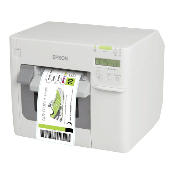
Features of This Product The TM-C3500 is a four-color inkjet label printer providing the processing speed, operability, and reliability required for on-demand label printing. Excellent Usability Support for Wide Variety of Paper The product supports various paper The status of the printer can be checked shapes, forms, and types. -
Page 3: Table Of Contents
Contents Features of This Product ....2 ■ Contents ................3 U"Loading and Replacing Roll Paper" on page Before use ........6 ■ Manuals for This Product ..........6 Downloading the Latest Version.........6 Symbols Used in This Guide..........7 ■ Software Introduction ..........8 ■... - Page 4 ■ Loading Roll Paper............32 Creating and Printing Labels..90 ■ Installing the Maintenance Box ......33 ■ Installing the Ink Cartridges ........35 ■ Creating Labels.............90 ■ Attaching the Paper Ejection Tray......37 ■ Printing Labels..............90 ■ Setting the LCD............39 ■ Creating and Printing Label Data ......91 Display Language..............
- Page 5 Die-cut Labels (Black Marks) and Roll Paper ....186 Troubleshooting.......143 Die-cut Labels (Black Marks) and Fanfold Paper..188 Wristband and Roll Paper (WB-S Series) ......190 ■ A Message is Displayed on the Wristband and Roll Paper (WB-M Series) ....192 Wristband and Roll Paper (WB-L Series) ......195 Operation Panel............
-
Page 6: Before Use
The latest versions of the printer driver, utilities, and manuals can be downloaded from the following URLs. For customers in North America, go to the following web site: <http://www.epson.com/support/> For customers in other countries, go to the following web site: <https://download.epson-biz.com/?service=pos>... -
Page 7: Symbols Used In This Guide
Symbols Used in This Guide The following symbols are used in this guide to indicate important information. Symbols for Safety The symbols shown below are used in this manual in order to ensure safety and proper use of this product and to prevent danger to you and other persons, and property damage. Be sure that you completely understand their meanings before reading this manual. -
Page 8: Software Introduction
Software Introduction The following introduces the software that can be installed from the CD (TM-C3500 Series Set-Up and Utilities Disc) included with the product. Name Overview TM-C35xx Printer Driver Driver to print from Windows applications. The utility (PrinterSetting) for configuring the printer settings can be started from the driver. -
Page 9: Product And Driver Versions
Product and Driver Versions Unless otherwise specified, the explanations in this manual are for the following versions. Product firmware: WAM31000 or later Printer driver: Ver.2.0.0.0 or later How to Check the Product Version You can check the version of the product firmware being used by performing self test printing. Check the first line of the self test print results. -
Page 10: Screens In This Manual
The screens in this manual and the screens actually displayed in Windows may differ depending on the product used and operating system. Unless otherwise specified, the screens in this manual are those when using TM-C3500 in Windows 7. Safety Precautions To ensure safe use of the product, be sure to the read this manual and the other instruction manuals supplied with the product before use. -
Page 11: Cautions On Handling
Cautions on Handling Do not use the product in a location with volatile substances such as WARNING alcohol or paint thinner present, or near fire. Doing so may cause electric shock or fire. Shut down the product immediately if it produces smoke, a strange odor, or unusual noise. -
Page 12: Cautions On Power Supply
Install the cables and optional products in the proper direction CAUTION according to the proper procedures. Failure to install correctly may cause fire or injury. Follow the instructions in this manual to install them properly. "Connecting the Interface Cable" on page Before moving the product, shut down and unplug the product, and make sure that all the cables are disconnected. -
Page 13: Cautions On Ink Cartridges
Do not use a damaged power cord. WARNING There is a risk of electric shock or fire. Contact qualified service personnel for advice if the power cord is damaged. Furthermore, observe the following points so as not to damage the power cord. - Page 14 The product uses ink cartridges equipped with IC chips to manage the CAUTION amount of ink used and other information so ink cartridges are usable even if they are removed and reinstalled. However, if an ink cartridge with not much ink remaining is removed and reinstalled, it may not be usable.
- Page 15 Store the ink cartridges in a place out of reach of children. Epson recommends storing ink cartridges in a cool and dark place. If you wish to use ink cartridges that have been stored in a cold place for a long period of time, leave them for at least 3 hours in a place that is at room temperature before use.
-
Page 16: Caution Label
Caution Label The labels affixed to the product indicate the following cautions. Do not touch the platen. Your hand or clothes may become dirty. CAUTION Clean the platen if it is dirty. (U "Cleaning the Platen" on page 136) To prevent fingers from being trapped, the lock mechanism is activated to stop the cover closing if the unit is raised up from the installation surface. - Page 17 Do not touch the blade of the auto cutter with a hand. Doing so may CAUTION cause injury. Downloaded from ManualsNet.com search engine...
-
Page 18: Paper That Can Be Used
Paper That Can Be Used The following shapes and forms of paper can be used with the printer. For the detailed specifications, check "Paper Specifications" on page 165. Paper Shapes The following shapes of paper can be used. Roll paper Fanfold paper Forms of Paper The following forms of paper can be used. -
Page 19: List Of Paper That Can Be Used
List of Paper That Can Be Used Adhesive Type Category Plain paper Full-page label Matte paper Die-cut labels (with black marks) Synthetic paper Die-cut labels (with gaps) Glossy Roll paper Plain paper Continuous paper Matte paper Continuous paper (with black marks) Wristband Die-cut labels (with black marks) Plain paper... -
Page 20: Part Names And Functions
Part Names and Functions This section describes the main operation parts. Front (power) button Turns on/off the printer. (U "Turning On/Off " on page Release lever Pull this lever towards you to open the roll paper cover. Lock lever (paper ejection guides) Press down this lever to enable adjustment of the paper ejection guides. -
Page 21: Inside
Ink cartridge cover Open this cover to install/replace the ink cartridge. (U "Installing the Ink Cartridges" on page Paper ejection guides These guides are for preventing the paper from getting out of position when ejected. Adjust them to match the paper width. Inside Lock lever (roll paper guides) Pull up this lever to enable adjustment of the roll paper guides. -
Page 22: Operation Panel
Operation Panel Displays messages and the printer status. "Checking the Printer Status" on page 68, U "Setting the LCD" on page Cut button Cuts the paper. Dip switches Operate these switches when configuring the following settings. • When changing the display language of the LCD (U "Display Language"... -
Page 23: Rear
Feed button When the paper has no black marks or gaps between labels, pressing this button once feeds the paper by 15 mm. When the paper has the marks or gaps, pressing this button once feeds the paper to the next mark or gap (the next label or page). -
Page 24: Connectors
Paper feed guide Insert this in the roll paper cover to use fanfold paper. Fanfold paper cover Open this cover to load or replace the fanfold paper. (U "Loading and Replacing Fanfold Paper" on page Connectors 2 3 4 Air vent Exhausts heat generated in the printer to prevent the temperature inside the printer from rising. - Page 25 Link LED Indicates the printer network status. Off: Power is off or network communication stopped On: Network communication established Flashing: Receiving data Status sheet button Press this button to print a status sheet. (U "Checking the Network Settings (Printing Status Sheet)" on page 110) Press and hold this button and turn the printer on, then keep holding down the button for at least 10...
-
Page 26: Setup
Setup This chapter describes the preparation work from installing the printer to getting the printer ready for printing. The printer can also be set up easily by using Install Navi. Install Navi can be started from the supplied Downloaded from ManualsNet.com search engine... -
Page 27: Setup Flow
Setup Flow Installing the Printer Driver (U page Installing the Printer (U page Connecting a Power Supply (U page Connecting the Interface Cable (U page Loading Roll Paper (U page Installing the Maintenance Box (U page Installing the Ink Cartridges (U page Attaching the Paper Ejection Tray (U page... -
Page 28: Installing The Printer Driver
Confirm the processor version of your operating system and then download the appropriate printer driver. For customers in North America, go to the following web site: <http://www.epson.com/support/> For customers in other countries, go to the following web site: <https://download.epson-biz.com/?service=pos> Downloaded from ManualsNet.com... -
Page 29: Installing The Printer
Installing the Printer Removing the Protective Tape Protective tape is affixed for protection against shock during transportation. Remove the tape before installation. The protective tape and packaging box will be required for future IMPORTANT transportation. Keep them in a safe place. Downloaded from ManualsNet.com search engine... -
Page 30: Installation
Installation Provide sufficient space in a location appropriate for installation. 10 cm {3.93"} 10 cm {3.93"} Location Appropriate for Installation Install the printer in a location as follows. • On a level and stable surface with sufficient strength to support the weight of the printer (approx. -
Page 31: Connecting A Power Supply
Connecting a Power Supply Connect a power supply by following the steps below. Read the precautions on the power supply carefully before connecting the WARNING power supply. (U "Cautions on Power Supply" on page Do not use other than the specified AC adapter (AC adapter, K model number: M248A). -
Page 32: Connecting The Interface Cable
Connecting the Interface Cable Connect the interface cable to be used to the connector on the rear side of the printer. "Connectors" on page When connecting a USB cable, pass the cable through the wire saddle to prevent accidental disconnection. Wire Saddle Setting the IP Address If the interface to be used is Ethernet (LAN cable connection), you need to configure the... -
Page 33: Installing The Maintenance Box
Installing the Maintenance Box The maintenance box is a container for the waste ink discharged during cleaning and printing. This section describes the procedure for installing the maintenance box for the first time. When replacing the maintenance box, see "Replacing the Maintenance Box" on page 45, and then follow the procedure in this section. - Page 34 Push the maintenance box into the printer until it clicks into place. Close the maintenance box cover. Engage the hook of the cover with the printer, and then close the cover. Downloaded from ManualsNet.com search engine...
-
Page 35: Installing The Ink Cartridges
Installing the Ink Cartridges This section describes the procedure for installing the ink cartridges and performing ink charging for the first time. When replacing an ink cartridge, see "Replacing the Ink Cartridges" on page 44, and then follow the procedure in this section. Read the precautions on handling carefully before installing the ink cartridges. - Page 36 Push the ink cartridges of all four colors gently into the printer until they click into place. Make sure that the color of each cartridge label matches the color of the label on the cartridge insertion part. Close the ink cartridge cover. Ink charging starts.
-
Page 37: Attaching The Paper Ejection Tray
Attaching the Paper Ejection Tray Attaching the supplied paper ejection tray to the printer allows you to temporarily collect printed labels. The paper ejection tray can hold the paper of the following sizes. Maximum paper size: 105 (W) x 148 (L) mm Minimum paper size: 76 (W) x 54 (L) mm In the case of roll paper, the paper is curled so if multiple labels or sheets are Note... - Page 38 Extend the paper ejection tray until the paper length indication matches with the length of your paper. Push in lever at the bottom right of the paper ejection tray to lock the tray in place. Downloaded from ManualsNet.com search engine...
-
Page 39: Setting The Lcd
Setting the LCD Configure the various settings of the LCD. Display Language Set the display language of the LCD by following the steps below. Turn the printer off before removing the dip switch cover. If you remove the CAUTION cover while the power is on, the printer may fail due to a short circuit. Turn the printer off. - Page 40 Use an object with a sharp tip to operate the dip switches. The dip switches are numbered in order from the left. Up is the ON state and down is the OFF state. The dip switch settings for each language are shown below.
-
Page 41: Contrast Adjustment
Contrast Adjustment Adjust the contrast of the LCD by following the steps below. The changed setting is retained even if the power is turned off. Turn the printer on. (U "Turning the Power On" on page Open the ink cartridge cover. Press the LCD contrast adjustment buttons to adjust the contrast. -
Page 42: Basic Operation
Basic Operation This chapter describes the basic operating procedures of the printer. Turning On/Off This section describes how to turn the printer on/off. Turning the Power On Hold down the (power) button for at least 1 second until the (power) LED turns on. Downloaded from ManualsNet.com search engine... -
Page 43: Turning The Power Off
Turning the Power Off Hold down the (power) button for at least 1 second until the (power) LED turns off. • Do not remove and insert the power plug from/to the outlet while the printer is powered on. Doing so may cause electric shock or fire. •... -
Page 44: Replacing The Ink Cartridges
Replacing the Ink Cartridges This section describes how to replace the ink cartridges. Checking Amount of Ink Remaining The ink LED lights and the LCD indicates REPLACE INK when it is time to replace an ink cartridge. You can check which ink cartridge needs to be replaced on the LCD. "Replacement Timing of Consumables"... -
Page 45: Replacing The Maintenance Box
Replacing the Maintenance Box This section describes how to replace the maintenance box. Checking the Amount of Empty Space in the Maintenance Box The ink LED lights and the LCD indicates REPLACE MAINTENANCE BOX when it is time to replace the maintenance box. (U "Replacement Timing of Consumables"... -
Page 46: Loading And Replacing Roll Paper
Loading and Replacing Roll Paper This section describes how to load and replace roll paper. As shown below, the procedure differs depending on the size and form (roll or fanfold) of the paper before and after the replacement. When replacing paper with a different shape, form, or type of paper, change the media settings of the printer driver before loading the paper. - Page 47 How to Load and Replace Roll Paper Turn the printer on Check that the printer is powered on. (U "Turning the Power On" on page Start PrinterSetting and set the media source Start PrinterSetting from the computer and set the media source to Roll paper. After changing the setting, click Apply Settings and restart the printer.
- Page 48 Open the roll paper cover Pull the release lever toward you to open the roll paper cover. If there is used roll paper or a core remaining inside the printer, remove it. Remove the paper feed guide Pull the paper feed guide to remove it. Downloaded from ManualsNet.com search engine...
- Page 49 Release the lock of the roll paper guides Pull up the lock lever of the roll paper guides. Adjust the roll paper guides to match the paper width Widen the roll paper guides by hand. Downloaded from ManualsNet.com search engine...
- Page 50 Load the roll paper Insert the roll paper between the roll paper guides. Print side Lock the roll paper guides Push down the lock lever of the roll paper cover. Downloaded from ManualsNet.com search engine...
- Page 51 Adjust the platen shutters to match the paper width Open/close the shutters on the platen to match the paper width. (U "Adjusting the Shutters" on page Downloaded from ManualsNet.com search engine...
- Page 52 Release the lock of the paper ejection guides Push down the lock lever of the paper ejection guides and then widen the paper ejection guides. Downloaded from ManualsNet.com search engine...
- Page 53 Pull out the leading edge of the roll paper Pull out the leading edge of the roll paper with the print side facing upward. Adjust the paper ejection guides to match the paper width Move the paper ejection guides inward to precisely align them to the width of the pulled out paper.
- Page 54 Lock the paper ejection guides Pull up the lock lever of the paper ejection guides toward you until it clicks into place. Close the roll paper cover Keeping the leading edge of the roll paper pulled out, close the roll paper cover. Downloaded from ManualsNet.com search engine...
- Page 55 Check the LCD Check that the LCD of the printer is indicating R. If it is not indicated, load the paper again or set the setting in PrinterSetting again. READY Loading of the roll paper is now complete. Downloaded from ManualsNet.com search engine...
-
Page 56: Loading And Replacing Fanfold Paper
Loading and Replacing Fanfold Paper This section describes how to load and replace fanfold paper. As shown below, the procedure differs depending on the size and form (roll or fanfold) of the paper before and after the replacement. When replacing paper with a different shape, form, or type of paper, change the media settings of the printer driver before loading the paper. - Page 57 How to Load and Replace Fanfold Paper Turn the printer on Check that the printer is powered on. (U "Turning the Power On" on page Start PrinterSetting and set the media source Start PrinterSetting from the computer and set the media source to Fanfold paper. After changing the setting, click Apply Settings and restart the printer.
- Page 58 Open the roll paper cover Pull the release lever toward you to open the roll paper cover. If there is paper remaining inside the printer, remove it. It may cause a paper jam. Attach the paper feed guide Open the fanfold paper cover and remove the paper feed guide. Insert the paper feed guide into the grooves inside the roll paper cover.
- Page 59 Adjust the platen shutters to match the paper width Open/close the shutters on the platen to match the paper width. (U "Adjusting the Shutters" on page Release the lock of the paper ejection guides Push down the lock lever of the paper ejection guides and then widen the paper ejection guides.
- Page 60 Adjust the paper ejection guides to match the paper width Move the paper ejection guides inward to precisely align them to the paper width. Lock the paper ejection guides Pull up the lock lever of the paper ejection guides toward you until it clicks into place. Downloaded from ManualsNet.com search engine...
- Page 61 Close the roll paper cover Open the fanfold paper cover Downloaded from ManualsNet.com search engine...
- Page 62 Release the lock of the fanfold paper guides Pull up the lock lever of the fanfold paper guides. Adjust the fanfold paper guides to match the paper width Move the fanfold paper guides to precisely align them to the paper width. Downloaded from ManualsNet.com search engine...
- Page 63 Lock the fanfold paper guides Push down the lock lever of the fanfold paper guides. Insert the leading edge of the paper Insert the leading edge of the paper with the print side facing upward. When the paper is inserted about 100 mm, it will be fed inside the printer automatically. At this time, check that the roll paper cover at the front of the printer is closed.
- Page 64 Close the fanfold paper cover Close the fanfold paper cover. It prevents liquid and dust from entering inside the printer. Adjust the position of the fanfold paper Place the fanfold paper at least 40 mm away from the rear of the printer. Also, check that the paper is vertical in relation to the paper feed slot.
- Page 65 Check the LCD Check that the LCD of the printer is indicating F. If it is not indicated, load the paper again or set the setting in PrinterSetting again. READY Loading of the fanfold paper is now complete. Downloaded from ManualsNet.com search engine...
-
Page 66: Adjusting The Shutters
Adjusting the Shutters Inside the roll paper cover, there are shutters for adjusting paper suction for during printing. The shutters need to be correctly opened/closed to match the paper width used. To open/close them, move them with a finger. Furthermore, the paper width can be checked on the label at the top of the main unit. - Page 67 Paper width / Backing paper width Shutter state 97 mm or more and less than 112 mm Open only the three inner rows of shutters 112 mm Open all shutters Downloaded from ManualsNet.com search engine...
-
Page 68: Checking The Printer Status
Checking the Printer Status The status of the printer can be checked from a combination of the LEDs lighting/flashing and the LCD display. By using the self-test printing, you can check the printer settings and condition of the nozzles. The language of the LCD can be switched with the dip switches. (U "Display Note Language"... -
Page 69: Statuses And Errors
The ink cartridge is expended; replace with a REPLACE INK new ink cartridge. There is no free space remaining so the maintenance box needs to be replaced. REPLACE MAINTENANCE BOX Printing is not possible until a new maintenance box is installed. An ink cartridge is not installed. - Page 70 LCD display Printer status Status Power Paper — — — PAPER OUT No paper — — PAPER OUT ERROR No paper error Roll paper cover is — — ROLL COVER OPEN open Ink cartridge cover is — — INK COVER OPEN open —...
-
Page 71: Self-Test Printing
Self-Test Printing The self-test printing function allows you to print the firmware version, the printer settings such as the nozzle check mode and media detection settings, and nozzle check patterns that can be used to check the nozzles for clogging. The printer will print on the loaded paper regardless of the media settings of the printer driver. - Page 72 While pressing the Feed button, press and hold the (power) button. Do not release the (power) button until the (power) LED starts to flash. Self test printing begins. The printed items are as follows. Firmware version Total number of paper cutting operations Nozzle check mode (U "Auto Nozzle Check System"...
-
Page 73: How To Use The Printer Driver
If you wish to reflect the settings in only the application software you are using, display the printer driver from the application software. Click Print or Print Settings in the File menu of the application. Select EPSON TM-C3500 in Printer. Click Properties or Advanced. The printer driver appears. - Page 74 Click Printers and Faxes in the Start menu. • Windows XP Home Edition: Click Control Panel in the Start menu and then click Printers and Faxes. Right-click EPSON TM-C3500 and then click Printing preferences. The printer driver appears. Downloaded from ManualsNet.com...
-
Page 75: Printer Driver Screen Configuration
Printer Driver Screen Configuration The printer driver is equipped with a help function. Right-click an item and then click Help to display an explanation on the item. Current settings pane Displays the current driver setting state. General tab Set the basic items required for printing such as the size and form of media. Options tab Set the settings on this tab when you wish to adjust the print orientation, number of copies, and print position. -
Page 76: Registering Paper (Media Definition)
Registering Paper (Media Definition) The size, form, type, and other settings of frequently used paper can be registered to the printer driver as a media definition. This is convenient because you will not need to set the media settings of the driver when printing from an application if you register a media definition in advance. - Page 77 Click the New button. The New screen appears. Enter and set the settings from Media Name to Settings For Paper Handling After Print according to the paper to be used Media Name Enter the name of the media definition. This is the name displayed when you select a paper size from an application. Downloaded from ManualsNet.com search engine...
- Page 78 Media Width Enter the paper width. • Continuous Paper: Input paper width as is • Full-page label: Paper width excluding backing paper Full-page Label • Die-cut labels: Paper width excluding backing paper and waste surrounding the labels Downloaded from ManualsNet.com search engine...
- Page 79 Media Length Enter the paper length. • Continuous paper and full-page labels: Length of the print range (length of one page) Continuous Paper Full-page label • Die-cut label: Paper length excluding waste surrounding the labels Media Form Select the paper form. (U "Forms of Paper"...
- Page 80 Media Saving (continuous paper and full-page labels only) Select the media saving setting of the paper. You can set not to create margins before and after the print data for one page. Top margin Paper feed direction Print data Bottom margin •...
- Page 81 Settings For Paper Handling After Print Configure the setting for cutting paper after printing. • Auto Cut (After Every Page): Cuts automatically after printing each page. • Auto Cut (Only After Last Page): Cuts automatically only after printing the last page. •...
- Page 82 • No Auto Cut (Feed To Peel Off Position): Feeds the paper to the label peel off position after printing. Stop position Paper feed direction • No Auto Cut (Feed To Cut Position): Feeds the paper to the cut position after printing. Stop position Paper feed direction •...
- Page 83 Advanced Adjust the print colors and configure the print orientation and other settings. Click OK. Check that the registered media name is displayed in the Media Definition screen and then click Close. Downloaded from ManualsNet.com search engine...
- Page 84 Check that you can select the registered media name in Media Name on the General tab. Click the OK button to close the driver. Paper registration (media definition) is now complete. Downloaded from ManualsNet.com search engine...
-
Page 85: Editing And Deleting
Editing and Deleting Edit and delete registered media definitions by following the steps below. Display the printer driver. (U "How to Display the Printer Driver" on page Click the Media Definition button on the General tab. The Media Definition screen appears. Downloaded from ManualsNet.com search engine... - Page 86 Click to select the media definition you wish to edit or delete. Downloaded from ManualsNet.com search engine...
- Page 87 If you wish to change the definition settings, click the Edit button. The Edit screen appears and you can change the definition. If you wish to delete the definition, click the Delete button. A screen appears and if you click the OK button, the definition is deleted. Editing or deleting a media definition is now complete.
-
Page 88: Borderless Printing
Borderless Printing This section describes the Borderless Printing function on the Options tab of the printer driver. When the Borderless Printing check box is selected, the driver does not provide margins. If you clear the check box, a margin of 1.5 mm will be provided at each of the top, bottom, left, and right of the print page. -
Page 89: Uninstalling The Printer Driver
Uninstalling the Printer Driver To uninstall the printer driver from the computer, follow the steps below. Turn the printer off. (U "Turning the Power Off" on page Exit all applications running on the computer. Open Uninstall a program (or Add or Remove Programs). •... -
Page 90: Creating And Printing Labels
This section describes the basic printing procedure. Open the file to be printed from application software. Select File - Print and then select EPSON TM-C3500 from Printer. Click Properties (or Advanced) to display the screen of the printer driver. Enter a paper size that matches the paper being used or select a media definition that was registered in advance. -
Page 91: Creating And Printing Label Data
Creating and Printing Label Data Here we will describe the example of the procedure for creating a label data using Microsoft® Word 2010, and printing it. When actually printing, the procedure needs to be varied to match your operating environment. •... - Page 92 The operation flow is shown below. Registering a Media Definition Register the settings according to the paper to be used in the printer driver. Prepare Microsoft® Word Set the margins and paper size of the document. Design label Design the label in accordance with the purpose. Print Print the label from the printer.
- Page 93 Click the New button. The New screen appears. Downloaded from ManualsNet.com search engine...
- Page 94 Enter and set the settings from Media Name to Settings For Paper Handling After Print as shown below according to the paper to be used. "Registering Paper (Media Definition)" on page Media Name: 72 x 51 Die-cut Label (Matte) Media Width: 72.0 Media Length: 51.0 Media Form: Die-cut Label (Gap) Media type: Matte paper...
- Page 95 Click OK. Check that the registered media name is displayed in the Media Definition screen and then click Close. Downloaded from ManualsNet.com search engine...
- Page 96 Check that you can select the registered media name in Media Name on the General tab. Click the OK button to close the driver. Start Microsoft® Word 2010 and select EPSON TM-C3500 from File - Print - Printer. Click Custom Margins from the Margins pull-down menu, and then set the top, bottom, left, and right margins to 1.5 mm.
-
Page 97: Borderless Printing Of Die-Cut Labels
Borderless Printing of Die-cut Labels This section describes the recommended conditions for printing die-cut labels without borders (printing with no margins at the top, bottom, left, and right of labels). With borderless printing, the print may extend onto the backing paper depending on the actual print position and position the paper is loaded. -
Page 98: Printer Driver Settings
Printer Driver Settings • Set a print area that is 1.5 mm larger at the top, bottom, left, and right than the paper size. • Select Continuous paper (Blackmark) for the media form. • Select the Borderless Printing check box. Setting Example This section shows an example of setting the driver for borderless printing. - Page 99 Printable area 70.0 mm (Backing paper width) 66.0 mm (label width including waste) 63.0 mm (print area width) 60.0 mm (label width) Paper feed direction 1.5 mm 1.5 mm 1.5 mm 1.5 mm 2.0 mm 2.0 mm Print area of Media Definition to be specified in the printer driver Area to place print data (Top: Rectangle of 63.0 x 38.0 mm/Bottom: Oval of 63.0 x 38.0 mm) Label area...
-
Page 100: Advanced Usage
Advanced Usage This chapter describes the how to use the printer in specific applications. Functions and Operating Procedures of the Printer Buzzer This section describes the functions and settings of the buzzer. The buzzer sounds when printing is not possible and when printing completes. This allows you to check the status of the printer even when you are in a location away from the printer. - Page 101 Check that the printer is powered off. Open the ink cartridge cover and remove the dip switch cover. Use an object with a sharp tip to operate the dip switches. The dip switches are numbered in order from the left. Up is the ON state and down is the OFF state.
- Page 102 Display the printer driver. (U "How to Display the Printer Driver" on page Select the Printer Utilities tab and then click Printer Setting Utility. The TM-C3500 PrinterSetting screen appears. Select Advanced Settings - Notification Settings. Downloaded from ManualsNet.com...
- Page 103 The Notification Settings screen appears. Select a setting from the Beep Notification Setting at an Error pull-down menu. Click Apply Settings. Turn the printer on. When printing completes When printing completes, the buzzer sounds for 0.3 seconds. The buzzer setting can be configured in the printer driver.
-
Page 104: Auto Nozzle Check System
Auto Nozzle Check System The printer is equipped with an auto nozzle check system to ensure stable print quality. It checks the print head at regular intervals and run a head cleaning if nozzle clogging is detected. You can select one of the following four modes of the auto nozzle check system. Print Nozzle Check Mode Description... - Page 105 "How to Display the Printer Driver" on page Select the Printer Utilities tab and then click Printer Setting Utility. The TM-C3500 PrinterSetting screen appears. Select General - Printer Operation Settings. The Printer Operation Settings screen appears. Select a setting from the Nozzle Check Mode pull-down menu.
- Page 106 Click Apply Settings. Setting is now complete. Downloaded from ManualsNet.com search engine...
-
Page 107: Network Settings
Network Settings This section describes the network settings. The printer can use network settings assigned automatically from the DHCP (Dynamic Host Configuration Protocol) server of a broadband router or other device. Alternatively, you can set the IP address and other settings manually. Setting Methods There are the following ways to configure the network settings. -
Page 108: Default Network Settings
Address still set to Auto, printing may be impossible. It is recommended to Note consult with your network administrator or using one of the utilities (Install Navi, EpsonNet Config, EPSON Deployment Tool, etc.) to set a static IP address. (U "Network Settings" on page... - Page 109 Restoring the Default Network Settings The following describes how to restore the default network settings. Check that the printer is powered off. Press and hold the status sheet button and turn the printer on, then keep holding down the button for at least 10 seconds. (U "Connectors"...
-
Page 110: Checking The Network Settings (Printing Status Sheet)
Checking the Network Settings (Printing Status Sheet) If you press the status sheet button on the rear of the printer, the following status sheet is printed. You can check the network settings on the status sheet. Downloaded from ManualsNet.com search engine... -
Page 111: Epsonnet Config (Web Version)
EpsonNet Config (Web Version) This section describes the functions and operating procedures of EpsonNet Config (Web version). It allows you to acquire the information and configure the network settings of the printer from the browser of a computer or tablet via the network. Connect the computer or tablet to the same network as the printer. - Page 112 The Main screen appears. Click the item to be set or checked. The Password Input screen appears. Enter the password. Password: epson (default setting) The screen of the selected item appears. Downloaded from ManualsNet.com search engine...
-
Page 113: Notification Settings For Fatal Errors
Notification Settings for Fatal Errors The EPSON Status Monitor 3 screen appears when a fatal error has occurred. The error items are as follows. • Ambient Temperature Error: When the temperature inside the printer has risen • Service Required: When an error requiring repair has occurred •... - Page 114 The following describes how to change the settings. Display the printer driver. (U "How to Display the Printer Driver" on page Select the Driver Utilities tab and then click Notification Settings for Fatal Errors. The Notification Settings for Fatal Errors screen appears. Clear the check boxes of the items for which to not display the screen when an error occurs and then click OK.
-
Page 115: Printersetting Functions And Operating Procedures
Start PrinterSetting by following the steps below. Turn the printer on. Display the printer driver. (U "How to Display the Printer Driver" on page Select the Printer Utilities tab and then click Printer Setting Utility. The TM-C3500 PrinterSetting screen appears. Downloaded from ManualsNet.com search engine... -
Page 116: Printersetting Screen Configuration
PrinterSetting Screen Configuration PrinterSetting is equipped with a help function. Click the Help button to display explanations on the setting items. Menu Displays a menu of the setting items. (U "PrinterSetting Functions" on page 117) Model Name Displays the printer queue name. Port Displays the computer port name. -
Page 117: Printersetting Functions
Apply Settings Applies the settings to the printer. Help Displays the Help screen. Setting area Displays the setting items. PrinterSetting Functions The following printer settings can be changed in PrinterSetting. Menu Setting item Description General Media Media source settings Set the source according to the paper Settings loaded in the printer. - Page 118 Menu Setting item Description Advanced Notification Beep Notification Setting at Set whether or not to notify with a Settings Settings an Error beep when an error occurs. LED Notification Setting at Set whether or not the Ink LED Ink Low flashes when the amount of ink becomes low.
-
Page 119: Applying The Printersetting Settings
Applying the PrinterSetting Settings Apply the settings that you set on each screen to the printer by following the steps below. Change the settings of the printer on each setting screen in PrinterSetting. Click Apply Settings. A confirmation screen appears. Click Yes to send the setting to the printer. Click OK to close the screen. -
Page 120: Paper Feed Adjustment
Paper Feed Adjustment Make adjustments when the auto cut position does not match or the print start position shifts for the paper being used. Setting Description Cut Position Adjustment Adjust the cut position. The increment is 1/180 inch. This can be page 121) adjusted within the range of -63 to 63. - Page 121 How to Adjust the Cut Position Adjust the cut position to match the media form used. When using media with a perforated line, adjust the cut position so that the perforated line is not cut. Media Form Description • When the adjustment value is +, the cut position moves closer to the reference position (print start position).
- Page 122 Media Form Description • When the adjustment value is +, the cut position moves closer to the reference position (print start position). • When the adjustment value is –, the cut position moves away from the reference position (print start position). Backing paper Label Reference position...
- Page 123 Media Form Description • When the adjustment value is +, the cut position moves closer to the reference position (print start position). • When the adjustment value is –, the cut position moves away from the reference position (print start position). Backing paper Reference position (print start position)
- Page 124 How to Adjust the Print Start Position (Vertical Direction) Adjust the print start position in the vertical direction to match the media form used. When the print start position is adjusted, the cut position is also adjusted at the same time. Media Form Description •...
- Page 125 Media Form Description • When the adjustment value is +, the print start position and cut position move away from the reference position (black mark position). • When the adjustment value is –, the print start position and cut position move closer to the reference position (black mark position). Backing paper Reference position (black mark position)
- Page 126 How to Adjust the Print Start Position (Horizontal Direction) Adjust the print start position in the horizontal direction. • When the adjustment value is +, the position shifts to the left when viewed from the printer. • When the adjustment value is –, the position shifts to the right when viewed from the printer. Paper feed Printable area direction...
-
Page 127: Sensor Adjustment
Sensor Adjustment The threshold value of a sensor can be adjusted when the gaps between the labels or the black marks of the paper being used cannot be detected. Click the Start adjustment button of the sensor to be adjusted. A confirmation screen appears. -
Page 128: Print Head Alignment
Print Head Alignment Align the print head if white or black banding appears on printouts, vertical and horizontal lines are skewed or misaligned, or text looks blurred. Depending on the print quality problem, aligning the print head makes the problem less noticeable, but cannot completely resolve it. If the problem Note cannot be resolved, refer to "Problems with Print Quality"... - Page 129 The Banding Adjustment screen appears. Look at the print results and then select a setting value. After selecting a setting value, click OK. If there are gaps (white banding), make the adjustment in the + direction. If there is overlapping in the print results (black banding), make the adjustment in the – direction.
- Page 130 Print adjustment sheet Load die-cut label, continuous paper, or full-page label paper with a length of 140 mm or more into the printer. Select Print adjustment sheet from Adjustment Method and then click Start adjustment. The screen to print a sheet for feed adjustment appears. Check that paper is loaded in the printer and then click OK.
- Page 131 Adjustment sheet print example (In the case of these patterns, select “3”.) White banding White banding Black banding Black banding An adjustment start confirmation screen appears. Click Yes. When adjustment is complete, the Finish screen appears. Click OK. Downloaded from ManualsNet.com search engine...
- Page 132 Bi-directional Printing Adjustment When printed vertical or horizontal lines look skewed or misaligned, or when printed text looks blurred, perform the Bi-directional Printing Adjustment. Set whether or not to perform bi-directional printing in Print Quality - Note Advanced - Bidirectional Printing. Load die-cut labels with a length of 140 mm or more, continuous paper, or full-page label paper into the printer.
- Page 133 The adjustment sheet is printed and the Banding Adjustment screen appears. Check the sheet and then select the number of the pattern with the least gaps or overlapping and click OK. Adjustment sheet print example (In the case of these patterns, select “6”.) White banding White banding Overlapping...
- Page 134 The screen to print a sheet for bi-directional printing (720x360) adjustment appears. Check that paper is loaded in the printer and then click OK. Downloaded from ManualsNet.com search engine...
- Page 135 The adjustment sheet is printed and the Banding Adjustment screen appears. Check the sheet and then select the number of the pattern with the least gaps or overlapping and click OK. Adjustment sheet print example (In the case of these patterns, select “7”.) White banding White banding Overlapping...
-
Page 136: Maintenance
Maintenance This chapter describes how to carry out maintenance of the printer. Cleaning the Exterior Do not use alcohol, benzine, thinner, trichloroethylene, or ketone based solvent to clean the exterior of the printer. Doing so may deform or damage CAUTION the plastic and rubber parts. - Page 137 Turn the printer off, and then disconnect the AC cable from the outlet. Pull the release lever toward you to open the roll paper cover. Remove the roll paper or fanfold paper. Use the non-woven fabric for platen cleaning to clean the platen. Downloaded from ManualsNet.com search engine...
- Page 138 Use cotton swabs to clean the holes and around the holes. If the holes are blocked, be sure remove the dirt to unblock the holes. Close the roll paper cover. Cleaning of the platen is now complete. Downloaded from ManualsNet.com search engine...
-
Page 139: Cleaning The Auto Cutter
Cleaning the Auto Cutter The fixed blade of the auto cutter may become unable to cut cleanly due to the adhesive of label paper adhering to it. Perform cleaning by following the steps below. Turn the printer off, and then disconnect the AC cable from the outlet. Open the roll paper cover and remove the paper. -
Page 140: Cleaning The Printer Head
Cleaning the Printer Head If the nozzles are clogged, faint colors, banding, or unintended colors appear on printouts. When such print quality problems occur, print nozzle check patterns and check for nozzle clogging. Normal Clogging When the printed patterns show the nozzle clogging state, run a head cleaning. Downloaded from ManualsNet.com search engine... -
Page 141: Printing Nozzle Check Patterns
Printing Nozzle Check Patterns You can print the nozzle check patterns using the self test printing function (U "Self-Test Printing" on page 71) or the printer driver’s nozzle check function. Printing from Printer Driver Start the printer driver. (U "How to Display the Printer Driver" on page Click Nozzle Check on the Printer Utilities tab. -
Page 142: Head Cleaning
Head Cleaning • Do not turn off the power or open the covers during head cleaning. Doing so may cause printing malfunction. • Do not run the head cleaning more than necessary. Ink is consumed because ink is discharged from the head to clean it. IMPORTANT •... -
Page 143: Troubleshooting
Troubleshooting This chapter describes how to resolve problems. Trouble Reference A message is displayed on the operation panel page 144 Problems with print quality page 147 Paper is fed and ejected, and an error occurs page 155 Paper is jammed page 156 A message is displayed on the computer screen page 157... -
Page 144: A Message Is Displayed On The Operation Panel
A Message is Displayed on the Operation Panel If a message appears on the LCD of the operation panel, try the solution described below. LCD display Error details Solution and Reference • Use paper that matches that set in the media detection settings. The form of the loaded •... - Page 145 LCD display Error details Solution and Reference Install an ink cartridge with a An ink cartridge is not sufficient amount of ink remaining. NO INK CARTRIDGE installed. "Installing the Ink Cartridges" on page • Reinstall the ink cartridge. • If the error reoccurs, replace the The ink cartridge INK READ ERROR ink cartridge with a new one.
- Page 146 LCD display Error details Solution and Reference 1. Turn the printer off. (U "Turning the Power Off" on page One of the following is occurring. 2. Open the roll paper cover. • Paper jam 3. Check that no paper is jammed. If PRINTER ERROR ## •...
-
Page 147: Problems With Print Quality
Problems with Print Quality Find a symptom that is similar to your problem from the table below, then go to the linked page to see the solutions. Symptoms Explanation Horizontal white banding appears on White printouts (page 149) banding White or black banding appears near the edges on printouts (page 149) - Page 148 Symptoms Explanation Printed characters look blurred or look Blurred like printed twice (page 152) Double printing ABCDEFGABCDEFGABC ABCDEFGABCDEFGABC • Printed colors are wrong (page 152) • Print position shifts (page 152) • Paper is smeared or smudged wit ink (page 153) •...
-
Page 149: Horizontal White Banding
Horizontal White Banding Cause Solution and Reference The nozzles are clogging. Print the nozzle check patterns to check the nozzles for clogging. If the nozzles are clogging, run a head cleaning by pressing the Cleaning button for at least 3 seconds. When Nozzle Check Mode is other than Anti-missing dot mode, missing dots are permitted. -
Page 150: White Or Black Banding
White or Black Banding If your printouts are faint, or white or black banding appears, follow the procedure below to resolve the problem efficiently. Banding at a regular interval of 25.4 mm (1 inch) in the paper feed direction can be reduced but not completely eliminated. Cause Solution and Reference The paper is not loaded correctly. -
Page 151: Unintended Top And Bottom Margins Are Generated
Unintended Top and Bottom Margins are Generated If the backing paper of die-cut label sheet that does not have waste surrounding labels is too thin (transmittance is high), the printer may not be able to detect the labels and cause unintended top and bottom margins on each label. -
Page 152: Printed Characters Look Blurred
Printed Characters Look Blurred Cause Solution and Reference Blurred print may occur when the Perform the Bi-directional Printing Adjustment. printer settings are not Click Printer Setting Utility on the Printer Utilities tab of the appropriate for the thickness of printer driver to display PrinterSetting. Then execute Bi- the paper. -
Page 153: Paper Is Smeared Or Smudged With Ink
Paper is Smeared or Smudged with Ink Cause Solution and Reference The paper width and the shutters If the paper width and shutters on the platen do not match, on the platen do not match. rising up of the paper may cause the paper and print head to rub against each other, leading to the paper becoming dirty. -
Page 154: Margins Are Generated On Printed Labels
Margins are Generated on Printed Labels Cause Solution and Reference This is normal, and not a failure of If Borderless Printing is not enabled on Options tab of the the printer. printer driver, an area which is the label size excluding margins of 1.5 mm at the top, bottom, left, and right becomes the printable size. -
Page 155: Paper Is Fed And Ejected, And An Error Occurs
Paper is Fed and Ejected, and an Error Occurs • When the media form is full-page label, continuous paper, or full-page label with transparent backing paper Cause Solution and Reference The paper being used differs Check the paper being used and Media detection settings of from that of Media detection the printer. -
Page 156: Paper Is Jammed
• When the media form is die-cut label (black marks) or continuous paper (black marks) Cause Solution and Reference The paper being used differs Check the paper being used and Media detection settings of from that of Media detection the printer. (U "PrinterSetting Functions and Operating settings. -
Page 157: A Message Is Displayed On The Computer
A Message is Displayed on the Computer If the following screen appears, resolve the problem following the instructions on the screen. Printer status Solution Downloaded from ManualsNet.com search engine... -
Page 158: Printing From A Computer Is Impossible Or Becomes Suddenly Impossible
Printing from a Computer is Impossible or Becomes Suddenly Impossible Checking Whether the Printer Driver Is Installed Check whether or not the required software and applications are installed on the computer. To print with this printer, a printer driver is required. Check whether or not the printer driver is installed by following the steps below. - Page 159 If the printer is installed multiple times, copies of the printer driver may be created. If there is more than one printer icon and you find a copied one such as “TM-C3500 (Copy 1)”, right-click on the copied icon and then delete it by clicking Remove device.
-
Page 160: The Printer Does Not Turn On
The Printer Does Not Turn On Check that the power cable is connected to the printer and outlet properly. (U "Connecting a Power Supply" on page Downloaded from ManualsNet.com search engine... -
Page 161: Specifications
AC adapter, and roll paper) Use a shielded cable of category 5 or higher for the LAN cable. CAUTION Print speeds are measurement results obtained under Epson’s operating conditions. They will vary depending on the print data and environmental Note conditions. -
Page 162: Electrical Specifications
0.85 A Power Operating Average of approx. 30 W (50 W during peak) consumption* Standby Average of approx. 2.5 W Power off Average of approx. 0.3 W ∗ : According to Epson's operating conditions when operating. Downloaded from ManualsNet.com search engine... -
Page 163: Overall Dimensions
Overall dimensions • Height: 261 mm • Width: 310 mm • Depth: 283 mm 465 (when paper ejection tray extended) 396 (when paper ejection tray is retracted) [Unit: mm] Downloaded from ManualsNet.com search engine... -
Page 164: Environmental Specifications
(elevation) Not operating 850 to 1060 hPa (approx. 0 to 1500 m above sea level) (including in transportation) Noise Operating Approx. 58 dB (ANSI Bystander position) (including auto Based on Epson evaluation conditions. cutting operation) Downloaded from ManualsNet.com search engine... -
Page 165: Paper Specifications
Paper Specifications The specifications of paper that can be used with this printer are as follows. Continuous Paper Paper type Plain paper / matte paper Form Roll paper Paper width 30 to 108 mm Paper thickness 0.084 to 0.124 mm Roll paper core Outer diameter: 44.1 mm or more Outer diameter... -
Page 166: Continuous Paper (Black Marks)
Continuous Paper (Black Marks) <Back side> <Print side> Mark center position Paper width center Paper width center Paper feed direction Perforation position 0.5 mm or more Fanfold paper Paper Mark width Paper type Plain paper / matte paper Form Roll paper Paper width 30 to 108 mm Black mark width... - Page 167 Paper type Plain paper / matte paper Form Fanfold paper Paper width 50 to 108 mm Black mark width 13 mm or more Black mark length 4 mm or more (margin part 4 mm or more) 8.5 ± 1 mm Black mark center position Black mark interval 8 to 304.8 mm...
-
Page 168: Full-Page Label
Full-page Label Backing paper width Backing paper Label Label width Waste part Waste part Paper type Plain paper label / matte paper label / synthetic paper label / glossy paper label Form Roll paper Backing paper width 30 to 112 mm Label width 25.4 to 108 mm 2 ±... -
Page 169: Die-Cut Label (Gap)
Die-cut label (Gap) Backing paper width Corner R Backing paper Label Label width Waste part Waste part Paper type Plain paper label / matte paper label / synthetic paper label / glossy paper label Form Roll paper Backing paper width 30 to 112 mm Label width 25.4 to 108 mm... -
Page 170: Die-Cut Label (Black Marks)
• Paper with holes or cutouts cannot be used. • If the backing is synthetic paper or film, cutting by hand will be difficult IMPORTANT even if there are perforated lines, so do not use perforated lines. Depending on the shape of die-cut labels, the labels may peel off their backing paper inside the printer. - Page 171 Paper type Plain paper label / matte paper label / glossy paper label: Form Roll paper Backing paper width 30 to 112 mm Label width 25.4 to 108 mm Label length 8 to 1117.6 mm Gap between labels 3 to 6 mm 2 ±...
- Page 172 Paper type Plain paper label / matte paper label: Form Fanfold paper Backing paper width 50 to 112 mm Label width 46 to 108 mm Label length 8 to 301.8 mm Gap between labels 3 to 6 mm 2 ± 0.5 mm Waste part on the left and right Waste width 1.5 mm or more...
- Page 173 • Paper with holes or cutouts cannot be used. • Auto cutting on the perforated lines will generate scraps of paper that may cause problems. Also, auto cutting ahead of the perforated line may cause problems when feeding paper. Therefore, perform auto cutting 0.5 to 1 mm behind the perforated line.
-
Page 174: Wristband
Wristband <Back side> <Print side> Paper width Paper width Mark center position center center Paper feed direction Paper Mark width Downloaded from ManualsNet.com search engine... - Page 175 Paper type Wristband Specified dedicated paper WB-S series, WB-M series, WB-L series Form Roll paper Paper width 36 mm Black mark width 13 mm or more Black mark length 4 mm or more (margin part 4 mm or more) 8.5 ± 1 mm Black mark center position Black mark WB-S series...
-
Page 176: Print Position And Cut Position
Print Position and Cut Position Continuous Paper and Roll Paper When Borderless Printing Enabled Margins at top, bottom, right, and left: 0 mm (typical value) Paper width Paper feed Paper width direction center Auto cut position Auto cut position Print area Print area width Paper The maximum value of the print area width is 104 mm. - Page 177 When Borderless Printing Disabled Margins at top, bottom, right, and left: 1.5 mm (typical value) Paper width Paper feed Paper width direction center Auto cut position *1: When not auto cutting, 5.0 mm or more *2: When not auto cutting, 8.0 mm or more Auto cut position Print area width...
-
Page 178: Continuous Paper (Black Marks) And Roll Paper
Continuous Paper (Black Marks) and Roll Paper When Borderless Printing Enabled Margins at top, bottom, right, and left: 0 mm (typical value) Paper width Paper feed Paper width direction center Auto cut position Auto cut position Print area width Print area Paper Black mark position (back side) - Page 179 When Borderless Printing Disabled Margins at top, bottom, right, and left: 1.5 mm (typical value) Paper width Paper feed Paper width direction center *1: When not auto cutting, Auto cut position 5.0 mm or more *2: When not auto cutting, 8.0 mm or more Auto cut position Print area...
-
Page 180: Continuous Paper (Black Marks) And Fanfold Paper
Continuous Paper (Black Marks) and Fanfold Paper When Borderless Printing Enabled Margins at top, bottom, right, and left: 0 mm (typical value) Paper width Paper width Paper feed center direction Perforated line Auto cut position Auto cut position Perforated line Auto cut position Print area Print area width... - Page 181 When Borderless Printing Disabled Margins at top, bottom, right, and left: 1.5 mm (typical value) Paper width Paper width Paper feed center direction Perforated line Auto cut position Auto cut position Perforated line Auto cut position Print area Paper 1.5 mm Print area width 1.5 mm Black mark position...
-
Page 182: Full-Page Label And Roll Paper
Full-page Label and Roll Paper When Borderless Printing Enabled Margins at top, bottom, right, and left (inside label): 0 mm (typical value) Backing paper width Paper width center Paper feed direction Auto cut position Waste part Waste part Print area width Print area 2.0 mm 2.0 mm... - Page 183 When Borderless Printing Disabled Margins at top, bottom, right, and left (inside label): 1.5 mm (typical value) Backing paper width Paper feed Paper width direction center Auto cut position Auto cut position *1: When not auto cutting, 5.0 mm or more *2: When not auto cutting, 8.0 mm or more Print area width...
-
Page 184: Die-Cut Label (Gaps) And Roll Paper
Die-cut Label (Gaps) and Roll Paper When Borderless Printing Enabled Margins at top, bottom, right, and left (inside label): 0 mm (typical value) Backing paper width Paper width Paper feed center direction Perforation position Auto cut position Auto cut position *1: When not auto cutting, 8.0 mm or more *2: When not auto cutting,... - Page 185 When Borderless Printing Disabled Margins at top, bottom, right, and left (inside label): 1.5 mm (typical value) Backing paper width Paper width Paper feed center direction Perforation position Auto cut position Auto cut position *1: When not auto cutting, 5.0 mm or more *2: When not auto cutting, 8.0 mm or more *3: When not auto cutting,...
-
Page 186: Die-Cut Labels (Black Marks) And Roll Paper
Die-cut Labels (Black Marks) and Roll Paper When Borderless Printing Enabled Margins at top, bottom, right, and left (inside label): 0 mm (typical value) Backing paper width Paper width center Paper feed direction Perforation position Auto cut position Auto cut position *1: When not auto cutting, 8.0 mm or more *2: When not auto cutting,... - Page 187 When Borderless Printing Disabled Margins at top, bottom, right, and left (inside label): 1.5 mm (typical value) Backing paper width Paper width Paper feed center direction Perforation position Auto cut position Auto cut position *1: When not auto cutting, 5.0 mm or more *2: When not auto cutting, 8.0 mm or more *3: When not auto cutting,...
-
Page 188: Die-Cut Labels (Black Marks) And Fanfold Paper
Die-cut Labels (Black Marks) and Fanfold Paper When Borderless Printing Enabled Margins at top, bottom, right, and left (inside label): 0 mm (typical value) Backing paper width Paper feed Paper width direction center Perforated line Auto cut position Auto cut position Perforated line Auto cut position Print area... - Page 189 When Borderless Printing Disabled Margins at top, bottom, right, and left (inside label): 1.5 mm (typical value) Paper width Backing paper width Paper feed center direction Perforated line Auto cut position Auto cut position Perforated line Auto cut position Print area Label Print area width Backing paper...
-
Page 190: Wristband And Roll Paper (Wb-S Series)
Wristband and Roll Paper (WB-S Series) When Borderless Printing Enabled Margins at top, bottom, right, and left: 0 mm (typical value) Paper width Paper feed 36 mm direction Paper width center 5.5 mm Auto cut position Recommended print area for text or barcode 11.0 mm 15.0 mm Auto cut position... - Page 191 When Borderless Printing Disabled Margins at top, bottom, right, and left: 1.5 mm (typical value) Paper width Paper feed 36 mm direction Paper width center Black mark position (back side) 5.5 mm Auto cut position Recommended print area for text or barcode 11.0 mm 15.0 mm 1.5 mm...
-
Page 192: Wristband And Roll Paper (Wb-M Series)
Wristband and Roll Paper (WB-M Series) When Borderless Printing Enabled Margins at top, bottom, right, and left: 0 mm (typical value) Paper width 36 mm Paper width center Paper feed direction 5.5 mm Auto cut position Recommended print area for text or barcode 11.0 mm 15.0 mm Auto cut position... - Page 193 • Do not print over holes for attaching snaps and within a distance of 2 mm from the holes. IMPORTANT • When using the WB-S/M/L series, use an attachment (OT-WA34). Downloaded from ManualsNet.com search engine...
- Page 194 When Borderless Printing Disabled Margins at top, bottom, right, and left: 1.5 mm (typical value) Paper width Paper feed 36 mm direction Paper width center 5.5 mm Auto cut position Recommended print area for text or barcode 11.0 mm 15.0 mm 1.5 mm 1.5 mm Auto cut position...
-
Page 195: Wristband And Roll Paper (Wb-L Series)
Wristband and Roll Paper (WB-L Series) When Borderless Printing Enabled Margins at top, bottom, right, and left: 0 mm (typical value) Paper width Paper feed 36 mm direction Paper width center 5.5 mm Auto cut position 15.0 mm Recommended print area for text or barcode 28.0 mm 24.0 mm... - Page 196 • Do not print over holes for attaching snaps and within a distance of 2 mm from the holes. IMPORTANT • When using the WB-S/M/L series, use an attachment (OT-WA34). Downloaded from ManualsNet.com search engine...
- Page 197 When Borderless Printing Disabled Margins at top, bottom, right, and left: 1.5 mm (typical value) Paper width Paper feed 36 mm direction Paper width center 5.5 mm Auto cut position 15.0 mm Recommended print area for text or barcode 28.0 mm 24.0 mm 1.5 mm 2.0 mm...
- Page 198 • Do not print over holes for attaching snaps and within a distance of 2 mm from the holes. IMPORTANT • When using the WB-S/M/L series, use an attachment (OT-WA34). Downloaded from ManualsNet.com search engine...
-
Page 199: Ink Cartridge
Ink cartridge Model TM-C3500 SJIC22P(K) / SJIC22P(C) / SJIC22P(M) / SJIC22P(Y) number TM-C3510 SJIC23P(K)/ SJIC23P(C)/ SJIC23P(M)/ SJIC23P(Y) TM-C3520 SJIC24P(K)/ SJIC24P(C)/ SJIC24P(M)/ SJIC24P(Y) Type 4 individual color cartridges Ink colors Black, cyan, magenta, yellow Ink type Pigmented ink Expiration date 6 months after installation in the printer, 2 years after... -
Page 200: Supported Operating Systems
Supported Operating Systems This printer supports the following operating systems. Microsoft Windows 10 (32 bit/64 bit) Microsoft Windows 8.1 (32 bit/64 bit) Microsoft Windows 8 (32 bit/64 bit) Microsoft Windows 7 SP1 (32 bit/64 bit) Microsoft Windows Vista SP2 (32 bit/64 bit) Microsoft Windows XP SP3 (32 bit) Microsoft Windows XP SP2 (64 bit) Microsoft Windows Server 2016... -
Page 201: Appendix
Epson cannot guarantee the quality and reliability of non-genuine Epson products. Repairs for any damage or breakdown of this product due to the use of non-genuine Epson products will not be free of charge even if the warranty period is still valid. -
Page 202: Maintenance Box
Repairs for any damage or breakdown of this product due to the use of non-genuine Epson products will not be free of charge even if the warranty period is still valid. Epson cannot guarantee the quality and reliability of non-genuine Epson products. -
Page 203: Notes
(4) Neither is any liability assumed for damages resulting from the use of the information contained herein. (5) Neither Seiko Epson Corporation nor its affiliates shall be liable to the purchaser of this product or third parties for damages, losses, costs, or expenses incurred by purchaser or third parties as a result of: accident, misuse, or abuse of this product or unauthorized modifications, repairs, or alterations to this product, or (excluding the U.S.) failure to strictly comply with Seiko Epson...