Advertisement
Quick Links
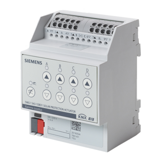
GAMMA instabus
Solar protection actuator 4/8 x 6 A
N 543D31, N 543D51
A6V11986596_en--_e
2022-04-27
The solar protection actuators are used to control shutters, roller shutters, awn-
ings, sunblinds or ventilation flap drives with up to AC 230 V.
●
End position detection by current sensing for automatic move time determination.
●
Direct operation for efficient installation displaying the moving direction and active
overrides via LED.
●
Maintenance-free terminals for connecting and looping through solid, stranded and
fine-stranded conductors. Every L-conductor connection feeds two channels.
Functions for configuration with ETS
●
Extensive control and override functions and status messages for each channel
●
On-site control of the drives
●
Direct moving to element or slat positions.
●
Automatic control of the drives with configurable behavior when the sun is shining
(sun tracking control)
●
Scene control for calling up and storing defined element positions
●
Safety functions through overrides in case of wind, rain, frost, moving blocks etc.
Smart Infrastructure
Building Products
Advertisement

Related Manuals for Siemens N 543D31


Summary of Contents for Siemens N 543D31
- Page 1 GAMMA instabus Solar protection actuator 4/8 x 6 A N 543D31, N 543D51 The solar protection actuators are used to control shutters, roller shutters, awn- ings, sunblinds or ventilation flap drives with up to AC 230 V. ● End position detection by current sensing for automatic move time determination.
- Page 2 Characteristics The solar protection actuators are used to control shutters, roller shutters, awnings, sun- blinds or ventilation flap drives with up to AC 230 V. It is used in building automation. Device control is conducted via KNX. Through the selection of various operating modes such as manual and automatic mode, solar protection is controlled both locally and centrally.
- Page 3 Resetting the device to factory settings A very long push of the programming button of more than 20 seconds resets the device to its factory settings. This is indicated by the programming LED flashing steadily for 8 seconds. All configuration settings are deleted. The building site function of the delivery state is re-ac- tivated.
- Page 4 Using 8-bit scene control, current solar protection or slat positions can be assigned to a scene and retrieved. Move to position 1/2, 3/4 (1-bit scene control) The function “move to position 1/2, 3/4” is particularly suitable to repeatedly move to pre- ferred element positions in combination with the 1-bit scene control.
- Page 5 For safe end position detection, the threshold value for electricity can be adjusted. The elec- tric current is evaluated in the process. Status messages Responses on element positions, such as dynamic element position, slat position, moves, moving directions, reaching the upper or lower end position are reported. In addition, re- sponses to the different overrides, current operating mode such as direct operation or auto- matic operation can be displayed.
- Page 6 Schematic design of a solar protection actuator channel The following scheme shows the function of a channel of the solar protection actuator using the “blind” function in a logical context. 8-bit Recall/store positions 1-bit Manual operation Solar protection via dimming Delay Automatic operation Delay...
- Page 7 Technical design Position and function of the connections and labeling Fig. 2: Position and function of the connections and labeling, Example: Solar protection actuator N 543D51, 8 x 6 A Pos. Element Function 1 Connection pins for KNX bus terminal Connect KNX bus. block, screwless 2 Label field Enter physical address.
- Page 8 Position and function of the operating and display elements Fig. 3: Control and display elements, example: Solar protection actuator N 543D51, 8 x 6 A Pos. Operating or display elements Function 1 Programming LED (red), Short push of button (< 2 s): Programming button ●...
- Page 9 Pos. Operating or display elements Function 6 Button: Stop/slat: Short press of button (< 1 s): “Up” move command of the channel ● Move command “Stop” or “Raise” ● Activate direct operation for the channel. Long push of button (> 1 s): ●...
- Page 10 Documents related the product, such as operating and installation instructions, application program description, product database, additional software and CE declarations can be downloaded from the following website: http://www.siemens.com/gamma-td Frequently asked questions For frequently asked questions about the product and their solutions, see: https://support.industry.siemens.com/cs/products?dtp=Faq&mfn=ps&lc=de-WW...
- Page 11 Commissioning Connecting motors to the relay contacts Fig. 4: Example: Solar protection actuator N 543D51, 8 x 6 A 0.5...2.5 mm² 2.5 mm² Connecting KNX Fig. 5: Example: Solar protection actuator N 543D51, 8 x 6 A 0.6…0.8 mm Smart Infrastructure A6V11986596_en--_e Building Products 2022-04-27...
- Page 12 Testing KNX 24 V DC type. SELV This test can be used to check whether the bus connection cable is connected with the cor- rect polarity and whether device is supplied with bus voltage. Fig. 6: Example: Solar protection actuator N 543D51, 8 x 6 A Operation in direct operation (A|B|C|D|E|F|G|H Un~ 230 V) Fig. 7: Example: Solar protection actuator N 543D51, 8 x 6 A Smart Infrastructure...
- Page 13 Function test of the installation This test can be used to check whether the motors have been connected correctly. Fig. 8: Example: Solar protection actuator N 543D51, 8 x 6 A Disposal The device is considered an electronic device for disposal in accordance with European Directive and may not be disposed of as domestic waste.
- Page 14 Technical data Type N 545D31 N 543D51 Power supply KNX bus voltage DC 24 V (DC 21...30 V) DC 24 V (DC 21...30 V) KNX bus current 15 mA 20 mA KNX power loss (internal 0.15 W 0.17 W consumption) Type N 545D31 N 543D51...
- Page 15 Type N 545D31 N 543D51 Mechanical data Fire load 5 MJ 9 MJ Environmental conditions Ambient temperature in operation -5 °C...+45 °C (23 °F...113 °F) Storage temperature -20 °C...+70 °C (-4 °F...158 °F) Transport temperature -25 °C...+70 °C (-13 °F...158 °F) Relative humidity 5 %...95 % (non-condensing)
- Page 16 Connection example The following connection example shows the connection of 6 AC motors for control (up/down or open/close) e.g. of solar protection, door, window or ventilation flaps via channels A, B, C, D, G and H. The transformers are used to detect the activation of electromagnetic and electronic end po- sition switches.
- Page 17 2. this device must accept any interference received, including interference that may cause undesired operation FCC Caution: Changes or modifications not expressly approved by Siemens Switzerland Ltd. could void the user’s authority to operate the equipment. United States representative https://new.siemens.com/us/en/products/buildingtechnologies/home.html Industry Canada statement This device complies with ISED’s license-exempt RSSs.
- Page 18 Issued by © Siemens Switzerland Ltd, 2022 Siemens Switzerland Ltd Technical specifications and availability subject to change without notice. Smart Infrastructure Global Headquarters Theilerstrasse 1a CH-6300 Zug +41 58 724 2424 www.siemens.com/buildingtechnologies Document ID A6V11986596_en--_e Edition 2022-04-27...