Hitachi SAMURAI Series Manual
Hide thumbs
Also See for SAMURAI Series:
- Service manual (137 pages) ,
- Service manual (174 pages) ,
- Service manual (140 pages)
Chapters
Table of Contents
Troubleshooting

Related Manuals for Hitachi SAMURAI Series


Summary of Contents for Hitachi SAMURAI Series
- Page 1 SAMURAI SERIES CONDENSERLESS WATER CHILLERS -SCREW TYPE- CLG2 Technical Catalogue Installation, operation and maintenance instructions. Design information. RCUE40CLG2 RCUE50CLG2 RCUE60CLG2 RCUE80CLG2 RCUE100CLG2 RCUE120CLG2...
- Page 3 Specifications in this manual are subject to change without notice in order that HITACHI may bring the latest innovations to their customers. Whilst every effort is made to ensure that all specifications are correct, printing errors are beyond Hitachi’s control; Hitachi cannot be held responsible for these errors.
- Page 5 Contents o n t e n t s Important Notice Features and Benefits Operation Instructions Components of chiller Preparation Initial Check Installation Test Running Controller Adjustment Self-Inspection Functions Control System Maintenance Troubleshooting General Specifications Drawings Model Selection Application Data Components Data TCGB0051 rev.0 - 09/2009...
-
Page 7: Table Of Contents
2.3. Control ..............................16 2.4. Heat Exchanger ............................17 2.5. Electronic Expansion Valve ........................18 3. Operation instructions.......................19 3.1. HITACHI condenserless Water Chiller Models: RCUE(40~120)CLG2 ............ 20 4. Components of chiller .......................21 4.1. Structure drawing ............................ 22 5. Preparation initial check ....................23 5.1. - Page 8 11.5. Winter shutdown ............................ 70 11.6. Spring start-up ............................70 11.7. Part replacement............................ 71 11.8. Refrigeration cycle ..........................71 11.9. Refrigerant cycle diagram of Hitachi condenserless Chiller (RCUE(40,50,60,80,100,120)CLG2 ....................72 11.10. Compressor removal..........................73 11.11. Safety and protection control ....................... 73 11.12.
- Page 9 Contents Technical Catalogue Unit code list ¡ NOTE: Please check by model name your condenserless type, its abbreviation and MODEL CODIFICATION reference number in this technical catalogue. CLG2 SERIES Unit Code Unit Code RCUE40CLG2 8E042072 RCUE80CLG2 8E082072 RCUE50CLG2 8E052072 RCUE100CLG2 8E102072 RCUE60CLG2...
-
Page 11: Important Notice
Technical Catalogue I m p o r t a n t n o t i c e HITACHI pursues a policy of continuing improvement in design and performance of Products. The right is therefore reserved to vary specifications without notice. -
Page 13: Features And Benefits
Features and Benefits Technical Catalogue F e a t u r e s a n d B e n e f i t s Contents 2. Features and benefits ................13 2.1. Chiller picture........................14 2.2. Compressor ........................14 2.3. Control ..........................16 2.4. Heat Exchanger .......................17 2.5. -
Page 14: Chiller Picture
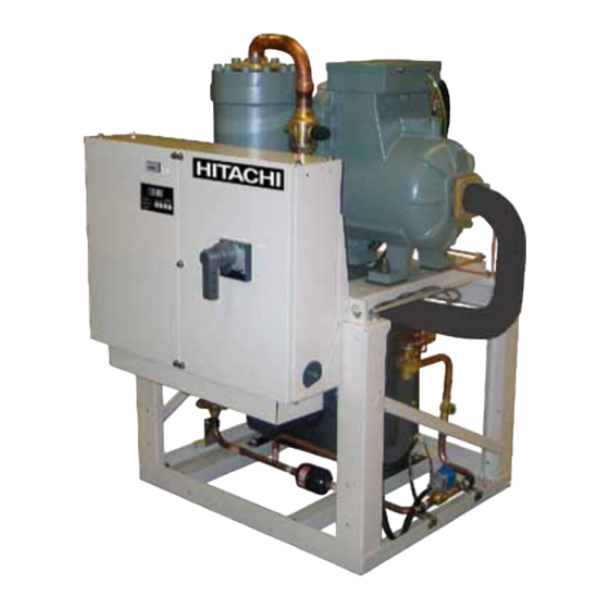
Features and Benefits Technical Catalogue 2.1. Chiller picture HITACHI is a world leader in technology and with continual research and product development, now offers a screw type Condenser less Chillers. A range of capacity are available from 120 kW to 360 kW. - Page 15 Suction Port CONTINUOUS CAPACITY CONTROL ¡ HITACHI´s Continuous Capacity Control system uses advanced electronic controls to position the infinitely variable slide valve within each compressor. This modulation allows exact load control and accurate chilled water temperature without the need for expensive inverters.
-
Page 16: Control
Features and Benefits Technical Catalogue Energy Saving ¡ Thanks to Continuous Capacity Control, 15~20% energy saving is possible compared with current step control systems due to the following: The cooling load can be more closely matched − Continuous Capacity Control takes advantage of high efficiency part load performance. −... -
Page 17: Heat Exchanger
Technical Catalogue Precise Temperature Control ¡ Combination of “Continuous Capacity Control Compressor” and “HITACHI´s unique electronic controls” enable the Chiller to control outlet water temperature precisely, independent of cooling load. This control benefits not only air-conditioning but also industrial process use. -
Page 18: Electronic Expansion Valve
Features and Benefits Technical Catalogue 2.5. Electronic Expansion Valve This unit are equipped with an electronic expansion valve to provide sophisticated control under any temperature condition. The electronic expansion valve provides reduced electrical power consumption compared to the classical system. TCGB0051 rev 0 - 09/2009... -
Page 19: Operation Instructions
Technical Catalogue O p e r a t i o n I n s t r u c t i o n s Contents 3. Operation instructions................19 3.1. HITACHI condenserless Water Chiller Models: RCUE(40~120)CLG2 ......20 TCGB0051 rev 0 - 09/2009... -
Page 20: Hitachi Condenserless Water Chiller Models: Rcue(40~120)Clg2
Operation Instructions Technical Catalogue 3.1. HITACHI condenserless Water Chiller Models: RCUE(40~120)CLG2 To Start the Unit. ¡ 1. Open the water inlet and outlet valves. 2. After assuring that all control switches have been cut OFF, and the “LOCAL/REMOTE” switch on the printed circuit board is in the “LOCAL”... -
Page 21: Components Of Chiller
Components of Chiller Technical Catalogue C o m p o n e n t s o f C h i l l e r Contents 4. Components of chiller ................21 4.1. Structure drawing ......................22 TCGB0051 rev 0 - 09/2009... -
Page 22: Structure Drawing
Components of Chiller Technical Catalogue 4.1. Structure drawing HITACHI Condenser less Water Chiller (Example of 1 Compressor Chiller) ¡ STRUCTURE DRAWING OF HITACHI CONDENSER LESS WATER CHILLER UNIT (Example: RCUE60CLG2) N° Name Compressor Water Cooler Electrical Box ... -
Page 23: Preparation Initial Check
Preparation initial check Technical Catalogue P r e p a r a t i o n I n i t i a l C h e c k Contents 5. Preparation initial check ................23 5.1. Initial check ........................24 5.2. Placing the unit ........................25 5.3. -
Page 24: Initial Check
Preparation initial check Technical Catalogue 5.1. Initial check Required Materials ¡ Measure and Architectural Information Regarding Installation Location Remote Condenser ¡ Check the capacity of the selected remote condenser. Installation Location ¡ Confirm that the final installation location is provided with convenient piping and wiring work. Strong water runoff should be avoided. -
Page 25: Placing The Unit
Preparation initial check Technical Catalogue 5.2. Placing the unit Service space ¡ DANGER - Do not install the unit outdoors. If installed outdoor, an electrical leakage will occur, since the unit has not been designed for dew protection - If leakage is detected, stop the unit and contact the installer or a service Chiller... -
Page 26: Centre Of Gravity
Preparation initial check Technical Catalogue 5.3. Centre of gravity Centre of Gravity Centre of Gravity Control Panel RCUE - CLG2 Model Location Weight Distribution (kg) Operating Weight (kg) 1250 1370 1450 Location of Centre of Gravity (mm) Dimension Dimension TCGB0051 rev 0 - 09/2009... -
Page 27: Service Space And Foundation
Preparation initial check Technical Catalogue 5.4. Service space and foundation RCUE 40, 50 60CLG2 RCUE 80, 100, 120CLG2 Detail of foundation (example: RCUE60CLG2) Nº Name Nº Name 4-Ø 26 (Mounting Holes) Steel Plate (1 mm) Electrical Box Concrete Bottom Frame Vibration proof Rubber Mat (1 mat per position) (option) Vibration proof Rubber Mat (4 positions) Washer... -
Page 28: Transportation By Rigging
The rigging angle shall be greater than 60° as shown. The weight of the unit is wires and the unit to indicated on the unit label. avoid damages. Lifting drawing of Hitachi condenser less water chiller unit (Example: RCUE60CLG2) N° Name ... -
Page 29: Installation
6.5.2. Evacuation and Refrigerant charge ..................37 6.6. BMS connection ......................37 6.6.1. System ..........................37 6.6.2. Signal ...........................38 6.6.3. Caution on use HARC70-CE1 (op) ..................38 6.6.4. Dimensional drawing and Specifications of Hitachi gateway (model HARC70-CE1/HARC70-CE1 0P) ................39 6.7.CSC-5S ..........................44 6.7.1. System ..........................44 6.7.2. Signal ...........................44 6.7.3. -
Page 30: Electrical Wiring
Installation Technical Catalogue 6.1. Electrical Wiring Tools and Instruments ¡ One set of wiring tools and electrical tester (clamp meter) Schedule Check ¡ DANGER: Switch OFF main interruptor (M.I) for any work inside Electrical Box. WARNING: - Confirm that the field-selected electrical components (main power switch, fuses, wires, conduit connections, wire terminals and others) are properly selected according to the “Electrical Data“... - Page 31 Installation Technical Catalogue N° Name In case of remote control operation this wire must be removed. S Phase Neutral Low Voltage / Remote Control Run/Stop Signal Alarm Signal Alarm Lamp Pump Interlock Pump Operation Remote Control Switch (RSW-A) (OPTION) 2 cycles 2 nd.
-
Page 32: Water Piping
To prevent freezing of the water, it is effective to operate the pumps even during shutdown period. HITACHI Chiller has the pump ON/OFF operation control (see Wiring Diagram) water from piping. Additionally, in a case where measures such as water draining are difficult, utlize antifreeze mixture of ethylene glycol type or propylenen glycol type. -
Page 33: Minimum Internal System Water Volume
Installation Technical Catalogue CAUTION: In case of connecting some units to the same water piping, design the water piping so that the water distribution to each unit is equal (refer to figure below) Imbalance of water distribution may cause a serious damage like a water freezing in the heat- exchanger. -
Page 34: Water Control
Installation Technical Catalogue 6.4. Water control CAUTION: When industrial water is applied for chilled water and condenser water, industrial water rarely causes deposits of scales or other foreign substances on equipment. However, well water or river water may in most cases contain suspended solid matter, organic matter, and scales in great quantities. - Page 35 Installation Technical Catalogue Maximum piping length and lift ¡ Maximum Equivalent Piping Maximum Difference in Heigh Length (m) Water Chiller is below Remote Condenser Water Chiller is above Remote Condenser CAUTION: Do not charge Oxygen, Acetylene or other flammable and poisonous gases into the refrigeration cycle when performing a leakage test or an airtight test.
- Page 36 Installation Technical Catalogue Refrigerant Piping Arrangement ¡ - Water chiller is below the remote condenser: Field-Supplied Liquid Loop Liquid Loop Remote Condenser Remote Condenser Oil Trap Oil Trap Maximum 25 meters At each At each 10 meters 10 meters Chiller Unit Oil Trap Oil Trap Receiver...
-
Page 37: Bms Connection
Chiller 3 Chiller 4 Chiller 1 One interface HARC70-CE1 can connect up to 4 Chillers from a remote place using H-Link connection (Hitachi communications protocol). Protocol used by HARC70-CE1 (OP) is LonWorks. Physical channel connection with interface is FTT-10ª TCGB0051 rev 0 - 09/2009... -
Page 38: Signal
Installation Technical Catalogue 6.6.2. Signal ON/OFF Chiller All HARC’S Control Operation Outlet Water Setting All HARC’S ON/OFF All HARC’S Chilled Water Outlet Setting All HARC’S Chilled Water Outlet Temperature All HARC’S Chilled Water Inlet Temperature. All HARC’S Alarm Codes All HARC’S Operation Status All HARC’S Discharge Pressure 1,2... -
Page 39: Dimensional Drawing And Specifications Of Hitachi Gateway (Model Harc70-Ce1/Harc70-Ce1 0P)
Monitoring Device corresponds with the condition of HARC in the interval of MaxSendTime . 14. It can’t be used with the except for “ stop signal of input terminal of Chiller unit “. 6.6.4. Dimensional drawing and Specifications of Hitachi gateway (model HARC70-CE1/HARC70-CE1 0P) Structural Drawing ¡... - Page 40 Ground Earth Wire (Field Supplied) Connection Wire Between LonWorks Signal Wire DC 5V (Field Supplied) Marking of Terminals ¡ CONTROL SYSTEM G/W HITACHI AC / AC / LON / H-LINK MCLR LON-SERV. LON H-LINK S202 S201 Mark Indication...
- Page 41 Installation Technical Catalogue Network Variables and Setting (HARC70-CE1) ¡ Chiller Water Condenser Air Heat SVNT LONMARK Name Type Description Contents Remarks Number Cooled less Cooled Pump Number SNVT No Byte 1: Value 0 (Fixed) nviChillerEnable_0 SNVT_switch On/Off Order Byte 2: State 0/1 = STOP/RUN nviCoolSetpt_0 SNVT_temp_p Cool Water Temperature Setting 2 Bytes: -2000 ~ 2500 = -20 ~ 25 ºC...
- Page 42 Installation Technical Catalogue Network Variables and Setting (HARC70-CE1 OP) ¡ Water Condenser Air Heat SVNT LONMARK Name Type Description Contents Remarks Cooled less Cooled Pump Number SNVT No Byte 1: Value 0 (Fixed) nviChillerEnable_0 SNVT_switch On/Off Order Byte 2: State 0/1 = STOP/RUN Cool Water Temperature nviCoolSetpt SNVT_temp_p...
- Page 43 Transceiver Using FTT-10A No warranty shall be applied for the control and operation of the upper “LonWorks” side. Warranty Hitachi’s liability shall cover only Hitachi Chillers, this gateway, and accessibility by “LonWorks” Transmitting Setting (On Chiller Control PCB) ¡ Operation Before shipment, No.
-
Page 44: Csc-5S
Installation Technical Catalogue 6.7.CSC-5S CSC-5S is a remote controller for Hitachi Water Chillers 6.7.1. System CSC-5S allows the individual control of a Chiller Unit as well as it allows a centralized and grouped controls of a maximum number of 8 chillers. -
Page 45: Installation Final Check
Installation Technical Catalogue 6.7.3. Caution on use of CSC-5S Follow strictly instructions of CSC-5S Installation Manual. This control requires power supply ~1 220-240 V. 6.7.4. Transmitting setting (on chiller control PCB) Operation Before shipment, No. 1 pin of DSW10 is set at ON side In case that Chiller Unit quantity in the same H-Link is 2 or more, set No. -
Page 47: Test Running
Test Running Technical Catalogue Te s t R u n n i n g Contents 7. Test running .....................47 7.1. Preparation ........................48 7.2. Test running procedure ....................48 7.3. Instructions after test running ..................48 TCGB0051 rev 0 - 09/2009... -
Page 48: Preparation
CAUTION: When the unit is wired according to the HITACHI standard wiring shown on the wiring label. Switch ON the main power switch, and energize the oil heater for 12 hours before start-up to sufficiently warm the oil. Each rotation direction of two rotors in the compressor is fixed so that a reversal phase protection device is equipped. -
Page 49: Controller Adjustment
Controller Adjustment Technical Catalogue C o n t r o l l e r A d j u s t m e n t Contents 8. Controller adjustment ................49 8.1. PCB Drawing ........................50 8.2. Control System ........................51 8.3. Controller Adjustment ......................51 TCGB0051 rev 0 - 09/2009... -
Page 50: Pcb Drawing
Controller Adjustment Technical Catalogue 8.1. PCB Drawing Cool PUSH 7 SEGMENTS Heat BUTTON SWITCH SWITCH POSITION Local Remote High Cut Check (Fan Stop for Checking) Mode Set Switch B (NOT AVAILABLE) Local/Remote Changeover Switch Chilled Water Temperature Setting (STANDARD: “Local”) (STANDARD: “+07”) ... -
Page 51: Control System
Controller Adjustment Technical Catalogue 8.2. Control System Electrical Operation Control advanced HITACHI Condenser less Chillers are as follows. Capacity Control ¡ All models are equipped with an unloading system for each compressor, in order to adjust the cooling capacity and to provide precise temperature control for the chilled water, coupled with electronic thermostats.. - Page 52 Controller Adjustment Technical Catalogue Neutral Zone Setting Switch = RSW8 ¡ = 2 degrees is standard. The RSW8 dial is already set at 3 (= 2 degrees). The figures at the RSW8 dial mean as follows: Figure Band (degree) Continuous Capacity Control Setting Switch = DSW5 ¡...
- Page 53 Controller Adjustment Technical Catalogue Temperature Band for Restart Setting Switch = 2 degree is standard. The figure 3 and 4 of the DSW5 switch are already set at figure 3 = ON side, 4 = OFF side. The locations at the figure 3 and 4 of the DSW5 mean as follows. Figure Location Band(degree)
- Page 54 Controller Adjustment Technical Catalogue Manual Set Switch A = DSW3 ¡ * Compressor Forcedly Stop Mode Setting Switch * Switches “DSW3-1” is for No.1 compressor, “DSW3-2” for No.2. If necessary to stop any compressors, turn these switches (DSW3-1, DSW3-2) to the OFF side, the compressors corresponding to these switches are turned to the OFF side will be stopped.
-
Page 55: Self-Inspection Functions
Self-Inspection Functions Technical Catalogue S e l f - I n s p e c t i o n f u n c t i o n s Contents 9. Self-Inspection functions .................55 9.1. Alarm Indication .......................56 9.2. Normal Indication......................57 9.3. -
Page 56: Alarm Indication
Self-Inspection Functions Technical Catalogue 9.1. Alarm Indication If the unit is operated under abnormal conditions, an alarm code (refer to the SEG.1 SEG.2 table below) is indicated and the “Alarm” LED lamp is lighted. 7 Segments on Function of 7-Segment Light Emitted Diode on Control Panel is as shown in Control Panel the table below. -
Page 57: Normal Indication
Self-Inspection Functions Technical Catalogue 9.2. Normal Indication If the unit is operated under a normal operation condition, the operation code (refer to the table below) is indicated on 7-Segment LED’s of the control panel. Code No.1 No.2 Content Cycle Cycle Power Supply, After Stoppage Cooling Operation Stoppage by Thermo-OFF or Retry by Alarm Cx-5x... - Page 58 Self-Inspection Functions Technical Catalogue Indication Mode of Alarm Occurrence Data ¡ The content of abnormal stoppage including activation of safety devices is memorised and indicated on the control panel Alarm Occurrence Data (Max.10 data) Example: In case of No.
- Page 59 Self-Inspection Functions Technical Catalogue ∆↓ ↑∇ Suction Gas Temperature (°C) ∆↓ ↑∇ Evaporating Temperature (°C) ∆↓ ↑∇ (N° 1 Cycle = -4°C) ...
- Page 60 Self-Inspection Functions Technical Catalogue Memory Data Indication in Alarm ¡ Data is indicated same as Checking Indication. In addition the checking data, below data is added. ∆↓ ↑∇ Evaporating Temperature (°C) ∆↓ ↑∇ Water Outlet Temperature (Cooler ...
- Page 61 Self-Inspection Functions Technical Catalogue 3) Press the check “ “ and “ ” switches simultaneously for more than 3 seconds. At the same time, the setting value shown on display is memorized and available. ⇔ . * The setting is changed to 9.5ºC. * Hot water temperature setting change is performed by same procedure mention above.
-
Page 63: Control System
Control System Technical Catalogue C o n t r o l S y s t e m Contents 10. Control system..................63 10.1. Standard operating sequence for RCUE40CLG2, RCUE50CLG2 and RCUE60CLG2 ................64 10.2. Standard operating sequence for RCUE80CLG2, RCUE100CLG2 and RCUE120CLG2 ................65 TCGB0051 rev 0 - 09/2009... -
Page 64: Standard Operating Sequence For Rcue40Clg2, Rcue50Clg2 And Rcue60Clg2
Control System Technical Catalogue 10.1. Standard operating sequence for RCUE40CLG2, RCUE50CLG2 and RCUE60CLG2 Control Stage Starting Control Capacity Control Safety Devices Shut Down Control Devices Main Power Switch Chilled Water Pump Condenser Water Pump Operation Switch (ON/OFF) Load Up Neutral Controller Load Down... -
Page 65: Standard Operating Sequence For Rcue80Clg2, Rcue100Clg2 And Rcue120Clg2
Control System Technical Catalogue 10.2. Standard operating sequence for RCUE80CLG2, RCUE100CLG2 and RCUE120CLG2 Control Stage Starting Control Capacity Control Safety Devices Shut Down Control Devices Main Power Switch Chilled Water Pump Condenser Water Pump Operation Switch (ON/ OFF) Load Controller Neutral Load Down... -
Page 67: Maintenance
11.5. Winter shutdown ......................70 11.6. Spring start-up .......................70 11.7. Part replacement ......................71 11.8. Refrigeration cycle ......................71 11.9. Refrigerant cycle diagram of Hitachi condenserless Chiller (RCUE(40,50,60,80,100,120)CLG2 ................72 11.10. Compressor removal ....................73 11.11. Safety and protection control ..................73 11.11.1. Safety and control device setting ..................74 11.12. -
Page 68: Components
The semi-hermetic screw compressor requires periodic maintenance, including explosion. replacement of parts. See the HITACHI Service Handbook for Screw Compressors, for Turn OFF the main details. switch when electrical... -
Page 69: Cleaning Method
Maintenance Technical Catalogue CAUTION: - Correctly select cleaning agent depending on scales in the plate type heat exchangers. The cleaning chemicals are different depending on fouling degree. - This plate type heat exchanger is made of stainless steel. Do not use a cleaning agent containing hydrochloric acid or fluorine compound. -
Page 70: Winter Shutdown
Maintenance Technical Catalogue 4. Waste Fluid - Stop the acid-resistant pump. - Put the waste fluid into the waste fluid tank. - Supply water into the cleaning tank and operate the pump for water cleaning. - Put the cleaning water into the waste fluid tank as same as the waste fluid. - Measure pH degree by using a pH test sheet and neutralize the waste fluid by gradually adding neutralizing agent. -
Page 71: Part Replacement
Maintenance Technical Catalogue 11.7. Part replacement Replacement of parts should be undertaken by ordering from the HITACHI Spare Parts List. CAUTION: Do not replace with spare parts which are not the equivalent. 11.8. Refrigeration cycle Strainer ¡ Check for clogging each time when the refrigeration cycle is opened. -
Page 72: Refrigerant Cycle Diagram Of Hitachi Condenserless Chiller (Rcue(40,50,60,80,100,120)Clg2
Maintenance Technical Catalogue 11.9. Refrigerant cycle diagram of Hitachi condenserless Chiller (RCUE(40,50,60,80,100,120)CLG2 Flange Connection Flare Connection Solder Connection Refrigerant Cycle Inlet Chilled Water Outlet Condenserless Field Supplied Chiller Name Name Compressor Water Cooler Check Valve Stop Valve (Option) Pressure Relief Valve... -
Page 73: Compressor Removal
(water-cooled) hours or 5 years. and 24,000 (air-cooled) hours or 3 years pass after installation, exchange the bearings of the compressor. For details, refer to the Service Handbook for HITACHI Screw Compressors. - For R407C refrigerant system, charge the refrigerant with liquid condition to avoid its composition change. -
Page 74: Safety And Control Device Setting
Maintenance Technical Catalogue 11.11.1. Safety and control device setting RCUE Model CLG2 For Compressor Manual reset, non-adjustable (one switch for each compressor motor ) High Pressure Switch Cut-Out 2,80 2,80 2,80 2,80 2,80 2,80 Low Pressure Switch Electronic control (Pressure Sensor) 0,05 0,05 0,05... -
Page 75: Normal Operating Pressure
Maintenance Technical Catalogue 11.12. Normal operating pressure Check to ensure that Chiller is operating within the working range as shown below, after at least 15 minutes operation. Low Pressure: The normal operating low pressure of the water chiller is indicated in the figure below; lower than 0.3 MPa indicates an abnormal condition. -
Page 76: Test Running And Maintenance Record
Maintenance Technical Catalogue 11.13. Test running and maintenance record MODEL: RCUE MFG. NO. COMPRESSOR MFG. NO. CUSTOMER’S NAME AND ADRESS: DATE: 1. Is there adequate water flow for the condenser (in case of water cooled type) and the water cooler? 2. -
Page 77: Daily Operating Records
Maintenance Technical Catalogue 11.14. Daily operating records Model: Date: Weather: Time of Operation Start: Stop. ( Ambient Temperature ºC ºC Room Temperature ºC Compressor High Pressure Pressure Voltage Current Condenser Water Inlet ºC Temperature: (Water-Cooled Type) Outlet ºC Condenser Air Temperature: (Air-Cooled Type) Chilled Water Inlet... -
Page 78: Servicing For R407C Refrigerant System
Maintenance Technical Catalogue 11.15. Servicing for R407C refrigerant system Refrigerant ¡ This R407C refrigerant is HFC type so that it has a feature of no ozone depletion. If it is mixed with another refrigerant, the serious changing would occur on its character. Therefore notice the following point when handling this refrigerant. -
Page 79: Troubleshooting
Troubleshooting Technical Catalogue T r o u b l e s h o o t i n g Contents 12. Troubleshooting ..................79 12.1. Troubleshooting table ....................80 TCGB0051 rev 0 - 09/2009... -
Page 80: Troubleshooting Table
Troubleshooting Technical Catalogue 12.1. Troubleshooting table The following table shows efficient checking procedures for trouble. Fault Possible Cause Check/Corrective Action Interlock Circuit for Chilled Water Pump is Open 1. Check the pump contactor. Repair or replace, if necessary. 2.Check for the faulty pump. Compressor Does Not Operate Electrical Protective Devices Are Tripped. - Page 81 Troubleshooting Technical Catalogue Fault Possible Cause Check/Corrective Action Too Much Water Flowing through the Condenser, 1.Adjust the water cock or the regulating valve. or Water is too Cold 2.Check the operation of cooling tower. Insufficient Refrigerant Charge 1.Add Refrigerant. Leakage from the Condenser Gas Outlet Valve 1.
-
Page 83: General Specifications
General Specifications Technical Catalogue G e n e r a l S p e c i f i c a t i o n s Contents 13. General specifications ................83 13.1. General data ........................84 13.2. Option line up ........................86 TCGB0051 rev 0 - 09/2009... -
Page 84: General Data
General Specifications Technical Catalogue 13.1. General data Model (R407C) RCUE40CLG2 RCUE50CLG2 RCUE60CLG2 Electrical power supply 3N~, 380-415V, 50Hz Cooling capacity Total power input 34.4 42.4 52.1 Outer dimension Height 1562 1562 1562 Width 1045 1045 1104 Depth Cabinet cooler Natural Gray Shipping weight Compressor type Semi-Hermetic Screw Type... - Page 85 General Specifications Technical Catalogue Model (R407C) RCUE80CLG2 RCUE100CLG2 RCUE120CLG2 Electrical power supply 3N~, 380-415V, 50Hz Cooling capacity Total power input 68.8 84.8 104.2 Outer dimension Height 1720 1720 1720 Width 1104 1104 1104 Depth 1471 1471 1471 Cabinet cooler Natural Gray Shipping weight 1,200 1,310...
-
Page 86: Option Line Up
General Specifications Technical Catalogue 13.2. Option line up Following table shows options: Specifications Standard Option Remarks Outlet Temperature: 0 ~ 4°C (Low1) Low water Outlet Temperature: -1 ~ -5°C (Low2) Temperature Outlet Temperature: - 6 ~ -10°C (Low3) ... -
Page 87: Drawings
Drawings Technical Catalogue D r a w i n g s Contents 14. Drawings....................87 14.1. Dimensional Drawings ....................88 14.1.1. RCUE40CLG2 ........................88 14.1.2. RCUE50CLG2 ........................88 14.1.3. RCUE60CLG2 ........................89 14.1.4. RCUE80CLG2 ........................89 14.1.5. RCUE100CLG2 ........................90 14.1.6. RCUE120CLG2 ........................90 14.2. Wiring Diagrams ......................91 14.2.1. -
Page 88: Dimensional Drawings
Drawings Technical Catalogue 14.1. Dimensional Drawings 14.1.1. RCUE40CLG2 Electrical Box Inlet for power supply wiring Inlet for control wiring Cooler Water Inlet 4x Lifting Holes Cooler Water Outlet 0 (welding connection) 54 (3B Victaulic connection) 14.1.2. RCUE50CLG2 Electrical Box Inlet for power supply wiiring Inlet for control wiring... -
Page 89: Rcue60Clg2
Drawings Technical Catalogue 14.1.3. RCUE60CLG2 Electrical Box Inlet for Power Supply Wiring Inlet for Control Wiring Cooler Water Inlet 4x Lifting Holes Cooler Water Outle 0 (welding connection) 54 (3B Victaulic connection) 14.1.4. RCUE80CLG2 Electrical Box Cooler Water Inlet 4x Lifting Holes Inlet for Inlet for Power... -
Page 90: Rcue100Clg2
Drawings Technical Catalogue 14.1.5. RCUE100CLG2 Electrical Box Cooler Water Inlet 4x Lifting Holes Inlet for Power Inlet for Control Wiring Supply Wiring 13 ( cooler, welding connection) Cooler Water Outlet 67 (cooler, 3B Victaulic connection) 14.1.6. RCUE120CLG2 Electrical Box Cooler Water Inlet 4x Lifting Holes... -
Page 91: Wiring Diagrams
Drawings Technical Catalogue 14.2. Wiring Diagrams 14.2.1. Power circuit for RCUE(40~120)CLG2 TCGB0051 rev 0 - 09/2009... -
Page 92: Control Circuit For Rcue40Clg2, Rcue50Clg2 And Rcue60Clg2
Drawings Technical Catalogue 14.2.2. Control circuit for RCUE40CLG2, RCUE50CLG2 and RCUE60CLG2 TCGB0051 rev 0 - 09/2009... -
Page 93: Control Circuit For Rcue80Clg2, Rcue100Clg2 And Rcue120Clg2
Drawings Technical Catalogue 14.2.3. Control circuit for RCUE80CLG2, RCUE100CLG2 and RCUE120CLG2 TCGB0051 rev 0 - 09/2009... -
Page 94: Main Printed Circuit Board
Drawings Technical Catalogue 14.2.4. Main printed circuit board TCGB0051 rev 0 - 09/2009... -
Page 95: Relays Printed Circuit Board
Drawings Technical Catalogue 14.2.5. Relays printed circuit board TCGB0051 rev 0 - 09/2009... -
Page 96: Customer Wiring
Drawings Technical Catalogue 14.2.6. Customer wiring NOTE: 1. All the setting must be performed before Power ON. 2. Remote / Local Change over Switch on Operation Switch must be set, to Remote. 3. Terminals 1 ~ n57 are for AC220-240V. Terminals A ~ D are for DC24V. Terminals E ~ F are H-link (Low signal). TCGB0051 rev 0 - 09/2009... -
Page 97: Parts List
Drawings Technical Catalogue 14.2.7. Parts list Mark Name Remark Mark Name Remark Compressor motor Solenoid valve for starting 11-n1 Main isolator Solenoid valve for load-down 12-n2 Solenoid valve for load-up Contactor for compressor motor 13-n3 Contactor for compressor motor (start Solenoid valve operation) s1-sn... -
Page 99: Model Selection
Model Selection Technical Catalogue M o d e l S e l e c t i o n Contents 15. Model selection..................99 15.1. Selection Example .......................100 15.2. Performance Table ......................101 15.3. Electrical Data ......................105 15.4. Sound Data........................106 TCGB0051 rev 0 - 09/2009... -
Page 100: Selection Example
Model Selection Technical Catalogue 15.1. Selection Example 1. Determine the system requirements Condensing Temperature: 40 °C Chilled Water Inlet Temperature: 12 °C Chilled Water Outlet Temperature: 7 °C Cooling Load: 300 kW Refrigerant: R407C 2. Select Model and Read the Performance. From the cooling capacity table, model RCUE100CLG2 can be selected with the following performance. -
Page 101: Performance Table
Model Selection Technical Catalogue 15.2. Performance Table RCUE40CLG2 RCUE50CLG2 RCUE60CLG2 CLOT CCAP CCAP CCAP 124,9 21,5 26,9 149,2 24,3 150,9 26,0 32,8 180,9 30,0 187,4 32,2 33,5 224,2 36,9 127,6 21,9 28,1 152,1 24,5 154,2 26,5 34,2 184,4 30,2 191,4 32,9 34,9 228,5... - Page 102 Model Selection Technical Catalogue Performance Table (cont.) RCUE40CLG2 RCUE50CLG2 RCUE60CLG2 CLOT CCAP CCAP CCAP 110,3 19,0 21,3 147,8 37,4 133,3 22,9 25,9 179,5 46,1 165,5 28,5 26,4 222,2 56,7 113,5 19,5 22,4 151,0 37,5 137,1 23,6 27,3 183,3 46,3 170,2 29,3 27,8 227,0...
- Page 103 Model Selection Technical Catalogue Performance Table (cont.) RCUE80CLG2 RCUE100CLG2 RCUE120CLG2 CLOT CCAP CCAP CCAP 249,8 43,0 23,6 298,5 48,7 301,9 51,9 33,8 361,8 60,0 374,7 64,5 50,9 448,4 73,7 255,2 43,9 24,5 304,2 49,1 308,3 53,0 35,1 368,8 60,5 382,8 65,8 53,0 457,1...
- Page 104 Model Selection Technical Catalogue Performance Table (cont.) RCUE80CLG2 RCUE100CLG2 RCUE120CLG2 CLOT CCAP CCAP CCAP 220,7 38,0 18,6 295,5 74,9 266,6 45,9 26,7 358,9 92,3 331,0 56,9 40,2 444,4 113,4 226,9 39,0 19,6 302,0 75,1 274,2 47,2 28,1 366,7 92,5 340,4 58,5 42,4 454,0...
-
Page 105: Electrical Data
Model Selection Technical Catalogue 15.3. Electrical Data Commpressor Applicable Maximum Motor Unit main power Instantaneous Unit Unit Model Voltage (V) Current Maximum (kW) (Hz) Maximum Minimum 59.4 34.4 RCUE40CLG2 56.4 34.4 54.4 34.4 73.2 42.4 RCUE50CLG2 69.5 42.4 67.0 42.4 90.0 52.1 RCUE60CLG2... -
Page 106: Sound Data
Model Selection Technical Catalogue 15.4. Sound Data Standard Models ¡ Sound Pressure Level (dB) Overall Frequency Band (Hz) Model (dBA) 1000 2000 4000 8000 RCUE40CLG2 RCUE50CLG2 RCUE60CLG2 RCUE80CLG2 RCUE100CLG2 RCUE120CLG2 Sound Power Level (dB) Overall Frequency Band (Hz) Model (dBA) 1000 2000 4000... -
Page 107: Application Data
Application Data Technical Catalogue A p p l i c a t i o n D a t a Contents 16. Application Data...................107 16.1. Working Range ......................108 16.2. Part Load Performance ....................108 16.3. Ethylene Glycol Application ..................110 TCGB0051 rev 0 - 09/2009... -
Page 108: Working Range
Humidity ≤ 50% (40 °C) Altitude ≤ 1000 m Minimum working range requeriments according to EN60204-1. In case of different working range conditions, ask conformity to HITACHI Distributor.) 16.2. Part Load Performance Model: RCUE40CLG2, RCUE50CLG2 and RCUE60CLG2 ¡ Compressor Load... - Page 109 Application Data Technical Catalogue Model: RCUE80CLG2, RCUE100CLG2 and RCUE120CLG2 ¡ Compressor Load Condensing Performance 7.5* 15~99% Full Temperature Capacity 55°C Input Capacity Input 50°C Capacity 45°C Input Capacity 40°C Input Capacity Input 35°C :Standard Condition (Condensing temperature: 45°C) (Cooler Water Inlet/Outlet: 12/7°C) ...
-
Page 110: Ethylene Glycol Application
Application Data Technical Catalogue 16.3. Ethylene Glycol Application Low ambient application ¡ Under the condition where the ambient temperature is low in winter, there is a case where the unit and piping will become damaged by freezing during the shutdown periods. To prevent freezing, it is effective to operate the pump. - Page 111 Application Data Technical Catalogue 2. Performance Condensing Temperature (°C) CAP IPT CAP IPT CAP IPT CAP IPT CAP IPT CAP IPT CAP IPT CAP IPT (wt%) (°C) (Kf) (Kp) ( % ) ( % ) ( % ) ( % ) ( % ) ( % ) ( % ) ( % ) ( % ) ( % ) ( % ) ( % ) ( % ) ( % ) ( % ) ( % ) 1,011 1,15 1,012...
-
Page 113: Components Data
Components Data Technical Catalogue C o m p o n e n t s D a t a Contents 17. Components data ................113 17.1. Compressor .........................114 17.2. Water Cooler .......................114 TCGB0051 rev 0 - 09/2009... -
Page 114: Compressor
Components Data Technical Catalogue 17.1. Compressor Model 40ASC-Z 50ASC-Z 60ASC-Z Type Semi-Hermetic Revolution 2880 Displacement 137.4 169.5 208.7 Capacity Control 100 ~ 15, 0 Pneumatic Pressure High Side Low Side Motor Type Special Squirrel Cage, Three-Phase Motor Starting Method Star-Delta Starting Nominal Output Poles Insulation... - Page 115 Components Data Technical Catalogue SINGLE TYPE COOLER DUAL TYPE COOLER Water In Water In Nº 1 Refrigerant Out Nº 2 Refrigerant Out Refrigerant Out Water Out Water Out Nº 1 Refrigerant In Nº 2 Refrigerant In Refrigerant In Water Water Plates Plates Nº...
- Page 118 -ken, Japan ISO 9001 Certified by JQA, Japan ISO 14001 Certified by JQA, Japan Hitachi Air Conditioning Products (M) Sdn. Bnd. Lot No. 10, Jalan Kemajan Bangi Industrial Estate 43650 Bandar Baru Bangi, Selangor Darul Ehsan, Malaysia Certification ISO 9001, Malaysia Certification ISO 14001, Malaysia TCGB0051 rev.0 - 09/2009 - Printed in Spain...