Siemens Cerberus PACE Manual
Hide thumbs
Also See for Cerberus PACE:
- Operating manual (42 pages) ,
- Mounting & installation (24 pages) ,
- Operation manual (57 pages)

Related Manuals for Siemens Cerberus PACE


Summary of Contents for Siemens Cerberus PACE
- Page 1 Cerberus PACE System Installation Mounting A6V10430579_en--_b Smart Infrastructure 2021-06-30...
- Page 2 All rights created by patent grant or registration of a utility model or design patent are reserved. Issued by: Siemens Switzerland Ltd. Smart Infrastructure Global Headquarters Theilerstrasse 1a CH-6300 Zug Tel. +41 58 724-2424 www.siemens.com/buildingtechnologies Edition: 2021-06-30 Document ID: A6V10430579_en--_b © Siemens Switzerland Ltd, 2018 2 | 173 A6V10430579_en--_b...
-
Page 3: Table Of Contents
Table of contents About this document .................. 19 Applicable documents ................... 22 Revision history ..................... 23 Safety ......................24 Safety notes ....................24 Safety regulations for the method of operation ..........25 Responsibility of the operator ................ 27 Standards and directives complied with ............28 Cyber security disclaimer ................ - Page 4 6.3.5 Connect 'PACE-Bus' (RS232) ............55 6.3.6 Connect logic control inputs ............56 6.3.7 Connect logic control outputs ............57 6.3.8 Audio path PC2003-A1 ..............58 6.3.9 Connect analog audio input ............59 6.3.10 Connect analog audio outputs ............60 6.3.11 Connect 100 V audio input ............
- Page 5 6.11.4 Connect 'PACE-Bus' (RS485) ............90 6.11.5 Logic control outputs ..............91 6.11.6 Logic control inputs ................ 91 6.12 System state indicator PT2004-A1 and PT2007-A1 ........92 6.12.1 Installation ..................92 6.12.2 Connect DC 24 V power supply............. 92 6.12.3 Connect inputs and outputs ............
- Page 6 6.23.1 Mounting ..................112 6.23.2 Installation ..................112 6.23.3 Configuration with the ID jumper ..........113 6.23.4 Connect DC 24 V power supply ........... 113 6.23.5 Connect 'PACE-Bus' (RS485) ............. 114 6.23.6 Logic control inputs ..............115 6.23.7 Analog control inputs ..............116 6.23.8 Logic control outputs ..............
- Page 7 7.2.6 Check the ID settings ..............134 7.2.7 Change the ID settings ..............135 Desk call station extension (Kaba) PTO2002-A1 and (Nordic) PTO2003-A1 ........................136 Fire brigade call station (AT) PT2002-A1 ............ 137 7.4.1 Mounting ..................137 7.4.2 Installation ..................137 7.4.3 Connect DC 24 V power supply...........
- Page 8 7.15 EOL3 (active) PCA2004-A1 ................ 169 7.15.1 Configuration with the ID switch ..........170 7.15.2 Installation of PCA2004-A1 ............171 7.16 Loop isolator (100V) PCA2005-A1 .............. 172 8 | 173 A6V10430579_en--_b...
- Page 9 Index of Figures Fig. 1: Example diagram of the 1-phase mains connection wiring ......33 Fig. 2: Example diagram of the 3-phase mains connection wiring ......34 Fig. 3: Wiring diagram for 1x battery sets..............35 Fig. 4: Wiring diagram for 2x battery sets..............36 Fig.
- Page 10 Fig. 29: PC2003-A1 'PACE-Bus' (RS232) connector ..........55 Fig. 30: PC2003-A1 logic control input connection ..........56 Fig. 31: PC2003-A1 logic control output connection ..........57 Fig. 32: PC2003-A1 audio path (one zone) ............58 Fig. 33: PC2003-A1 analog audio input connection ..........59 Fig.
- Page 11 Fig. 64: PV2007-A1 analog audio input and status output connector ..... 86 Fig. 65: PV2007-A1 100 V analog audio output connector ........87 Fig. 66: PT2010-A1 connector overview ..............90 Fig. 67: PT2004-A1 and PT2007-A1 connector overview ........92 Fig. 68: PN2001-A1 connector overview ..............96 Fig.
- Page 12 Fig. 100: PT2009-A1 connector rear view ............153 Fig. 101: PTO2006-A1 connector rear view ............156 Fig. 102: PTO2009-A1 connector overview ............158 Fig. 103: PNA2008-A1 connector overview ............160 Fig. 104: PNA2007-A1 connector overview ............162 Fig. 105: PCA2007-A1 mounting and installation connector ........ 164 Fig.
- Page 13 List of Tables Table 1: Digital audio matrices in- and output overview .......... 38 Table 2: PC2001-A1, PC2002-A1, PC2005-A1 and PC2006-A1 DC 24 V power supply connector ..................... 40 Table 3: PC2001-A1, PC2002-A1, PC2005-A1 and PC2006-A1 fault relay connector ......................... 41 Table 4: 'PACE-Bus' (RS485) connector - 'RS485' ..........
- Page 14 Table 32: PV2001-A1 100 V analog audio output connectors - 'Out A' and 'Out B' 74 Table 33: PV2002-A1 DC 24 V power supply connector ........76 Table 34: PV2002-A1 analog audio input and control connector - 'CH A' ..... 77 Table 35: PV2002-A1 analog audio input and control connector - 'CH B' .....
- Page 15 Table 67: PTO2008-A1 'PACE-Bus' (RS485) connector - 'X2' ......110 Table 68: PTO2008-A1 analog audio input connector - 'X3' ......... 110 Table 69: PTO2008-A1 analog audio output connector - 'X4' ....... 110 Table 70: PTO2008-A1 call station connectors - 'X5' and 'RJ1' ......111 Table 71: PTO2008-A1 call station connectors - 'RJ2' and 'RJ3' ......
- Page 16 Table 103: PTO2001-A1 DC 24 V power connector 1 - 'CN1' ......132 Table 104: PTO2001-A1 DC 24 V power connector 2 - '-CN2' ......132 Table 105: PTO2001-A1 RS232 connector 1 - 'CN4' ........... 133 Table 106: PTO2001-A1 RS232 connector 2 - 'CN3' ........... 133 Table 107: Connect PTO2002-A1 or PTO2003-A1 to PT2001-A1 ......
- Page 17 Table 138: PCA2008-A1 microphone input connectors - 'CN1' to 'CN4' ....166 Table 139: PCA2008-A1 microphone sum output connector - 'CN5' ....166 Table 140: PCA2008-A1 fault relay output connector - 'CN6' ....... 166 Table 141: PT2006-A1 connector - 'X1' ..............167 Table 142: PCA2004-A1 EOL3 ID switch..............
-
Page 19: About This Document
Should you require another copy of this document, please contact the Customer Support Center, phone +49 89 9221-8000. Goal and purpose This document describes how to mount and install a Cerberus PACE network- based voice alarm and announcement system for the following tasks: ●... - Page 20 About this document Applicable documents Target group Activity Qualification ● ● System owner According to EN 50110-1, 'This person can be the owner, 'nominated person with the overall employer, proprietor or a delegated responsibility to ensure the safe person.' operation of the electrical ●...
- Page 21 About this document Applicable documents ID code Examples ID_languageCOUNTRY_ modification index A6V10215123_deDE_a -- = multilingual or international A6V10215123_en--_a A6V10315123_----_a Date format The date format in the document corresponds to the recommendation of international standard ISO 8601 (format YYYY-MM-DD). Presentation conventions Text markups Special text markups are used as follows in this document: ⊳...
-
Page 22: Applicable Documents
About this document Applicable documents 1.1 Applicable documents You will find more information on the Cerberus PACE system and its components in the following documents: Title Document ID IT security policies Cerberus PACE – IT security policies A6V11439692 System documentation Cerberus PACE –... -
Page 23: Revision History
'd' instead of 'a' if the reference document is already this version. The table below shows this document's revision history: Version Edition date Brief description 2021-06-30 Added mounting and installation information for most of the Cerberus PACE Modular components. 2018-06-08 First edition A6V10430579_en--_b... -
Page 24: Safety
Safety Safety notes 2 Safety 2.1 Safety notes The safety notices must be observed in order to protect people and property. The safety notices in this document contain the following elements: ● Symbol for danger ● Signal word ● Nature and origin of the danger ●... -
Page 25: Safety Regulations For The Method Of Operation
2.2 Safety regulations for the method of operation National standards, regulations and legislation Siemens products are developed and produced in compliance with the relevant European and international safety standards. Should additional national or local safety standards or legislation concerning the planning, mounting, installation,... - Page 26 Modifications to the system design and the products Modifications to the system and to individual products may lead to faults, malfunctioning and safety risks. Written confirmation must be obtained from Siemens and the corresponding safety bodies for modifications or additions. Modules and spare parts ●...
-
Page 27: Responsibility Of The Operator
Disregard of the safety regulations Before they are delivered, Siemens products are tested to ensure they function correctly when used properly. Siemens disclaims all liability for damage or injuries caused by the incorrect application of the instructions or the disregard of danger warnings contained in the documentation. -
Page 28: Standards And Directives Complied With
Safety Standards and directives complied with 2.4 Standards and directives complied with A list of the standards and directives complied with is available from your Siemens contact. 2.5 Cyber security disclaimer Siemens provides a portfolio of products, solutions, systems and services that includes security functions that support the secure operation of plants, systems, machines and networks. -
Page 29: Preparatory Work
Preparatory work Installation site 3 Preparatory work This chapter contains all the instructions that must be carried out or ensured by the customer before the system is actually mounted and installed. 3.1 Installation site General guidelines ● The housings used must conform to the types listed in the documentation and to at least protection category IP 30, in accordance with EN 60529:1991 or EN 60529:1991/A2:2000. -
Page 30: Electrical Supply Lines
Preparatory work Electrical supply lines 3.3 Electrical supply lines General guidelines 1. Read the safety instructions for electrical installations in Safety regulations for the method of operation. 2. Batteries must only be inserted and connected in the housing by authorized specialist personnel. -
Page 31: Mounting/Installation Of Cabinets
Mounting/installation of cabinets Mounting the 19" pedestal cabinet 4 Mounting/installation of cabinets 4.1 Mounting the 19" pedestal cabinet WARNING Severe accidents due to tipping ● Secure the cabinet mechanically by fixing it to the floor or to the wall. ● Do not open the swivel frame of the 19"... -
Page 32: Wiring The Mains Supply Line
Mounting/installation of cabinets Wiring the mains supply line 4.2 Wiring the mains supply line WARNING Electrical voltage Electric shock ● Work on electrical installations may only be carried out by qualified electricians or by instructed persons working under the guidance and supervision of a qualified electrician, in accordance with the electrotechnical regulations. -
Page 33: 1-Phase Mains Connection
Mounting/installation of cabinets Wiring the mains supply line 4.2.1 1-phase mains connection Terminal block 2 Terminal block 1 glb/gn Fig. 1: Example diagram of the 1-phase mains connection wiring Cable ducts on left side panel Power socket for notebook Terminal block 2, line distributor Terminal block 1, line distributor and line supply Mains connection cable, 3-core Terminal designation... -
Page 34: 3-Phase Mains Connection
Mounting/installation of cabinets Wiring the mains supply line 4.2.2 3-phase mains connection Terminal block glb/gn Fig. 2: Example diagram of the 3-phase mains connection wiring Cable ducts on left side panel Power socket for notebook Terminal block for line distributor and line supply Power supply cable, 5-core Terminal designation Connection... -
Page 35: Power Supply And Batteries
Power supply and batteries Power supply PP2003 5 Power supply and batteries Depending on the design and space, a maximum of 2 battery blocks can be installed in the pedestal cabinet and buffered via the power supply. General guidelines Do not connect the batteries after installation; instead, connect them immediately before commissioning starts. -
Page 36: Fig. 4: Wiring Diagram For 2X Battery Sets
Power supply and batteries Power supply PP2003 Fig. 4: Wiring diagram for 2x battery sets Battery separator/fuse, positive conductor Battery fuse Battery separator/fuse, equalizing charge conductor BAT1 Battery block 1 BAT2 Battery block 2 Power unit terminal Connection Conductor color Bat 24 V 1/+ Battery +24 V Battery –... -
Page 37: External Power Supply Pp2004
Power supply and batteries External power supply PP2004 5.2 External power supply PP2004 The external power supply 'Merawex ZSP135 DR-7A-3 40 Ah' PP2004-A1 is a wall-mounted power supply with batteries and the following connections: ● 230 V mains connection via power supply terminals ●... -
Page 38: Install Internal Components
Install internal components Digital audio matrices 6 Install internal components The internal components are mounted and installed in the Cerberus PACE cabinet. 6.1 Digital audio matrices The digital audio matrices are the master of the audio routing in the system and the system controlling. -
Page 39: Digital Audio Matrices Pc2001-A1, Pc2002-A1, Pc2005-A1 And Pc2006-A1
Install internal components Digital audio matrices PC2001-A1, PC2002-A1, PC2005-A1 and PC2006-A1 6.2 Digital audio matrices PC2001-A1, PC2002-A1, PC2005-A1 and PC2006-A1 The digital audio matrices are the master of the audio routing in the system and the system controlling. The 4 digital audio matrices below are described in this chapter: ●... -
Page 40: Connect Dc 24 V Power Supply
Ethernet Switch' PN2005-A1 to extend the amount of 'PACE-Net' Ethernet connections. The Ethernet switches are used to connect further Cerberus PACE modular or Cerberus PACE Compact systems, 'PACE-Net' call stations or a PC with the configuration tool 'PACE-Design' installed. ETH B ETH A Fig. -
Page 41: Connect General Fault Relay
Install internal components Digital audio matrices PC2001-A1, PC2002-A1, PC2005-A1 and PC2006-A1 6.2.3 Connect general fault relay The digital audio matrices provide one general fault relay output. Fault Fig. 10: PC2001-A1, PC2002-A1, PC2005-A1 and PC2006-A1 fault relay connector General fault relay connector Designator Connection Connected to C if fault occurs (relay... -
Page 42: Connect 'Pace-Bus' (Rs485)
Install internal components Digital audio matrices PC2001-A1, PC2002-A1, PC2005-A1 and PC2006-A1 6.2.4 Connect 'PACE-Bus' (RS485) The digital audio matrices provide one 'PACE-Bus' (RS485) connector 'RS485' at the rear of the housing. This connector can be used to connect the 'PACE-Bus' (RS485) input and output expansion modules and the 'PACE-Bus' (RS485) call stations. -
Page 43: Connect 'Pace-Bus' (Rs232)
Install internal components Digital audio matrices PC2001-A1, PC2002-A1, PC2005-A1 and PC2006-A1 It ensures that a short on the external wiring does not influence the internal function of the cabinet. 6.2.5 Connect 'PACE-Bus' (RS232) The digital audio matrices provide one 'PACE-Bus' (RS232) connector 'RS232' at the rear of the housing. -
Page 44: Connect Analog Control Inputs
Install internal components Digital audio matrices PC2001-A1, PC2002-A1, PC2005-A1 and PC2006-A1 6.2.6 Connect analog control inputs The digital audio matrices provide one connector with 8 analog control inputs at the rear of the housing. The analog control inputs are used as a local gain control or as a control for audio output volume. -
Page 45: Connect Logic Control Inputs
Install internal components Digital audio matrices PC2001-A1, PC2002-A1, PC2005-A1 and PC2006-A1 6.2.7 Connect logic control inputs The digital audio matrices provide one connector with 8 logic control inputs at the rear of the housing. The logic control inputs are used to get information and controls from the connected components. -
Page 46: Connect Logic Control Outputs
Install internal components Digital audio matrices PC2001-A1, PC2002-A1, PC2005-A1 and PC2006-A1 6.2.8 Connect logic control outputs The digital audio matrices provide one connector with 8 logic control outputs at the rear of the housing. The logic control outputs are used to activate LEDs or communicate a status change of the system. -
Page 47: Connect Analog Audio Inputs
Install internal components Digital audio matrices PC2001-A1, PC2002-A1, PC2005-A1 and PC2006-A1 6.2.9 Connect analog audio inputs The digital audio matrices PC2001-A1 and PC2005-A1 provide 4 XLR connectors ('IN1' to 'IN4') with 4 balanced analog audio inputs at the rear of the housing. The analog audio inputs are used to connect analog audio sources like microphones or audio media players to the digital audio matrix. -
Page 48: Connect Analog Audio Outputs
Install internal components Digital audio matrices PC2001-A1, PC2002-A1, PC2005-A1 and PC2006-A1 6.2.10 Connect analog audio outputs The digital audio matrices provide 4 XLR connectors ('OUT1' to 'OUT4') with 4 balanced analog audio outputs at the rear of the housing. The analog audio outputs are used to connect analog audio components like small speakers or audio amplifiers to the digital audio matrix. -
Page 49: Connect 100 V Audio Input And Speaker Lines
Install internal components Digital audio matrices PC2001-A1, PC2002-A1, PC2005-A1 and PC2006-A1 6.2.11 Connect 100 V audio input and speaker lines The digital audio matrices PC2001-A1 and PC2002-A1 provide 2 connectors ('Zone 1-2' and 'Zone 3-4') with 100 V audio inputs and 100 V audio outputs at the rear of the housing. -
Page 50: Audio Path Pc2001-A1 And Pc2002-A1
Install internal components Digital audio matrices PC2001-A1, PC2002-A1, PC2005-A1 and PC2006-A1 The speaker line can be configured in stub line configuration. In stub configuration the speaker lines can be supervised with 'EOL3 (active)' PCA2004-A1 or with impedance supervision. The digital audio matrices PC2001-A1 and PC2002-A1 do not support speaker lines in loop configuration with 'Loop isolator (100V)' PCA2005-A1. -
Page 51: Audio Path Pc2005-A1 And Pc2006-A1
Install internal components Digital audio matrices PC2001-A1, PC2002-A1, PC2005-A1 and PC2006-A1 6.2.13 Audio path PC2005-A1 and PC2006-A1 These digital audio matrices do not support amplifier supervision and speaker line detection: ● 'Digital audio matrix no supervision (4/4/0)', PC2005-A1 ● 'Digital audio matrix no supervision (0/4/0)', PC2006-A1 NOTICE This configuration does not meet the EN 54-16 requirements. -
Page 52: Digital Audio Matrix Pc2003-A1
Install internal components Digital audio matrix PC2003-A1 6.3 Digital audio matrix PC2003-A1 The digital audio matrix PC2003-A1 is the master of the audio routing in the system and the system controlling. The digital audio matrix provides a micro SD card slot. The PC2003-A1 features the following inputs and outputs: Network Power supply... -
Page 53: Connect 'Pace-Net' Ethernet
Ethernet Switch' PN2005-A1 to extend the amount of 'PACE-Net' Ethernet connections. The Ethernet switches are used to connect further Cerberus PACE modular or Cerberus PACE Compact systems, 'PACE-Net' call stations or a PC with the configuration tool 'PACE-Design' installed. ETH B ETH A Fig. -
Page 54: Connect 'Pace-Bus' (Rs485)
Install internal components Digital audio matrix PC2003-A1 6.3.4 Connect 'PACE-Bus' (RS485) The digital audio matrix PC2003-A1 provides one 'PACE-Bus' (RS485) connector ('RS485/RS232') at the rear of the housing. This connector can be used to connect the 'PACE-Bus' (RS485) input and output expansion modules and the 'PACE-Bus' (RS485) call stations. -
Page 55: Connect 'Pace-Bus' (Rs232)
Install internal components Digital audio matrix PC2003-A1 6.3.5 Connect 'PACE-Bus' (RS232) The digital audio matrix PC2003-A1 provides one 'PACE-Bus' (RS232) connector ('RS485/RS232') at the rear of the housing. This connector can be used to connect the 'PACE-Bus' (RS232) option modules and for diagnosis. NOTICE Use either 'PACE-Bus' (RS485 or RS232) The digital audio matrices do not allow to use the RS485 and the RS232 at the... -
Page 56: Connect Logic Control Inputs
Install internal components Digital audio matrix PC2003-A1 6.3.6 Connect logic control inputs The digital audio matrix PC2003-A1 provides one connector with 8 logic control inputs at the rear of the housing. The logic control inputs are used to get information and controls from the connected components. -
Page 57: Connect Logic Control Outputs
Install internal components Digital audio matrix PC2003-A1 6.3.7 Connect logic control outputs The digital audio matrix PC2003-A1 provides one connector with 8 logic control outputs at the rear of the housing. The logic control outputs are used to activate LEDs or communicate a status change of the system. -
Page 58: Audio Path Pc2003-A1
Install internal components Digital audio matrix PC2003-A1 6.3.8 Audio path PC2003-A1 The digital audio matrix PC2003-A1 features 4 independent audio channels and a 100 V speaker line output matrix with 4 amplifier inputs to 16 speaker line outputs and inputs for up to 4 backup amplifiers. It provides amplifier supervision and speaker line detection: Line 100V... -
Page 59: Connect Analog Audio Input
Install internal components Digital audio matrix PC2003-A1 6.3.9 Connect analog audio input The digital audio matrix PC2003-A1provides 4 connectors ('IN1' to 'IN4') with 4 balanced analog audio inputs at the rear of the housing. The analog audio inputs are used to connect analog audio sources like microphones or audio media players to the digital audio matrix. -
Page 60: Connect Analog Audio Outputs
Install internal components Digital audio matrix PC2003-A1 6.3.10 Connect analog audio outputs The digital audio matrix PC2003-A1 provides 4 connectors ('OUT1' to 'OUT4') with 4 balanced analog audio outputs at the rear of the housing. The analog audio outputs are used to connect analog audio components like small speakers or audio amplifiers to the digital audio matrix. -
Page 61: Connect 100 V Audio Input
Install internal components Digital audio matrix PC2003-A1 6.3.11 Connect 100 V audio input The digital audio matrix PC2003-A1 provides 4x 100 V audio input connectors ('A1' to 'A4') at the rear of the housing. Fig. 35: PC2003-A1 100 V audio input connection 100 V audio input connectors - 'A1' to 'A4' Description Remark... -
Page 62: Connect 100 V Audio Backup Input
Install internal components Digital audio matrix PC2003-A1 6.3.13 Connect 100 V audio backup input The digital audio matrix PC2003-A1 provides 4x 100 V audio backup inputs connectors ('B1' to 'B4') at the rear of the housing. The PC2003-A1 switches to the backup amplifier in case of an amplifier fault. Fig. -
Page 63: Backup Concept
Install internal components Digital audio matrix PC2003-A1 6.3.14 Backup concept In case of an amplifier fault, a backup amplifier takes over its role and ensures that a message will still be played to the speaker lines. Matrix PC2003 Control Logic Amplifier 1-4 Amplifier 100V... -
Page 64: Backup With A Free Analog Output
Install internal components Digital audio matrix PC2003-A1 6.3.15 Backup with a free analog output If not all analog audio outputs of PC2003-A1 are used, the free one can be used as an analog audio input for the backup amplifier. Matrix Matrix PC2003 Control... -
Page 65: Backup With An Additional Digital Audio Matrix
Install internal components Digital audio matrix PC2003-A1 6.3.16 Backup with an additional digital audio matrix If all analog audio outputs of PC2003-A1 are used or a one-to-one for 3 or 4 amplifiers are required, an additional digital audio matrix can be used to feed the backup amplifier. -
Page 66: Backup With 'Backup Extension Pc2003' Pca2014-A1
Install internal components Digital audio matrix PC2003-A1 6.3.17 Backup with 'Backup extension PC2003' PCA2014-A1 If all analog audio outputs of PC2003-A1 are used and only one backup amplifier is required, the 'Backup extension PC2003' PCA2014-A1 can be used. The 'Backup extension PC2003' PCA2014-A1 is mounted directly on the analog audio outputs of the PC2003-A1. -
Page 67: Fig. 42: Pc2003-A1 Backup With Pca2014-A1
Install internal components Digital audio matrix PC2003-A1 Matrix Matrix PC2003 Control PC2003 PCA2014 Logic Amplifier Amplifier 1 Input OUT1 Amplifier 2 OUT2 Amplifier 3 OUT3 Amplifier supervision Amplifier 4 OUT4 Backup switch Backup Input Logic Backup Output Amplifier 1 Logic Output Audio Fig. -
Page 68: Use Control Inputs And Outputs
Install internal components Use control inputs and outputs 6.4 Use control inputs and outputs 6.4.1 Use analog control inputs The analog control inputs measure the voltage between GND and DC 10 V. Fig. 43: Use of analog control inputs A variable linear resistor 10 k potentiometer with at least 0.05 W (1/20 W) is required for this function. -
Page 69: Use Logic Control Inputs
Install internal components Use control inputs and outputs 6.4.3 Use logic control inputs Fig. 45: Use of logic control inputs An electrically isolated switch is required for this function. The switch is connected between the 10 V and a logic control input. A6V10430579_en--_b 69 | 173... -
Page 70: Use Logic Control Outputs
Install internal components Use control inputs and outputs 6.4.4 Use logic control outputs The connected components can be powered with the internal 10 V with the connected component connected to a logic output. Fig. 46: Wiring diagram for open collector logic control outputs with 10 V If the connected components require a different voltage, these components can be powered with an external power source. -
Page 71: Power Amplifier
6.5 Power amplifier Power amplifiers PV200x amplify low-level audio signals to 100 V speaker line voltage. The amplifiers use state-of-the art digital technology for maximum effectiveness. The Cerberus PACE portfolio includes these 4 components: ● 'Power amplifier (2x250W)', PV2001-A1 ●... -
Page 72: Power Amplifier (2X250W) Pv2001-A1
Install internal components Power amplifier (2x250W) PV2001-A1 6.6 Power amplifier (2x250W) PV2001-A1 The 'Power amplifier (2x250W)' PV2001-A1 comes with 2 independent audio amplifiers. Both amplify low-level audio signals to 100 V or 50 V speaker line voltage with an output power of 250 W. The 2x 50 V power outputs can be bridged to 1x 500 W (@ 100 V) 230V Channel A... -
Page 73: Connect Analog Audio Inputs And Controls
Install internal components Power amplifier (2x250W) PV2001-A1 6.6.3 Connect analog audio inputs and controls The 'Power amplifier (2x250W)' PV2001-A1 provides two connectors ('CH A' and 'CH B') to connect analog audio inputs and control inputs and outputs. CH A CH B Fig. -
Page 74: Connect 100 V Analog Audio Output
Install internal components Power amplifier (2x250W) PV2001-A1 Description Remark CH B OK Relay output channel B ok, open: fault CH B OK Relay output channel B ok, open: fault 230 V OK Relay output 230 V ok, open: fault 230 V OK Relay output 230 V ok, open: fault Table 31: PV2001-A1 analog audio input and control connector - 'CH B' 6.6.4 Connect 100 V analog audio output... -
Page 75: Use Pv2001-A1 In Bridged Mode 500 W
Install internal components Power amplifier (2x250W) PV2001-A1 6.6.5 Use PV2001-A1 in bridged mode 500 W The 'Power amplifier (2x250W)' PV2001-A1 can be used in the bridged mode with an output power of 500 W. ● Analog audio input: Bridge in parallel the channel A with channel B analog audio inputs 1 ('A IN 1' AND 'B IN 1') If the analog audio input shall be switched between input 1 and input 2, then also... -
Page 76: Power Amplifier (2X500W) Pv2002-A1
Install internal components Power amplifier (2x500W) PV2002-A1 6.7 Power amplifier (2x500W) PV2002-A1 The 'Power amplifier (2x500W)' PV2002-A1 comes with 2 independent audio amplifiers. Both amplify low-level audio signals to 100 V speaker line voltage with an output power of 500 W. It is prohibited to use the outputs in the bridged mode. -
Page 77: Connect Analog Audio Inputs And Controls
Install internal components Power amplifier (2x500W) PV2002-A1 6.7.3 Connect analog audio inputs and controls The 'Power amplifier (2x500W)' PV2002-A1 provides two connectors 'CH A' and 'CH B' to connect analog audio inputs and control inputs and outputs. CH A CH B Fig. -
Page 78: Connect 100 V Analog Audio Output
Install internal components Power amplifier (2x500W) PV2002-A1 Description Remark CH B OK Relay output channel B ok, open: fault CH B OK Relay output channel B ok, open: fault 230 V OK Relay output 230 V ok, open: fault 230 V OK Relay output 230 V ok, open: fault Table 35: PV2002-A1 analog audio input and control connector - 'CH B' 6.7.4 Connect 100 V analog audio output... -
Page 79: Power Amplifier (4X150W) Pv2003-A1
Install internal components Power amplifier (4x150W) PV2003-A1 6.8 Power amplifier (4x150W) PV2003-A1 The 'Power amplifier (4x150W)' PV2003-A1 comes with 4 independent audio amplifiers. All amplify low-level audio signals to 100 V or 50 V speaker line voltage with an output power of 150 W. The 50 V power outputs can be bridged to 2x 300 W (@ 100 V) 230V Mains... -
Page 80: Connect Analog Audio Inputs
Install internal components Power amplifier (4x150W) PV2003-A1 6.8.3 Connect analog audio inputs The 'Power amplifier (4x150W)' PV2003-A1 provide two connectors ('CH A/B' and 'CH C/D') to connect analog audio input and control the bridge mode. Fig. 59: PV2003-A1 analog audio input and bridge mode connectors Analog audio input and bridge mode connector - 'CH A/B' Description Remark... -
Page 81: Table 39: Pv2003-A1 Analog Audio Input And Bridge Mode Connector - 'Ch C/D
Install internal components Power amplifier (4x150W) PV2003-A1 Description Remark C/D IN + Br. Bridged channel C/D analog audio input + Bridged channel C/D GND reference C/D IN - Br. Bridged channel C/D analog audio input - Bridge C/D active Bridge C/D active: connected to pin 12 Bridge C/D active Bridge C/D active: connected to pin 11 Table 39: PV2003-A1 analog audio input and bridge mode connector - 'CH C/D'... -
Page 82: Connect Status Output Relays And Amplifier Activation
Install internal components Power amplifier (4x150W) PV2003-A1 6.8.4 Connect status output relays and amplifier activation The 'Power amplifier (4x150W)' PV2003-A1 provides one connect ('Control') to report status of the amplifier and to activate the amplifier. Link 1 Link 2 Fig. 60: PV2003-A1 status output relays and amplifier activation connector Status output and activation connector - 'Control' Description Remark... -
Page 83: Connect Delay Link
Install internal components Power amplifier (4x150W) PV2003-A1 6.8.5 Connect delay link In a cabinet with multiple PV2003-A1, these can be started with a delay to protect the mains power supply from current inrush during power up by the amplifiers. Connect link 1 socket to the next amplifier socket link 2 and so on with a standard copper Ethernet cable (CAT5). -
Page 84: Use Pv2003-A1 In Bridged Mode 2X300W
Install internal components Power amplifier (4x150W) PV2003-A1 6.8.7 Use PV2003-A1 in bridged mode 2x300W The 'Power amplifier (4x150W)' PV2003-A1 can be used in the bridged mode with an output power of 2x 300 W. 1. Analog audio input: Use the bridge mode analog audio inputs (pin 8 to pin 10) on both connectors ('CH A/B' and 'CH C/D') 2. -
Page 85: Power Amplifier (1X250W) Pv2007-A1
Install internal components Power amplifier (1x250W) PV2007-A1 6.9 Power amplifier (1x250W) PV2007-A1 The 'Power amplifier (1x250W)' PV2007-A1 comes with one audio amplifier. It amplifies low-level audio signals to 100 V or 50 V speaker line voltage with an output power of 250 W. 230V Channel A Mains... -
Page 86: Connect Analog Audio Inputs And Controls
Install internal components Power amplifier (1x250W) PV2007-A1 6.9.3 Connect analog audio inputs and controls The 'Power amplifier (1x250W)' PV2007-A1 provides one connector ('CH A') to connect analog audio inputs and status outputs. CH A Fig. 64: PV2007-A1 analog audio input and status output connector Analog audio input and status output connector - 'CH A' Description Remark... -
Page 87: Connect 100 V Analog Audio Output
Install internal components Power amplifier (1x250W) PV2007-A1 6.9.4 Connect 100 V analog audio output WARNING Voltages of up to AC 100 V at the 100 V analog audio output terminals Contact with live parts can lead to electric shock and may be fatal! ●... -
Page 88: Operating Terminals
Install internal components Operating terminals 6.10 Operating terminals The operating terminals PT200x display the operating and fault status of the system and provide buttons to control it. The Cerberus PACE Modular system includes these 4 components: ● 'System state indicator (19")', PT2004-A1 ●... -
Page 89: System Operating Unit (19'') Pt2010-A1
Install internal components System operating unit (19'') PT2010-A1 6.11 System operating unit (19'') PT2010-A1 The 'System operating unit (19")' PT2010-A1 is designed to be mounted in a 19'' cabinet. 6.11.1 Configuration with the ID switch The ID switch must be set to the correct values to identify the components on the 'PACE-Bus' (RS485). -
Page 90: Installation
Install internal components System operating unit (19'') PT2010-A1 6.11.2 Installation Fig. 66: PT2010-A1 connector overview Connect the PT2010-A1 24 V to a power supply with the 2-pole connector X1 and RS485 to a digital audio matrix with the 3-pole connector X2. 6.11.3 Connect DC 24 V power supply The PT2010-A1 provides one DC 24 V power supply connector ('X1'). -
Page 91: Logic Control Outputs
Install internal components System operating unit (19'') PT2010-A1 6.11.5 Logic control outputs The PT2010-A1 provides 4 logic control outputs on the connector 'X3'. The logic control outputs are used to activate LEDs or communicate a status change of the system. The logic control outputs are open collector outputs which switch to IO-GND. -
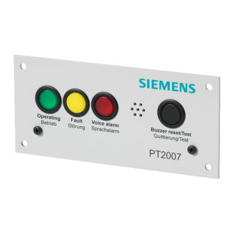
Page 92: System State Indicator Pt2004-A1 And Pt2007-A1
Install internal components System state indicator PT2004-A1 and PT2007-A1 6.12 System state indicator PT2004-A1 and PT2007- The 'System state indicator (19")' PT2004-A1 and 'System state indicator (door)' PT2007-A1 are technically the same. Only the front panel is different. The PT2004-A1 is designed to be mounted in a 19'' cabinet. The PT2007-A1 is designed to be mounted in cabinet doors or control panels. -
Page 93: Connect Inputs And Outputs
Install internal components System state indicator PT2004-A1 and PT2007-A1 6.12.3 Connect inputs and outputs The PT2004-A1 and PT2007-A1 provide one connector ('CN2) with inputs to connect the LEDs and outputs to connect the buttons and the fault relay. Input and output connector - 'CN2' Description Remark Connect to matrix... -
Page 94: Alarm Control Panel Pt2005-A1
Install internal components Alarm control panel PT2005-A1 6.13 Alarm control panel PT2005-A1 The 'Alarm control panel (19")' PT2005-A1 is designed to be mounted in a 19'' cabinet. 6.13.1 Installation The PT2005-A1 provides 7 colored single wires to connect DC 10 V and inputs and output signals to a digital audio matrix. -
Page 95: Pace-Net' Network Switches
6.14 'PACE-Net' network switches Ethernet network switches are used to connect individual Cerberus PACE 'PACE- Net' network components, such as Cerberus PACE digital audio matrices and call stations. All Cerberus PACE Ethernet network switches feature standard copper Ethernet (CAT5) RJ45 sockets for the connection of network components. -
Page 96: Ethernet Switch (2X4/2) Pn2001-A1
Install internal components Ethernet switch (2x4/2) PN2001-A1 6.15 Ethernet switch (2x4/2) PN2001-A1 The 'Ethernet switch (2x4/2)' PN2001-A1 provides: ● 2 independent Ethernet switches with each: – 4 CAT5 copper Ethernet ports (RJ45, 10/100/1000Base-T) and – 1 fiber-optic port (duplex SC) The 'Ethernet switch (2x4/2)' PN2001-A1 comes with 2 separate Ethernet switches to build a fully redundant 'PACE-Net' Ethernet network. -
Page 97: Connect 'Pace-Net' Ethernet
Install internal components Ethernet switch (2x4/2) PN2001-A1 6.15.2 Connect 'PACE-Net' Ethernet The switches are used to build a 'PACE-Net' communication network and to connect 'PACE-Net' digital audio matrices, 'PACE-Net' call stations, Cerberus PACE systems or a PC with the configuration tool 'PACE-Design' installed. The 2 separate, identical Ethernet switches can be used to build a fully redundant network in tree or chain structure or to extend the amount of 'PACE-Net' Ethernet connections. -
Page 98: Planet Igs-10020Mt Switch Pn2005-A1
Install internal components Planet IGS-10020MT Switch PN2005-A1 6.16 Planet IGS-10020MT Switch PN2005-A1 The Ethernet switch 'Planet IGS-10020MT Ethernet Switch' PN2005-A1 provides: ● 8 CAT5 copper Ethernet ports (RJ45, 10/100/1000Base-T) ● 2 fiber-optic ports (SPF ports) ● DC 24 V redundant power supply connection ●... -
Page 99: Connect Dc 24 V Power Supply And Fault Contact
Install internal components Planet IGS-10020MT Switch PN2005-A1 6.16.1 Connect DC 24 V power supply and fault contact The 'Planet IGS-10020MT Ethernet Switch' PN2005-A1 provides one DC 24 V power supply connector with redundant 24 V power connection and a fault relay contact. -
Page 100: Connect 'Pace-Net' Ethernet
Install internal components Planet IGS-10020MT Switch PN2005-A1 6.16.2 Connect 'PACE-Net' Ethernet The switches are used to build a 'PACE-Net' communication network and to connect 'PACE-Net' digital audio matrices, 'PACE-Net' call stations, Cerberus PACE systems or a PC with the configuration tool 'PACE-Design' installed. The Ethernet switch 'Planet IGS-10020MT Ethernet Switch' PN2005-A1 allows to build a redundant Ethernet ring structure. -
Page 101: Planet Igt-805At Converter Pn2007-A1
Install internal components Planet IGT-805AT Converter PN2007-A1 6.17 Planet IGT-805AT Converter PN2007-A1 The media converter 'Planet IGT-805AT Media Converter' PN2007-A1 converts a CAT5 copper based Ethernet section to fiber-optic based Ethernet section. Power 1x fiber optic 1x RJ45 Fig. 74: PN2007-A1 connector overview A6V10430579_en--_b 101 | 173... -
Page 102: Connect Dc 24 V Power Supply And Fault Contact
Install internal components Planet IGT-805AT Converter PN2007-A1 6.17.1 Connect DC 24 V power supply and fault contact The media converter 'Planet IGT-805AT Media Converter' PN2007-A1 provides one DC 24 V power supply connector with redundant 24 V power connection and a fault relay contact. -
Page 103: Connect 'Pace-Net' Ethernet
Install internal components Planet IGT-805AT Converter PN2007-A1 6.17.2 Connect 'PACE-Net' Ethernet The media converter 'Planet IGT-805AT Media Converter' PN2007-A1 converts a CAT5 copper based Ethernet section to fiber-optic based Ethernet section. Fig. 76: PN2007-A1 network connectors The ports 1 is a CAT5 copper Ethernet (RJ45, 10/100/1000Base-T) sockets. The port 2 is a fiber optic slot for inserting a SPF module. -
Page 104: Dc/Dc Converter Pca2011-A1
Install internal components DC/DC converter PCA2011-A1 6.18 DC/DC converter PCA2011-A1 The DC/DC converter 'MeanWell SD-50B-24 DC/DC Converter (50W)' PCA2011- A1 provides an isolated and potential free DC 24 V to connect external components. It ensures a secure DC 24 V in the cabinet in case of a short circuit on the 24 V wiring outside of the cabinet. -
Page 105: Dc/Dc Converter Pca2018-A1
Install internal components DC/DC converter PCA2018-A1 6.19 DC/DC converter PCA2018-A1 The DC/DC converter 'MeanWell SD-100B-24 DC/DC Converter (100W)' PCA2018-A1 provides an isolated and potential free DC 24 V to connect external components. It ensures a secure DC 24 V in the cabinet in case of a short circuit on the 24 V wiring outside of the cabinet. -
Page 106: Rs485 Isolator Pna2009-A1
Install internal components RS485 isolator PNA2009-A1 6.20 RS485 isolator PNA2009-A1 The 'PACE-Bus' (RS485) isolator 'ICPDAS I-7510 (RS485, isolated)' PNA2009-A1 provides an isolated RS485 to connect external components. It ensures a secure 'PACE-Bus' (RS485) in the cabinet in case of a short circuit on the 'PACE-Bus' (RS485) wiring outside of the cabinet. -
Page 107: Earth Fault Monitor Pca2001-A1
Install internal components Earth fault monitor PCA2001-A1 6.21 Earth fault monitor PCA2001-A1 The 'Ground fault monitoring (24V)' PCA2001-A1 detects the earth fault at the isolated DC 24 V wiring to the external components provided by PCA2011-A1 and PCA2018-A1. It ensures that an earth fault on the external DC 24 V wiring outside of the cabinet is detected and reported. -
Page 108: Connect Dc 24 V Power Supply And Earth
Install internal components Call station interface (RS485) PTO2008-A1 6.21.3 Connect DC 24 V power supply and earth The PCA2001-A1 provides one DC 24 V power supply connector ('CN1'). DC 24 V power supply connector - 'CN1' Description Remark DC 24 V Isolated 24 V power supply DC 0 V Isolated 24 V power supply... -
Page 109: Installation
Install internal components Call station interface (RS485) PTO2008-A1 6.22.2 Installation Fig. 81: PTO2008-A1 connector overview The PTO2008-A1 protects the 24 V inside the cabinet with a fuse F1 with a rating of 500 mA. The call stations are connected to 'X5' with single wires or to 'RJ1' with copper Ethernet cable (CAT5). -
Page 110: Connect 'Pace-Bus' (Rs485)
Install internal components Call station interface (RS485) PTO2008-A1 6.22.4 Connect 'PACE-Bus' (RS485) The PTO2008-A1 provides one 'PACE-Bus' (RS485) connector ('X2'). 'PACE-Bus' (RS485) connector - 'X2' Description Remark RS485 data - RS485 data + GND reference voltage Not used Table 67: PTO2008-A1 'PACE-Bus' (RS485) connector - 'X2' 6.22.5 Connect analog audio input The PTO2008-A1 provides one connector ('X3') for an analog audio input connected to the call station microphone output. -
Page 111: Connect To Call Station
Install internal components Call station interface (RS485) PTO2008-A1 6.22.7 Connect to call station The PTO2008-A1 provides two connectors ('X5' and 'RJ1') to connect the call stations. 'RJ1' uses a copper Ethernet cable (CAT5) for the connection. Call station connectors - 'X5' and 'RJ1' Description Remark Audio out -... -
Page 112: Input/Output Extension (Digital 16) Pcio2001-A1
Install internal components Input/Output extension (digital 16) PCIO2001-A1 6.23 Input/Output extension (digital 16) PCIO2001-A1 The 'PACE-Bus' module 'Input/Output extension (digital 16)' PCIO2001-A1 provides: ● 16 logic control outputs with open collector ● 16 logic control inputs ● 8 analog control inputs 6.23.1 Mounting The 'PACE-Bus' module 'Input/Output extension (digital 16)' PCIO2001-A1 is designed to be mounted on a DIN rail in the cabinet. -
Page 113: Configuration With The Id Jumper
Install internal components Input/Output extension (digital 16) PCIO2001-A1 6.23.3 Configuration with the ID jumper The ID jumper must be set to the correct values to identify the components on the 'PACE-Bus' (RS485). The ID must be unique on one 'PACE-Bus' (RS485). The ID jumper 7 and 8 are used to set the RS485 address. -
Page 114: Connect 'Pace-Bus' (Rs485)
Install internal components Input/Output extension (digital 16) PCIO2001-A1 6.23.5 Connect 'PACE-Bus' (RS485) The PCIO2001-A1 provides one 'PACE-Bus' (RS485, RS232) connector ('X5'). 'PACE-Bus' (RS485) connector - 'X5' Description Remark 10 V 10 V reference voltage GND reference voltage RS232 TX - (to connect PCO2001-A1) RS232 RX + (to connect PCO2001-A1) RS485 data + RS485 data -... -
Page 115: Logic Control Inputs
Install internal components Input/Output extension (digital 16) PCIO2001-A1 6.23.6 Logic control inputs The PCIO2001-A1 provides 16 logic control inputs on the two connectors 'X7' and 'X8'. The logic control inputs are used to get information and controls from the connected components. ●... -
Page 116: Analog Control Inputs
Install internal components Input/Output extension (digital 16) PCIO2001-A1 6.23.7 Analog control inputs The PCIO2001-A1 provides one connector ('X9') with 8 analog control inputs. The analog control inputs are used as a local gain control or as a control for audio output volume. -
Page 117: Logic Control Outputs
Install internal components Input/Output extension (digital 16) PCIO2001-A1 6.23.8 Logic control outputs The PCIO2001-A1 provides 16 logic control outputs on the 2 connectors 'X3' and 'X4'. The logic control outputs are used to activate LEDs or communicate a status change of the system. The logic outputs are open collector outputs which switch to GND. -
Page 118: Input/Output Module (Digital, 16) Pcio2002-A1
Install internal components Input/output module (digital, 16) PCIO2002-A1 6.24 Input/output module (digital, 16) PCIO2002-A1 The 'PACE-Bus' module 'Input/output module (digital, 16)' PCIO2002-A1 provides: ● 8 galvanically isolated 2-pole relay outputs with changeover switches ● 16 logic control inputs ● 8 analog control inputs It can be extended with one slave module 'Output extension (relay, 8)' PCO2003- A1 with 8 additional 2-pole relay outputs. -
Page 119: Connect Dc 24 V Power Supply
Install internal components Input/output module (digital, 16) PCIO2002-A1 6.24.4 Connect DC 24 V power supply The PCIO2002-A1 provides one DC 24 V power supply connector ('X1'). DC 24 V power supply connector - 'X1' Description Remark DC 24 V Power supply input DC 0 V Power supply input Table 82: PCIO2002-A1 DC 24 V power supply connector - 'X1'... -
Page 120: Analog Control Inputs
Install internal components Input/output module (digital, 16) PCIO2002-A1 Logic control inputs connector - 'X4' Description Remark GND reference voltage 10 V 10 V reference voltage Table 85: PCIO2002-A1 logic control inputs connector - 'X4' For use of logic control inputs, see Use logic control inputs [➙ 69]. 6.24.7 Analog control inputs The PCIO2002-A1 provides one connector ('X5') with 8 analog control inputs. -
Page 121: Relay Outputs
Install internal components Input/output module (digital, 16) PCIO2002-A1 6.24.8 Relay outputs The PCIO2002-A1 provides 8 relays with 2 poles. Each pole has its own connector. Pole 1 connectors are at 'X1.1' to 'X8.1' and the second pole connectors are at 'X1.2' to 'X8.2'. Relay output connectors pole 1 - 'X1.1' to 'X8.1' Description Remark... -
Page 122: Output Module (Relay, 8) Pco2002-A1
Install internal components Output module (relay, 8) PCO2002-A1 6.25 Output module (relay, 8) PCO2002-A1 The 'PACE-Bus' module 'Output module (relay, 8)' PCO2002-A1 provides 8 galvanically isolated 2-pole relay outputs with changeover switches. It can be extended with one slave module 'Output extension (relay, 8)' PCO2003-A1 with 8 additional 2-pole relay outputs. -
Page 123: Connect Dc 24 V Power Supply
Install internal components Output module (relay, 8) PCO2002-A1 6.25.4 Connect DC 24 V power supply The PCO2002-A1 provides one DC 24 V power supply connector ('X1'). DC 24 V power supply connector - 'X1' Description Remark DC 24 V Power supply input DC 0 V Power supply input Table 90: PCO2002-A1 DC 24 V power supply connector - 'X1'... -
Page 124: Output Extension (Relay, 8) Pco2003-A1
Install internal components Output extension (relay, 8) PCO2003-A1 6.26 Output extension (relay, 8) PCO2003-A1 The slave module 'Output extension (relay, 8)' PCO2003-A1 provides 8 galvanically isolated 2-pole relay outputs with changeover switches. It extends the master modules 'Input/output module (digital, 16)' PCIO2002-A1 or the 'Output module (relay, 8)' PCO2002-A1with one slave module 'Output extension (relay, 8)' PCO2003-A1 with 8 additional 2-pole relay outputs. -
Page 125: Connect External Components
Connect external components Desk call station PT2001-A1 7 Connect external components 7.1 Desk call station PT2001-A1 7.1.1 Mounting The 'PACE-Net' 'Desk call station (19 buttons)' PT2001-A1 is designed to be placed on a desk. It can be extended with up to 4 'Desk call station extension (24 buttons)' PTO2001- A1, each with 24 buttons to a maximum of 115 buttons. -
Page 126: Connect Dc 24 V Power Supply
Fuse (PT2001) PT2002 Fig. 87: PT2001-A1 power supply from a cabinet Cerberus PACE cabinet External 'Desk call station (19 buttons)' PT2001-A1 with accessories DC/DC converter 'MeanWell SD-50B-24 DC/DC Converter (50W)' PCA2011- A1 or 'MeanWell SD-100B-24 DC/DC Converter (100W)' PCA2018-A1 'Ground fault monitoring (24V)' PCA2001-A1... -
Page 127: Connect Pace-Net Ethernet
PCA2018 PTO2009 PT2001 Fig. 88: PT2001-A1 redundant power supply from a cabinet Cerberus PACE cabinet External 'Desk call station (19 buttons)' PT2001-A1 with accessories DC/DC converter 'MeanWell SD-50B-24 DC/DC Converter (50W)' PCA2011- A1 or 'MeanWell SD-100B-24 DC/DC Converter (100W)' PCA2018-A1... -
Page 128: Analog Audio Inputs
Connect external components Desk call station PT2001-A1 7.1.5 Analog audio inputs The PT2001-A1 provides 2 analog audio inputs: ● Analog audio input 1 is used for the attached microphone via the mounted XLR connector. ● Analog audio input 2 can be used for other audio sources. Analog audio input 1 and 2 connector - 'CN1' Description Remark... -
Page 129: Logic Control Outputs
Connect external components Desk call station PT2001-A1 7.1.8 Logic control outputs The PT2001-A1 provides 4 logic outputs. They are open collector transistors switching to GND. The 4 logic control outputs can be used to switch lamps, relays or other components with a current draw of max. 200 mA. The output can be powered with the DC 10 V provided on pin 12 of the connector, or with a voltage of max. -
Page 130: Analog Control Inputs
Connect external components Desk call station PT2001-A1 7.1.9 Analog control inputs The PT2001-A1 provides 6 analog control inputs. These analog control inputs measure the voltage between the GND and the DC 10 V. The values can be used as a local gain control or as control values for the audio output volume. -
Page 131: Pace-Bus' (Rs232) Serial Interface
Connect external components Desk call station PT2001-A1 7.1.10 'PACE-Bus' (RS232) serial interface This 'PACE-Bus' (RS232) interface is used to connect the 'Desk call station extension (24 buttons)' PTO2001-A1. It can be used to connect control panels or for diagnosis. 'PACE-Bus' (RS232) connector - 'CN4' Description Remark Send RS232 data... -
Page 132: Desk Call Station Extension Pto2001-A1
Connect external components Desk call station extension PTO2001-A1 7.2 Desk call station extension PTO2001-A1 7.2.1 Mounting A PT2001-A1 can be extended with up to 4 'Desk call station extension (24 buttons)' PTO2001-A1, each with 24 buttons to a maximum of 115 buttons. The buttons can be labeled with insertable labels. -
Page 133: Connect Rs232
Connect external components Desk call station extension PTO2001-A1 7.2.4 Connect RS232 The PTO2001-A1 has two RS232 connectors. One ('CN4') is used to connect PT2001-A1, and the other ('CN3') is used to communicate with the next PTO2001- RS232 connector 1 - 'CN4' Description Remark Receive RS232 data... -
Page 134: Configuration
Connect external components Desk call station extension PTO2001-A1 7.2.5 Configuration The RS232 communication requires proper ID settings of all PTO2001-A1. Usually the PT2001-A1 are delivered with correct pre-configured ID settings of the connected PTO2001-A1. Fig. 91: PTO2001-A1 keypad numbering 7.2.6 Check the ID settings Follow the steps below to check the ID settings: 1. -
Page 135: Change The Id Settings
Connect external components Desk call station extension PTO2001-A1 7.2.7 Change the ID settings Follow the steps below to change the ID settings: 1. Disconnect the 24 V power supply from the PTO2001-A1. 2. Press and hold the keypads 00 and 11 on the PTO2001-A1. 3. -
Page 136: Desk Call Station Extension (Kaba) Pto2002-A1 And (Nordic) Pto2003-A1
Connect external components Desk call station extension (Kaba) PTO2002-A1 and (Nordic) PTO2003-A1 7.3 Desk call station extension (Kaba) PTO2002-A1 and (Nordic) PTO2003-A1 The optional key switch module 'Desk call station extension (Kaba)' PTO2002-A1 and 'Desk call station extension (Nordic)' PTO2003-A1 enable all or individual call station buttons on PT2001-A1 and its extensions PTO2001-A1 to be released or locked individually. -
Page 137: Fire Brigade Call Station (At) Pt2002-A1
Connect external components Fire brigade call station (AT) PT2002-A1 7.4 Fire brigade call station (AT) PT2002-A1 7.4.1 Mounting The 'PACE-Net' 'Fire brigade call station (AT)' PT2002-A1 is designed to be mounted on a wall with 4 screws. A micro SD card 'ATP AF2GUD-2*** SD 2 GB Card' PCA2002-A1 can be inserted into the micro SD card slot to store and play messages. -
Page 138: Connect Dc 24 V Power Supply
Connect external components Fire brigade call station (AT) PT2002-A1 7.4.3 Connect DC 24 V power supply The DC 24 V power supply connection is used to supply the PT2002-A1 with power. Connect the 24 V to the 'AB-CN1' on the adapter board. DC 24 V power connector - 'AB-CN1' Description Remark... -
Page 139: Fig. 93: Pt2002-A1 Power Supply From A Cabinet
Fuse PT2001 (PT2002) Fig. 93: PT2002-A1 power supply from a cabinet Cerberus PACE cabinet External 'Fire brigade call station (AT)' PT2002-A1 with accessories DC/DC converter 'MeanWell SD-50B-24 DC/DC Converter (50W)' PCA2011- A1 or 'MeanWell SD-100B-24 DC/DC Converter (100W)' PCA2018-A1 'Ground fault monitoring (24V)' PCA2001-A1... -
Page 140: Fig. 94: Pt2002-A1 Redundant Power Supply From A Cabinet
PCA2018 PTO2009 PT2002 Fig. 94: PT2002-A1 redundant power supply from a cabinet Cerberus PACE cabinet External 'Fire brigade call station (AT)' PT2002-A1 with accessories DC/DC converter 'MeanWell SD-50B-24 DC/DC Converter (50W)' PCA2011- A1 or 'MeanWell SD-100B-24 DC/DC Converter (100W)' PCA2018-A1... -
Page 141: Connect Pace-Net Ethernet
Connect external components Fire brigade call station (AT) PT2002-A1 7.4.4 Connect PACE-Net Ethernet The PT2002-A1 provides 2 Ethernet sockets at the PT2001-A1 mother board. Always connect port A (ETH A) with an Ethernet switch. A redundant Ethernet connection can also be established by connecting socket port B (ETH B) with an Ethernet switch. -
Page 142: Logic Control Inputs
Connect external components Fire brigade call station (AT) PT2002-A1 7.4.7 Logic control inputs The PT2002-A1 provides 4 logic control inputs. The 4 logic control inputs can be used to monitor contacts. Logic control inputs connector - 'CN7' Description Remark Logic control input 1 Logic control input 2 Logic control input 3 Logic control input 4... -
Page 143: Logic Control Outputs
Connect external components Fire brigade call station (AT) PT2002-A1 7.4.8 Logic control outputs The PT2002-A1 provides 4 logic control outputs. They are open collector transistors switching to GND. The 4 logic outputs can be used to switch lamps, relays or other components with a current draw of max. -
Page 144: Analog Control Inputs
Connect external components Fire brigade call station (AT) PT2002-A1 7.4.9 Analog control inputs The PT2002-A1 provides 6 analog control inputs. These analog control inputs measure the voltage between the GND and the DC 10 V. The values can be used as a local gain control or as control values for the audio output volume. -
Page 145: Pace-Bus' (Rs232) Serial Interface
Connect external components Fire brigade call station (485, AT) PT2003-A1 7.4.10 'PACE-Bus' (RS232) serial interface This PT2002-A1 'PACE-Bus' (RS232) interface can be used to connect control panels or for diagnosis. 'PACE-Bus' (RS232) connector - 'CN4' Description Remark Send RS232 data Receive RS232 data GND reference voltage Table 115: PT2002-A1 'PACE-Bus' (RS232) connector - 'CN4'... -
Page 146: Pt2003-A1 Connectors
Connect external components Fire brigade call station (485, AT) PT2003-A1 7.5.3 PT2003-A1 connectors To Microphone Mic In Microphone Position Switch Speaker Switch Cabinet connection Speaker Fig. 95: PT2003-A1 connector overview The PT2003-A1 is internally pre-installed. 7.5.4 Microphone input The PT2003-A1 provides one microphone input. This microphone input is used for the handheld microphone. -
Page 147: Speaker Output And Microphone Off-Hook Switch
Interf intern PNA2009 Fig. 96: Wiring of PT2003-A1 with PTO2008-A1 Cerberus PACE cabinet External 'Fire brigade call station (485, AT)' PT2003-A1 DC/DC converter 'MeanWell SD-50B-24 DC/DC Converter (50W)' PCA2011- A1 or 'MeanWell SD-100B-24 DC/DC Converter (100W)' PCA2018-A1 'Ground fault monitoring (24V)' PCA2001-A1... -
Page 148: Configuration With The Id Switch
Connect external components Fire brigade call station (485, AT) PT2003-A1 Call station connectors - 'X1' and 'J1' Description Remark Audio out - Audio out + GND reference voltage RS485 data + RS485 data - DC 24 V DC 24 V Audio in - Audio in + Table 118: PT2003-A1 call station connectors - 'X1' and 'J1'... -
Page 149: Call Station Pt2009-A1
The PT2009-A1 offers RJ45 (J1, J2) connectors at the back of the housing to connect it with the Cerberus PACE cabinet via a copper Ethernet cable (CAT5). This cable is used to wire the 24 V, the 'PACE-Bus' (RS485), the analog audio in and the analog audio out. -
Page 150: Connect To A Cabinet
PT2009 PT2009 Fig. 97: Daisy chain wiring of multiple PT2009-A1 in the standard use case Cerberus PACE cabinet External 'Desk call station (RS485, 8+1)' PT2009-A1 with accessories DC/DC converter 'MeanWell SD-50B-24 DC/DC Converter (50W)' PCA2011- A1 or 'MeanWell SD-100B-24 DC/DC Converter (100W)' PCA2018-A1... -
Page 151: Fig. 98: Star Wiring Of Multiple Pt2009-A1 In The 24 V Redundant Use Case
RS485 Interf Fig. 98: Star wiring of multiple PT2009-A1 in the 24 V redundant use case Cerberus PACE cabinet (3x) external 'Desk call station (RS485, 8+1)' PT2009-A1 with accessories DC/DC converter 'MeanWell SD-50B-24 DC/DC Converter (50W)' PCA2011- A1 or 'MeanWell SD-100B-24 DC/DC Converter (100W)' PCA2018-A1... -
Page 152: Fig. 99: Star Wiring Of Multiple Pt2009-A1 In The Redundant Use Case
Interf PNA2009 Fig. 99: Star wiring of multiple PT2009-A1 in the redundant use case Cerberus PACE cabinet External 'Desk call station (RS485, 8+1)' PT2009-A1 with accessories DC/DC converter 'MeanWell SD-50B-24 DC/DC Converter (50W)' PCA2011- A1 or 'MeanWell SD-100B-24 DC/DC Converter (100W)' PCA2018-A1... -
Page 153: Install Pt2009-A1
Connect external components Call station PT2009-A1 7.6.4 Install PT2009-A1 Unscrew the bottom of the PT2009-A1 for further installation. Microphone Label Audio In Extension Speaker Switch Audio Out 1 Fig. 100: PT2009-A1 connector rear view 7.6.5 Analog audio inputs The PT2009-A1 provides 1 analog audio input. This analog audio input 1 is used for the pre-mounted gooseneck microphone Analog audio input 1 connector - 'CN1' Description... -
Page 154: Analog Audio Outputs
Connect external components Call station PT2009-A1 7.6.6 Analog audio outputs The PT2009-A1 provides 1 analog audio speaker output. This analog audio speaker output 1 is used for the pre-mounted speaker. Analog audio speaker output 1 connector - 'X2' Description Remark Signal + Signal - Table 121: PT2009-A1 analog audio speaker output 1 connector - 'X2'... -
Page 155: Configuration With The Id Switch
Connect external components Call station PT2009-A1 7.6.8 Configuration with the ID switch The ID switch must be set to the correct values to identify the components on the 'PACE-Bus' (RS485). The ID must be unique on one 'PACE-Bus' (RS485). Description Not allowed Not allowed Master component... -
Page 156: Call Station Extension Pto2006-A1
Connect external components Call station extension PTO2006-A1 7.7 Call station extension PTO2006-A1 Mounting The 'Call station extension (RS485, 8)' PTO2006-A1 is a keyboard extension for the 'Desk call station (RS485, 8+1)' PT2009-A1. The buttons can be labeled with insertable labels. The label can be accessed by opening the label lid. - Page 157 Connect external components Call station extension PTO2006-A1 Configuration with the ID switch The ID switch must be set to the correct values to identify the components on the 'PACE-Bus' (RS485). The ID must be unique on one 'PACE-Bus' (RS485). Description Master component First extension component...
-
Page 158: Call Station Interface (Redundant) Pto2009
7.8 Call station interface (redundant) PTO2009 The 'Call station interface (redundant)' PTO2009-A1 provides a redundant 'PACE- Net' and a redundant 24 V connection from the Cerberus PACE system to the call stations PT2001-A1 and PT2002-A1. The PTO2009-A1 has two DC 24 V inputs ('Power In A', 'CN2' and 'Power In B', 'CN3') which are routed to a DC 24 V output ('Power Out' and 'CN5'). -
Page 159: Table 125: Pto2009-A1 Ethernet In Connectors - 'Cn1' And 'Cn3
Connect external components Call station interface (redundant) PTO2009 Ethernet in connectors - 'CN1' and 'CN3' Description Remark: when used in a 2x4 wire cable CAT5 pin CAT5 according to T568B Fire alarm cables color code according to VDE0815 White/orange Grey Orange Yellow White/green... -
Page 160: Rj45 Interface Pna2008-A1
7.9 RJ45 Interface PNA2008-A1 Mounting The 'Camdenboss RJ45 Interface' PNA2008-A1 can be mounted with its DIN rail mount directly in the Cerberus PACE cabinet or in a PT2002-A1 or PT2003-A1 housing. Installation The PNA2008-A1 provides 2 screw terminal connectors (Ethernet single wire 'CN1' and 'CN2') to connect Ethernet cables with single wires (e.g., E30 cables) to... -
Page 161: Table 130: Ethernet Rj45 Connector - 'J1
Connect external components RJ45 Interface PNA2008-A1 Ethernet RJ45 connector - 'J1' Description Remark: when used in a 2x4 wire cable CAT5 according to T568B Fire alarm cables color code according to VDE0815 D1+/TX+ White/orange Grey D1-/TX- Orange Yellow D2+/RX+ White/green Brown Blue White/blue... -
Page 162: Network Repeater Pna2007-A1
Connect external components Network repeater PNA2007-A1 7.10 Network repeater PNA2007-A1 A standard CAT5 copper Ethernet wiring is limited to a length of 100 m. The PNA2007-A1 enables the extension of the CAT5 copper Ethernet wiring by additional 100 m. The PNA2007-A1 comes in a connector box and requires a supply voltage of DC 24 V. -
Page 163: Automatic Volume Control (Avc)
The message should be not too loud when the noise level is low and could be still heard with a high noise level. The Cerberus PACE modular system provides 2 components for the Automatic volume control (AVC) function: ●... -
Page 164: Automatic Volume Control Microphone Pca2007-A1
Connect external components Automatic volume control microphone PCA2007-A1 7.12 Automatic volume control microphone PCA2007-A1 The 'Automated volume control microphone' PCA2007-A1 is used to monitor the noise level in a room. 7.12.1 Mounting and configuration 86 mm Mic Out Base 36 mm Fig. -
Page 165: Automatic Volume Control Module Pca2008-A1
Connect external components Automatic volume control module PCA2008-A1 7.13 Automatic volume control module PCA2008-A1 Up to 4 'Automated volume control microphone' PCA2007-A1 can be connected to an 'Automated volume control module' PCA2008-A1. The PCA2008-A1 mixes these signals and provides one output to adjust the volume. The PCA2008-A1 monitors the wiring to the microphones PCA2007-A1 for short circuit and opens. -
Page 166: Installation
Connect external components Automatic volume control module PCA2008-A1 7.13.2 Installation Power supply DC 24 V The DC 24 V power supply connection 'CN7' is used to supply the PCA2007-A1 with power. DC 24 V power supply connector - 'CN7' Description Remark DC 24 V DC 0 V... -
Page 167: Remote Control Panel Pt2006-A1
Connect external components Remote control panel PT2006-A1 7.14 Remote control panel PT2006-A1 The program channels of the connected digital audio matrix can be controlled with the 'Remote control panel' PT2006-A1. The PT2006-A1 is powered by DC 24 V and communicates via 'PACE-Bus' (RS485) with the digital audio matrix. -
Page 168: Configuration With The Configuration Menu
Connect external components Remote control panel PT2006-A1 7.14.2 Configuration with the configuration menu The PT2006-A1 provides a configuration menu to change the following: ● The brightness of the display ● The RS485 ID The RS485 ID must be set to the correct value to identify the component on the 'PACE-Bus' (RS485). -
Page 169: Eol3 (Active) Pca2004-A1
The PCA2004-A1 can be used in 100 V speaker lines with stub or tree / star configuration. The PCA2004-A1 can be connected to any 100 V Cerberus PACE power amplifier and to the digital audio matrices 'Digital audio matrix (4/4/4)' PC2001-A1, 'Digital audio matrix (0/4/4)' PC2002-A1 and 'Digital audio matrix (4/4/16)' PC2003-A1. -
Page 170: Configuration With The Id Switch
Connect external components EOL3 (active) PCA2004-A1 7.15.1 Configuration with the ID switch The 'EOL3 (active)' PCA2004-A1 provides an ID switch at the outside of its housing to set the EOL3 ID. The EOL3 ID must be set to the correct value to identify the component on the 100 V speaker line. -
Page 171: Installation Of Pca2004-A1
Connect external components EOL3 (active) PCA2004-A1 7.15.2 Installation of PCA2004-A1 The 'EOL3 (active)' PCA2004-A1 is mounted at the end of a 100 V speaker line in stub or tree / star configuration. Up to 16 PCA2004-A1 can be connected to one 100 V power amplifier output with one or more speaker lines. -
Page 172: Loop Isolator (100V) Pca2005-A1
Connect external components Loop isolator (100V) PCA2005-A1 7.16 Loop isolator (100V) PCA2005-A1 The configuration and installation of the 'Loop isolator (100V)' PCA2005-A1 are described in the document A6V11571319 Loop isolator (100V) - technical manual. 172 | 173 A6V10430579_en--_b... - Page 173 Issued by Siemens Switzerland Ltd Smart Infrastructure Global Headquarters Theilerstrasse 1a CH-6300 Zug +41 58 724 2424 www.siemens.com/buildingtechnologies © Siemens Switzerland Ltd, 2018 Technical specifications and availability subject to change without notice. A6V10430579_en--_b...