
Related Manuals for Panasonic CQ-RDP153N


Summary of Contents for Panasonic CQ-RDP153N
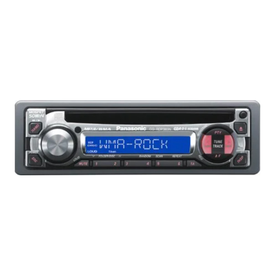
- Page 1 ORDER No. ACED030237C8 AUTOMOTIVE AFTERMARKET CQ-RDP153N / CQ-RDP143N / CQ-RDP133N / CQ-RDP123N / CQ-RDP113N / CQ-RDP103N / CQ-RDP003N Removable Front Panel CD Player / Receiver with CD Changer Control SPECIFICATIONS Specifications*...
- Page 2 General Power Supply DC 12V (11V - 16V), Test Voltage 14.4V Negative Ground Tone Controls Bass ; ±12dB at 100Hz Treble ; ±12dB at 10kHz Current Consumption Less than 2.5A (CD mode, 0.5W× 4ch) 45W×4ch (at 4 Maximum Power Output Speaker Impedance Pre-Amp Output Voltage 2.5V (CD mode)
- Page 3 1. ABOUT LEAD FREE SOLDER (PbF) Distinction of PbF PCB: PCBs (manufactured) using lead free solder will have a PbF stamp on the PCB. Caution : - Pb free solder has a higher melting point than standard solder; Typically the melting point is 50 - 70°F (30 - 40°C) higher. Please use a soldering iron with temperature control and adjust it to 700 ±...
- Page 4 This model has no servo alignment points because microcomputer controls the servo circuit. [OTHER] The following table describes the differences between 7 models. Changer Control Pre-OUT Illumination Color Face Color CQ-RDP153N 4(Front/Rear) Blue/Red Plating Silver CQ-RDP143N 4(Front/Rear) Amber Plating Silver...
- Page 5 7. DIMENSIONS 8. WIRING CONNECTION...
- Page 6 9. BLOCK DIAGRAM...
- Page 7 10. TERMINALS DESCRIPTION...
- Page 8 10.1. Main Block IC601 : C2CBHF000281 Pin No. Port Descriptions I/O(V) FM(V) AM (V) CD (V) (Connecting to ground) (Connecting to ground) (Connecting to ground) AVSS Analog ground AF MUTE AF mute AMP-CNT Power Amp. stand-by AVREF Reference voltage CD-SO CD data CD-SI CD data...
- Page 9 Pin No. Port Descriptions I/O(V) FM(V) AM (V) CD (V) No connection No connection No connection TEL-MUTE Telephone mute PANEL Panel detect CD-CNT CD power control PWR CNT Power control No connection RDS DATA RDS data /RESET Reset input REM-DATA Remocon data input CD_SW1 CD mode SW...
- Page 10 Pin No. Port Descriptions I/O(V) SEG1-8 LCD segment 9-35 SEG9-35 LCD segment 36-39 No connection 40-43 COM1-4 LCD common No connection 45-49 KS2-6 Key data output 50-54 KI1-5 Key data input TEST (Connecting to ground) +5V power supply VDD1 Ground through capacitor VDD2 Ground through capacitor Ground...
- Page 11 Pin No. Port Descriptions Vol.(V) SCKO DAC shift clock LRCKIN DAC LRCK signal LRCK DAC LRCK signal HOLD/WDCK Not used Not used D.GND Digital logic Ground C16M Not used LIMIT (Connecting to VDD) D.VDD (Connecting to VDD) LOCK EFM SYNC detection RFCK Not used MIRR/WFCK...
- Page 12 Pin No. Port Descriptions Vol.(V) Photo detector F input Photo detector E input A.VDD Analog logic power supply REFOUT Reference voltage output Focus error amp input Focus error amp output Tracking error amp input Tracking error amp output Tracking error amp output Tracking comparator input A.GND Analog logic Ground...
- Page 15 IC201 : C1BB00000543...
- Page 16 IC901 : YEAMDA7479D IC271 : C1EA00000026...
- Page 17 IC650 : YEAMC14584BE IC701 : C0EBG0000038 IC703 : C0CAAYG00005...
- Page 18 IC401 : C1BB00000644 11.2. Display Block IC902 : PNA4602M01MC 11.3. CD Servo Block IC301 : C0GBY0000020...
- Page 19 12. REPLACEMENT PARTS LIST Notes : 1. Be sure to make your orders of replacement parts according to this list. 2. Important safety notice: Components, identified by mark have special characteristics important for safety. When replacing any of these components, use only manufacturer's specified parts.
- Page 20 - Order intake period is basically six months after the first shipment. 5. "A", "B", “C”, “D”, “E”, “F” and “G” marks in remarks column are indicated as follows : - A : CQ-RDP153N - B : CQ-RDP143N - C : CQ-RDP133N - D : CQ-RDP123N...
- Page 21 Ref. No. Part No. Part Name & Description Remarks [E6925] Main Block IC's AND TRANSISTORs IC201 C1BB00000543 IC271 C1EA00000026 IC401 C1BB00000644 IC601 C2CBHF000281 IC650 YEAMC14584BE A, B, C IC701 C0EBG0000038 IC702 C0CAAGG00018 IC703 C0CAAYG00005 IC704 C0CAAGG00018 IC705 C0CAADG00035 IC901 YEAMDA7479D PA51 C5BA00000110 Elctronic Tuner...
- Page 22 Ref. No. Part No. Part Name & Description Remarks D706 B0BA8R700011 Diode D707 B0AAMQ000001 Diode D708 YEADRD51JS2T Diode D709 B0BA6R700008 Diode D710 B0EANM000001 Diode B, C, E, F, G D711 YEAD11ES2T Diode CAPACITORs YECUS1H100CC Ceramic, 10PF 50WV F1J1H103A513 Ceramic, 0.01 F 50WV F1J1H103A513 Ceramic, 0.01...
- Page 23 Ref. No. Part No. Part Name & Description Remarks C302 F1J1H681A672 Ceramic, 680PF 50WV C303 YECUS1C334KX Ceramic, 0.33 F 16WV C304 F1J1A2250004 A, B, C Ceramic, 2.2 F 10WV C305 F2A1H1R0A154 Electrolytic, 1 F 50WV C308 F2A1H2R2A154 Electrolytic, 2.2 F 50WV C351 F2A1E4R70028 Electrolytic, 4.7...
- Page 24 Ref. No. Part No. Part Name & Description Remarks C708 YECUS1E104ZF Ceramic, 0.1 F 25WV C709 F2A1H1R0A154 Electrolytic, 1 F 50WV C712 YECUS1E224ZF Ceramic, 0.22 F 25WV C713 YECUS1C224KX Ceramic, 0.22 F 16WV C714 F2A1C470A150 Electrolytic, 47 F 16WV C715 YECUS1C224KX Ceramic, 0.22 F 16WV...
- Page 25 Ref. No. Part No. Part Name & Description Remarks J219 ERJ8GEY0R00V Chip, 0 1/8W J220 ERJ8GX0R00V Chip, 0 1/8W J221 ERJ8GX0R00V Chip, 0 1/8W J223 ERJ8GEY0R00V Chip, 0 1/8W J224 ERJ8GEY0R00V Chip, 0 1/8W J225 ERJ8GEY0R00V Chip, 0 1/8W J226 ERJ8GEY0R00V Chip, 0 1/8W...
- Page 26 Ref. No. Part No. Part Name & Description Remarks ERJ6GEYJ5R6 Chip, 5.6 1/10W ERJ8GEYJ101V Chip, 100 1/8W ERJ6GEYJ471 Chip, 470 1/10W ERJ6GEYJ393 Chip, 39k 1/10W ERJ6GEYJ334 Chip, 330k 1/10W ERJ6GEYJ222 Chip, 2.2k 1/10W ERJ6GEYJ102 Chip, 1k 1/10W R200 ERJ6GEYJ363V Chip, 36k 1/10W R201 ERJ6GEYJ562...
- Page 27 Ref. No. Part No. Part Name & Description Remarks R622 ERJ6GEYJ102 Chip, 1k 1/10W R623 ERJ6GEYJ102 Chip, 1k 1/10W R624 ERJ6GEYJ102 Chip, 1k 1/10W R625 ERJ6GEYJ102 Chip, 1k 1/10W R626 ERJ6GEYJ102 Chip, 1k 1/10W R627 ERJ6GEYJ102 Chip, 1k 1/10W R628 ERJ6GEYJ102 Chip, 1k 1/10W...
- Page 28 Ref. No. Part No. Part Name & Description Remarks R706 ERJ6GEYJ473 Chip, 47k 1/10W R707 ERDS1FJ681 Carbon, 680 1/2W R708 ERDS1FJ681 Carbon, 680 1/2W R709 ERJ6GEYJ133 Chip, 13k 1/10W R710 ERJ6GEYJ113 Chip, 11k 1/10W R712 ERJ6GEYJ223 Chip, 22k 1/10W R713 ERJ6GEYJ154 Chip, 150k 1/10W...
- Page 29 Ref. No. Part No. Part Name & Description Remarks IC's AND TRANSISTORs IC901 YEAMLC75854T IC902 PNA4602M01MC Q901 B1GDCFJJ0002 Transistor DIODEs D901 MA8056LMHTX Diode D902 MA8056LMHTX Diode D903 MA8056LMHTX Diode D904 MA8056LMHTX Diode D905 MA8056LMHTX Diode D909 B3AEB0000025 A, D D909 B3ACB0000100 B, E, G D909...
- Page 30 Ref. No. Part No. Part Name & Description Remarks D925 B3ADB0000043 B, E, G D925 B3ABB0000160 C, F D926 B3AAB0000143 A, D D926 B3ADB0000043 B, E, G D926 B3ABB0000161 C, F D927 B3AAB0000143 A, D D927 B3ADB0000043 B, E, G D927 B3ABB0000161 C, F...
- Page 31 Ref. No. Part No. Part Name & Description Remarks R927 ERJ6GEYJ151 B, C, E, F, G Chip, 150 1/10W R928 ERJ6GEYJ621V A, D Chip, 620 1/10W R928 ERJ6GEYJ560 B, E, G Chip, 56 1/10W R928 ERJ6GEYJ680 C, F Chip, 68 1/10W R929 ERJ6GEYJ621V...
- Page 32 Ref. No. Part No. Part Name & Description Remarks C106 YECUS1E104ZF Ceramic, 0.1 F 25WV C107 ECEV1AA101SP Electrolytic, 100 F 10WV C108 YECUZ1E104ZF Ceramic, 0.1 F 25WV C109 F1J1H102A672 Ceramic, 0.001 F 50WV C120 ECEV1CA100SR Electrolytic, 10 F 16WV C121 ECEV1CA100SR Electrolytic, 10 F 16WV...
- Page 33 J121 ERJ8GEY0R00V Chip, 0 1/8W Ref. No. Part No. Part Name & Description Remarks J122 ERJ8GEY0R00V Chip, 0 1/8W J123 ERJ8GEY0R00V Chip, 0 1/8W J124 ERJ8GEY0R00V Chip, 0 1/8W J125 ERJ8GEY0R00V Chip, 0 1/8W J126 ERJ8GEY0R00V Chip, 0 1/8W J127 ERJ8GEY0R00V Chip, 0 1/8W...
- Page 34 Ref. No. Part No. Part Name & Description Remarks CN402 YEAES03BZRSM Connector, 3P CERAMIC FILTER XL101 H2D169500017 Ceramic Filter COIL L401 YELT03N101JT Coil Accessories PRINTINGs YEFM284003 Operating Instructions (English) YEFM284004 Operating Instructions (German) YEFM284005 Operating Instructions (French) YEFM284006 Operating Instructions (Italian) YEFM284007 Operating Instructions (Spanish) YEFM284008...
- Page 35 Ref. No. Part No. Part Name & Description Remarks YEFX007380 Cord Clamper A, B, C YEFR04187 Lead Cap A, B, C YEFA031817A Upper Cover YEFF011092A Heat Sink YEFX0216060 Bracket, 4P RCA A, B, C YEFX0216059 Bracket, 2P RCA D, E, F, G YEFA05851 Bottom Cover YEFV012227...
- Page 36 Ref. No. Part No. Part Name & Description Remarks YEP0PT6925U9 PCB w/Component, Main PCB RTL, E YEP0PT6925T9 PCB w/Component, Main PCB RTL, F YEP0PT6925S9 PCB w/Component, Main PCB RTL, G YEFX0216133 Bracket, R YEFC027809 Escutcheon Ass'y, Unit YEP0FX5008 Removable Face Plate Unit RTL, A YEP0FX5007 Removable Face Plate Unit...
- Page 37 14. CD PLAYER MECHANICAL PARTS LIST...
- Page 38 Ref. No. Part No. Part Name & Description Remarks YERFA01001 Frame M YERFA01002 Top cover M YERFS04003 Damper F YERFS04004 Damper R YERFA01005 Chassis Rivet S Ass'y (M) YERFX046001 Change Plate Rivet Ass'y (M) YERFX007001 Clamper Ass'y YERAK0001 Spindle Motor (M) Ass'y YERFX046002 Clamper Arm M YERFX005001...
- Page 39 Ref. No. Part No. Part Name & Description Remarks YERFX03010 Loading Gear 5 YERFX03011 Loading Gear 6 YERFX03012 Loading Gear 7 YERFW04004 Roller Guide YERFX005007 Roller Guide Spring YERFX046015 Disc Stopper Arm YERFX005008 Disc Stop Arm Spring YERFX046016 LD Gear Bracket YESFX046133 L Slide Plate YERFX005009...
- Page 40 16. WIRING DIAGRAM 16.1. Main Block (Top View) 16.2. Main Block (Bottom View) 16.3. Display Block 16.4. CD Servo Block...
- Page 41 17. SCHEMATIC DIAGRAM -1 17.1. Display Block 18. SCHEMATIC DIAGRAM -2 18.1. Main Block 18.2. CD Servo Block 19. SCHEMATIC DIAGRAM for Printing with A4 Size 19.1. Main Block (Left Side) 19.2. Main Block (Right Side) 19.3. CD Servo Block (Left Side) 19.4.
- Page 43 [E-9242] [Top View] CQ-RDP153/143/133/123/113/103/003N DECK P.C.B...
- Page 44 [E-9243] [Top View] [E-9243] [Bottom View] CQ-RDP153/143/133/123/113/103/003N DISPLAY P.C.B...
- Page 45 1 80 [E-6925a] [Bottom View] [E-6925b] [Bottom View] CQ-RDP153/143/133/123/113/103/003N MAIN P.C.B...
- Page 46 3 2 1 3 2 1 [E-6925a] [Top View] [E-6925b] [Top View] CQ-RDP153/143/133/123/113/103/003N MAIN P.C.B.
- Page 47 CQ-RDP153N / CQ-RDP143N / CQ-RDP133N / CQ-RDP123N / CQ-RDP113N / CQ-RDP103N / CQ-RDP003N 18.2. CD Servo Block...
- Page 48 Printed in Japan (K) 2003.2 (Recycled Paper)
- Page 49 18 SCHEMATIC DIAGRAM -2 18.1. Main Block...
- Page 50 CQ-RDP153N / CQ-RDP143N / CQ-RDP133N / CQ-RDP123N / CQ-RDP113N / CQ-RDP103N / CQ-RDP003N...
- Page 51 Printed in Japan (K) 2003.2 (Recycled Paper)