
Related Manuals for Fujitsu PRIMERGY GX2570 M6


Summary of Contents for Fujitsu PRIMERGY GX2570 M6
- Page 1 Upgrade and Maintenance Manual - English FUJITSU Server PRIMERGY GX2570 M6 Upgrade and Maintenance Manual 04/2021...
- Page 2 All hardware and software names used are trademarks of their respective manufacturers. The contents of this manual may be revised without prior notice. – Fujitsu assumes no liability for damages to third party copyrights or other rights arising from – the use of any information in this manual.
- Page 3 Before reading this manual For your safety This manual contains important information for safely and correctly using this product. Carefully read the manual before using this product. Pay particular attention to the accompanying manual "Safety Notes and Regulations" and ensure that these safety notes are understood before using the product.
- Page 4 Please consult the sales staff of Fujitsu if intending to use this product for high safety use. Measures against momentary voltage drop This product may be affected by a momentary voltage drop in the power supply caused by lightning.
- Page 5 HDD, see the following internet address: https://jp.fujitsu.com/platform/server/primergy/harddisk/ Only for Japan: Shielded LAN cables should be used in this product. UK Importer information Fujitsu Services Limited 22 Baker Street, London, W1U 3BW, United Kingdom GX2570 M6 Upgrade and Maintenance Manual...
- Page 6 Version history Issue Issue date Description number V 1.0 04/2021 Initial release Upgrade and Maintenance Manual GX2570 M6...
-
Page 7: Table Of Contents
Content Introduction Concept and target groups of this manual Notational conventions Before you start Basic information 2.1.1 Proceeding 2.1.2 Installing optional components 2.1.3 Replacing a defective component Classification of procedures 2.2.1 Assignment of unit categories 2.2.2 Customer Replaceable Units (CRU) 2.2.3 Upgrade and Repair Units (URU) 2.2.4... - Page 8 Content 3.2.4 Batteries 3.2.5 Working with optical disk drives (ODDs) and media 3.2.6 Laser information 3.2.7 Modules with Electrostatic-Sensitive Devices (ESD modules) 3.2.8 Transporting the server 3.2.9 Installing the server in the rack 3.2.10 Other important information CE conformity FCC Class A Compliance Statement Environmental protection Basic hardware procedures Using diagnostic information...
- Page 9 Content Handling the CPU node 4.8.1 Removing the CPU node 4.8.2 Installing the CPU node Handling the GPU node 4.9.1 Removing the GPU node 4.9.2 Installing the GPU node 4.10 Handling the switch board tray 4.10.1 Removing the switch board tray 4.10.2 Installing the switch board tray 4.11...
- Page 10 Content 5.2.8 Looking for the MAC address of a LAN controller 5.2.9 Switching off the ID identicators Power supply unit (PSU) Safety notes Basic information Redundant power supply 6.3.1 Replacing a hot-plug PSU Hard disk drive (HDD) / solid state disk (SSD) Safety notes Basic information Handling HDDs or SSDs without installation frame...
- Page 11 Content Replacing a fan module (GPU node) Replacing a fan board (GPU node) Expansion cards and riser modules Safety notes Basic information Handling slot brackets 9.3.1 Installing slot brackets 9.3.2 Removing slot brackets Handling SFP+ transceiver modules 9.4.1 Installing SFP+ transceiver modules 9.4.2 Removing SFP+ transceiver modules Expansion cards in standard PCIe slots...
- Page 12 Content 10.2.2 General memory population conditions 10.3 Installing memory modules 10.4 Removing memory modules 10.5 Replacing memory modules Processor (CPU) 11.1 Safety notes 11.2 Basic information 11.3 Replacing a CPU or heat sink Graphic processor (GPU) 12.1 Safety notes 12.2 Basic information 12.3 Replacing a GPU or heat sink...
- Page 13 Content 14.2 Basic information 14.3 Replacing the midplane board Front panel 15.1 Safety notes 15.2 Basic information 15.3 Replacing the front panel board 15.4 Replacing the front VGA System board and components 16.1 Safety notes 16.2 Basic information 16.3 CMOS battery 16.3.1 Replacing the CMOS battery 16.4...
- Page 14 Content 17.2.2.2 Indicators on the front panel 17.2.2.3 LAN indicators on the front panel 17.2.2.4 Indicators on hot-plug HDD/SSD modules 17.2.3 Server rear 17.2.3.1 Indicators on hot-plug HDD/SSD modules 17.2.3.2 Indicator on hot-plug PSU 17.2.4 Acoustic indicators 17.3 Onboard settings 17.4 Minimum startup configuration Appendix B...
-
Page 15: Introduction
Introduction Concept and target groups of this manual This upgrade and maintenance manual provides instructions for the following procedures: – Upgrading the server configuration by adding optional hardware components. – Upgrading the server configuration by replacing existing hardware components with superior ones. –... - Page 16 Introduction ▶ Describes activities that must be performed in the order shown. [Abc] Indicates keys on the keyboard. Pay particular attention to texts marked with this CAUTION symbol. Failure to observe this warning may endanger your life, destroy the system or lead to the loss of data.
-
Page 17: Before You Start
For Japan: https://www.fujitsu.com/jp/products/computing/servers/primergy/ Please contact your local Fujitsu customer service partner for details on how to order expansion kits or spare parts. GX2570 M6 Upgrade and Maintenance Manual... -
Page 18: Replacing A Defective Component
At the beginning of each procedure, the involved unit category is indicated by one of the symbols introduced in this section. Please ask your local Fujitsu service center for more information. 2.2.2 Customer Replaceable Units (CRU) -
Page 19: Upgrade And Repair Units (Uru)
(Repair Units). For Japan, customer allows only upgrade. For upgrade units as customer replaceable, see: https://www.fujitsu.com/jp/products/computing/servers/primergy/ Upgrade and repair procedures involve shutting down and opening the server. CAUTION The device may be seriously damaged or cause damage if it is opened without authorization or if repairs are attempted by unauthorized and untrained personnel. -
Page 20: Field Replaceable Units (Fru)
CAUTION Maintenance procedures involving Field Replaceable Units must be performed exclusively by Fujitsu service personnel or technicians trained by Fujitsu. Please note that unauthorized interference with the system will void the warranty and exempt the manufacturer from all liability. Components that are handled as Field Replaceable Units –... -
Page 21: Average Task Duration
Before you start Please ask your local Fujitsu service center for more information. Average task duration Hardware: 10 minutes The average task duration including preliminary and concluding steps is indicated at the beginning of each procedure next to the procedure class. -
Page 22: Tools You Need At Hand
▶ Ensure to store all printed manuals enclosed with your server in a save place for future reference. ▶ When preparing the maintenance task, ensure that all required manuals are available, see Table 2. If applicable, download the manual from the following address: https://support.ts.fujitsu.com/ For Japan: https://www.fujitsu.com/jp/products/computing/servers/primergy/manual/ Upgrade and Maintenance Manual GX2570 M6... -
Page 23: List Of Documents
Important safety information, available online, Regulations" manual or as a printed copy "安全上のご注意" for Japan "FUJITSU Server Information how to install, set up and operate PRIMERGY GX2570 M6 your server, available online Operating Manual" "FUJITSU Server Instructions for upgrading the server PRIMERGY GX2570 M6... - Page 24 Before you start Document Description "Returning used devices" Recycling and contact information, available manual online at https://ts.fujitsu.com/recycling, or as a printed copy "Service Desk" leaflet Not applicable in Japan and other countries that "サポート&サービス" for have different regulations for recycling...
-
Page 25: Important Information
Important information Introduction In this chapter you will find essential information regarding safety when working on your server. Depending on your server or the installed options some information is not valid for your server. CAUTION ▶ Before installing and starting up a server, please observe the safety instructions listed in the following section. -
Page 26: Before Starting Up
Important information ▶ Only valid for non hot-plug components Before installing/removing internal components to/from the server, turn off the server, all peripheral devices, and any other connected devices. Also unplug all power cords from the power outlet. Failure to do so can cause electric shock or damage. - Page 27 Important information ▶ If a DC power cord is used, the server must be connected to a proper DC source and earth ground stud/end. ▶ Ensure that the server is connected to a properly grounded power outlet close to the server. ▶...
- Page 28 Important information ▶ Proper operation of the server (in accordance with IEC 60950-1/62368-1 resp. EN 60950-1/62368-1) is only ensured if the server is completely assembled and the rear covers for the installation slots have been fitted (electric shock, cooling, fire protection, interference suppression). ▶...
-
Page 29: Batteries
Important information ▶ Install the screw removed during installation/detaching internal options in former position. To use a screw of the different kind can cause a breakdown of equipment. ▶ The procedure of installation on this notes might change depending on a configuration of option. - Page 30 Important information CAUTION ▶ Only use CDs/DVDs/BDs that are in perfect condition, in order to prevent data loss, equipment damage and injury. ▶ Check each CD/DVD/BD for damage, cracks, breakages etc. before inserting it in the drive. Note that any additional labels applied may change the mechanical properties of a CD/DVD/BD and cause imbalance and vibrations.
-
Page 31: Laser Information
Important information ▶ Do not bend or place heavy objects on CDs/DVDs/BDs. ▶ Do not write with ballpoint pen or pencil on the label (printed) side. ▶ Do not attach stickers or similar to the label side. Doing so may cause rotational eccentricity and abnormal vibrations. - Page 32 Important information Figure 1: ESD label The ESD label can be different. When you handle ESD modules, you must always observe the following points: ▶ Switch off the server and remove the power plugs from the power outlets before installing or removing ESD modules. ▶...
-
Page 33: Transporting The Server
Important information 3.2.8 Transporting the server CAUTION ▶ Only transport the server in its original packaging or in packaging that protects it from impacts and jolts. In Japan and APAC, transporting the server in its original packaging does not apply. ▶... -
Page 34: Installing The Server In The Rack
Important information 3.2.9 Installing the server in the rack CAUTION ▶ For safety reasons, at least 2 people are required to install the server in the rack because of its weight and size. (For Japan, see "安全上のご注意".) ▶ Never lift the server into the rack using the QRLs on the front panel. ▶... -
Page 35: Ce Conformity
▶ Select the subclass, e.g. "Rack server". ▶ Select your server, e.g. "PRIMERGY GX2570 M6". ▶ Select the document, e.g. "CE Cert PRIMERGY GX2570 M6". FCC Class A Compliance Statement If there is an FCC statement on the device, it applies to the products covered in this manual, unless otherwise specified herein. -
Page 36: Environmental Protection
▶ Consult the dealer or an experienced radio/TV technician for help. Fujitsu is not responsible for any radio or television interference caused by unauthorized modifications of this equipment or the substitution or attachment of connecting cables and equipment other than those specified by Fujitsu. The correction of interferences caused by such unauthorized modification, substitution or attachment will be the responsibility of the user. - Page 37 Important information Packaging information This packaging information does not apply in Japan and APAC. Do not throw away the packaging. You may need it later for transporting the server. If possible, the equipment should only be transported in its original packaging. Information on handling consumables Please dispose of printer consumables and batteries in accordance with the applicable national regulations.
- Page 38 More information can be found at: https://ts.fujitsu.com/recycling Details regarding the return and recycling of devices and consumables within Europe can also be found in the "Returning used devices" manual, via your local Fujitsu branch, or at: https://ts.fujitsu.com/recycling Upgrade and Maintenance Manual GX2570 M6...
-
Page 39: Basic Hardware Procedures
Using diagnostic information 4.1.1 Proceeding In Japan remote diagnostics procedures are not used. Please contact your local Fujitsu customer service partner for details on the service concept and on how to order expansion kits or spare parts. 4.1.2 Locating the defective server... -
Page 40: Shutting Down The Server
Basic hardware procedures Shutting down the server CAUTION ▶ For more information, see "Important information" on page This step is only required when upgrading or replacing non-hot-plug components. ▶ Inform the system administrator that the server will be shut down and put offline. -
Page 41: Getting Access To The Component
Basic hardware procedures Getting access to the component 4.4.1 Safety notes CAUTION ▶ Only for non-hot plug components: ● Before removing or attaching covers, turn off the server, all peripheral devices, and any other connected devices. ● Because there is a risk of electric shock or damage, please disconnect all power cords from the outlet. - Page 42 Basic hardware procedures Figure 3: Loosening the screws ▶ Loosen the two knurled screws (see circles). Figure 4: Extending the server out of the rack ▶ Pull the server with the installed rack rails out of the rack as far as possible. CAUTION ▶...
-
Page 43: Removing The Server From The Rack
Basic hardware procedures 4.4.3 Removing the server from the rack In most cases maintenance tasks can be performed while the server is extended from the rack. However, depending on accessibility or security guidelines, it may make sense to completely remove the server from the rack cabinet for maintenance purposes. - Page 44 Basic hardware procedures Additionally, a lifter is required in the following cases: – The server weighs more than 50 kg. – The server weighs more than 21 kg and is to be removed above the height of 25 U. When using a lifter, this removal procedure needs to be carried out by maintenance personnel.
-
Page 45: Reassembling
Basic hardware procedures Reassembling 4.5.1 Safety notes CAUTION ▶ Before attaching the covers, make sure no unnecessary parts or tools are left inside the server. ▶ The top cover must be replaced as soon as possible for purposes of cooling, to comply with EMC regulations (regulations regarding electromagnetic compatibility) and to prevent fires. - Page 46 Basic hardware procedures For configurations above 55 kg: At least four people are needed to lift the server into the rack cabinet. Additionally, a lifter is required in the following cases: – The server weighs more than 50 kg. – The server weighs more than 21 kg and is to be installed above the height of 25 U.
-
Page 47: Sliding The Server Into The Rack
Basic hardware procedures 4.5.3 Sliding the server into the rack Figure 7: Sliding the server into the rack ▶ Push the server as far as it will go into the rack. Figure 8: Fastening the server in the rack ▶ Fasten the server in the rack with the two knurled screws. ▶... -
Page 48: Connecting The Power Cord
Basic hardware procedures Connecting the power cord CAUTION The server automatically adjusts to a mains voltage in the range from 200 V - 240 V. ▶ You may only operate the server if its rated voltage range corresponds to the local mains voltage. Figure 9: Connecting the power cord ▶... -
Page 49: Switching On The Server
Basic hardware procedures Switching on the server CAUTION ▶ Before switching on the server, make sure the top cover is closed. In order to comply with applicable EMC regulations (regulations on electromagnetic compatibility) and satisfy cooling requirements, the server must not run while the top cover is removed. ▶... -
Page 50: Installing The Cpu Node
Basic hardware procedures Figure 11: Pulling out the CPU node ▶ Hold the CPU node by the handles (see circles). ▶ Pull out the CPU node by pressing the locking levers (see close-ups). 4.8.2 Installing the CPU node Figure 12: Installing the CPU node Upgrade and Maintenance Manual GX2570 M6... -
Page 51: Handling The Gpu Node
Basic hardware procedures ▶ Hold the CPU node by the handles (see circles). ▶ Slide in the CPU node until the locking levers engage. Figure 13: Fastening the screw ▶ Fasten the screw (see circle). Handling the GPU node 4.9.1 Removing the GPU node Figure 14: Loosening the screws ▶... - Page 52 Basic hardware procedures Figure 15: Removing the GPU node ▶ Hold the GPU node by the handles (see circles). ▶ Pull out the GPU node by pressing the locking levers (see close-ups). Upgrade and Maintenance Manual GX2570 M6...
-
Page 53: Installing The Gpu Node
Basic hardware procedures 4.9.2 Installing the GPU node Figure 16: Installing the GPU node ▶ Hold the GPU node by the handles (see circles). ▶ Slide in the GPU node until the locking levers engage. Figure 17: Fastening the screws GX2570 M6 Upgrade and Maintenance Manual... -
Page 54: Handling The Switch Board Tray
Basic hardware procedures ▶ Fasten the two screws (see circles). 4.10 Handling the switch board tray 4.10.1 Removing the switch board tray Figure 18: Loosening the screws ▶ Loosen the two screws (see circles). Upgrade and Maintenance Manual GX2570 M6... -
Page 55: Installing The Switch Board Tray
Basic hardware procedures Figure 19: Removing the switch board tray ▶ Hold the switch board tray by the handles (see circles). ▶ Pull out the switch board tray in the direction of the arrow. 4.10.2 Installing the switch board tray Figure 20: Installing the switch board tray GX2570 M6 Upgrade and Maintenance Manual... - Page 56 Basic hardware procedures ▶ Hold the switch board tray by the handles. ▶ Install the switch board tray in the direction of the arrow. Figure 21: Fastening the screws ▶ Fasten the two screws (see circles). Upgrade and Maintenance Manual GX2570 M6...
-
Page 57: Handling The Riser Module
Basic hardware procedures 4.11 Handling the riser module 4.11.1 Removing the riser module Figure 22: Opening the locks ▶ Open the two locks. ▶ Pull out the two locks. GX2570 M6 Upgrade and Maintenance Manual... - Page 58 Basic hardware procedures Figure 23: Disconnecting the power cable ▶ Disconnect the power cable (see circles). Upgrade and Maintenance Manual GX2570 M6...
- Page 59 Basic hardware procedures Figure 24: Removing the riser module ▶ Grip the riser module by the holes (see circles). ▶ Remove the riser module. GX2570 M6 Upgrade and Maintenance Manual...
-
Page 60: Installing The Riser Module
Basic hardware procedures 4.11.2 Installing the riser module Figure 25: Installing the riser module ▶ Grip the riser module by the holes (see circles). ▶ Install the riser module. Upgrade and Maintenance Manual GX2570 M6... - Page 61 Basic hardware procedures Figure 26: Connecting the power cable ▶ Connect the power cable (see circles). Figure 27: Closing the locks ▶ Push in the two locks. ▶ Close the two locks. GX2570 M6 Upgrade and Maintenance Manual...
-
Page 62: Handling The Air Duct
Basic hardware procedures 4.12 Handling the air duct 4.12.1 Removing the air duct Figure 28: Removing the air duct ▶ Remove the three screws (1). ▶ Remove the air duct upwards (2). Upgrade and Maintenance Manual GX2570 M6... -
Page 63: Installing The Air Duct
Basic hardware procedures 4.12.2 Installing the air duct Figure 29: Installing the air duct ▶ Install the air duct (1). ▶ Fasten the three screws (2). 4.13 Handling the cross bar 4.13.1 Removing the cross bar Figure 30: Removing the screws GX2570 M6 Upgrade and Maintenance Manual... - Page 64 Basic hardware procedures ▶ Remove one screw at each side (1). ▶ Remove the screw (2). Figure 31: Note on removing the cross bar It is not necessary to remove the screws inside the orange circle. Figure 32: Removing the cross bar ▶...
-
Page 65: Installing The Cross Bar
Basic hardware procedures 4.13.2 Installing the cross bar Figure 33: Installing the cross bar ▶ Install the cross bar. ▶ Ensure that the recesses on the left and right sides of the cross bar fit into the guiding pins of the chassis (see close-ups). Figure 34: Fastening the screws ▶... - Page 66 Basic hardware procedures Upgrade and Maintenance Manual GX2570 M6...
-
Page 67: Basic Software Procedures
Basic software procedures Starting the maintenance task 5.1.1 Disabling the boot watchdog The boot watchdog determines whether the OS boots within a preset time frame. If the watchdog timer expires, the system will automatically reboot. If the system is to be started from removable boot media for firmware upgrade purposes, the boot watchdog needs to be disabled before starting maintenance task. -
Page 68: Backing Up The Setting Information Of Bios Or Bmc
For more information on suitable backup software solutions and related documentation, see the Fujitsu web pages. 5.1.3 Backing up the setting information of BIOS or... - Page 69 After updating or recovering the BIOS and BMC, ensure that the boot watchdog is enabled, see "Enabling the boot watchdog" on page Fujitsu does not assume responsibility for any damage done to the server or for the loss of any data resulting from BIOS updates. BIOS flash procedure ▶...
- Page 70 Basic software procedures ▶ Choose one of the following options from the update tool menu to start the BMC update process: Normal: Choose this option to update an existing system board. Initial: Choose this option if the system board has been replaced prior to the BMC update procedure.
-
Page 71: Enabling Option Rom Scan
Basic software procedures ▶ Choose the Recovery_L option from the update tool menu to start the BMC update process. CAUTION If the process is interrupted, the BMC may be permanently corrupted. ▶ Do not interrupt the BMC upgrade process after it has started. If the BMC does not work after flashing, disconnect the system from the mains and reconnect it again. -
Page 72: Enabling The Boot Watchdog
Basic software procedures ▶ Save your changes and exit the firmware. The option ROM of the expansion card can now be disabled in the BIOS. Exception: If the expansion card controls a permanent boot device, the Option ROM of the expansion card has to remain enabled. 5.2.3 Enabling the boot watchdog If the boot watchdog has been disabled for firmware upgrade purposes (see... -
Page 73: Viewing And Clearing The System Event Log (Sel)
Basic software procedures If a Linux OS is used and the hardware clock has been configured as UTC (Universal Time, Coordinated) in the OS, the BMC local time may not be mapped correctly. ▶ After replacing the system board, ask the system administrator whether the RTC or UTC time standard is to be used as system time. -
Page 74: Updating The Nic Configuration File In A Linux Environment
Basic software procedures ▶ Under Event Log the SEL is displayed. All events concerning the system are displayed in a table in the Event Log Content group. ▶ You can sort the table based on a column using the arrows in the header field. -
Page 75: Performing A Raid Array Rebuild
Basic software procedures To update the MAC address, proceed as follows: ▶ After replacing a network controller or the system board, switch on and boot the server, see "Switching on the server" on page The hardware configuration tool for Red Hat Linux, will launch at boot and detect the new and/or changed hardware on your system. -
Page 76: Looking For The Mac Address Of A Lan Controller
Basic software procedures Figure 35: Progress bar (RAID array rebuild) CAUTION The system is now operational, however, data redundancy will not be available until the RAID array rebuild is complete. Depending on the HDD capacity the overall process can take up to several hours, in some cases even days. -
Page 77: Switching Off The Id Identicators
Basic software procedures ▶ Inform the customer about the new or changed MAC address. Checking the label ▶ If available, check the label on the controller. Beside the part number, you may find the MAC address. Using an UEFI BIOS ▶... - Page 78 Basic software procedures Upgrade and Maintenance Manual GX2570 M6...
-
Page 79: Power Supply Unit (Psu)
Power supply unit (PSU) Safety notes CAUTION ▶ Do not disassemble the PSU. Doing so may cause electric shock. ▶ Areas around the PSU may remain extremely hot after shutdown. After shutting down the server, wait for hot components to cool down before removing the PSU. -
Page 80: Redundant Power Supply
Power supply unit (PSU) PSU configurations PSU 3 Figure 36: PSU bays Input Output 200 - 240 V 2200 W Assembly rules – Only use the allowed PSU configuration with four hot-plug PSUs (2200 W). – For a redundant power supply configuration you need always four PSUs with the same power class. - Page 81 Power supply unit (PSU) CAUTION ▶ When replacing a PSU in a non-redundant PSU configuration, the server must be switched off first. ▶ Replace the PSU after specifying the one that breaks down at work by revitalization. Preliminary steps ▶ "Locating the defective server"...
- Page 82 Power supply unit (PSU) Removing the defective hot-plug PSU Figure 37: Removing a hot-plug PSU ▶ Pull up the locking lever (1). ▶ Remove the PSU (2). CAUTION Excessive temperatures could damage system components. ▶ Never leave the bay for the hot-plug PSU empty for more than two minutes during operation.
- Page 83 Power supply unit (PSU) Installing the new hot-plug PSU Figure 38: Installing a hot-plug PSU ▶ Ensure that the locking lever is pulled up. ▶ Push the PSU into its bay as far as it will go (1). ▶ Pull down the locking lever to insert the PSU completely (2). Ensure that the PSU engages correctly in the bay and is locked in position.
- Page 84 Power supply unit (PSU) Concluding steps ▶ Connect the power cord to the new PSU, see "Connecting the power cord" on page ▶ Only when replacing a PSU in a non-redundant configuration: "Switching on the server" on page Upgrade and Maintenance Manual GX2570 M6...
-
Page 85: Hard Disk Drive (Hdd) / Solid State Disk (Ssd)
Hard disk drive (HDD) / solid state disk (SSD) Safety notes CAUTION ▶ Before removing several HDD/SSD modules, make sure that all HDD/SSD modules can be reinstalled into their original bay. Otherwise, data may be lost. ▶ Do not touch the circuitry on boards or soldered parts. Hold circuit boards by their metallic areas or edges. -
Page 86: Basic Information
Hard disk drive (HDD) / solid state disk (SSD) Basic information The HDD or SSD and the installation frame together make up the HDD module or SSD module. The server is shipped with a 2.5-inch HDD/SSD subsystem: – Up to six 2.5-inch SAS/SATA HDD/SSD modules can be installed at the server front. - Page 87 Hard disk drive (HDD) / solid state disk (SSD) Installing a 2.5-inch HDD/SSD in a 2.5-inch installation frame Figure 39: Inserting the HDD/SSD in the installation frame ▶ Insert the HDD/SSD in the installation frame. Ensure that the four holes at the bottom side of the HDD/SSD fit in the guiding pins of the installation frame.
-
Page 88: Inch Hdd/Ssd Configurations
Hard disk drive (HDD) / solid state disk (SSD) Removing a 2.5-inch HDD/SSD from a 2.5-inch installation frame Figure 40: Removing the HDD/SSD from the installation frame ▶ Remove the HDD/SSD from the tray by pressing the figure with your finger (see circle). - Page 89 Hard disk drive (HDD) / solid state disk (SSD) Figure 41: Configuration with six 2.5-inch HDD/SSDs - front view Figure 42: Configuration with four 2.5-inch HDD/SSDs - rear view Position Component HDD 0 HDD 1 HDD 2 HDD 3 HDD 4 HDD 5 HDD 6 HDD 7...
-
Page 90: Installing 2.5-Inch Hdd/Ssd Modules
Hard disk drive (HDD) / solid state disk (SSD) 7.4.2 Installing 2.5-inch HDD/SSD modules Customer Replaceable Hardware: 5 minutes Unit (CRU) Tools: tool-less Preliminary steps ▶ Locate the correct drive bay, see "Overview of configurations" on page Removing a 2.5-inch HDD/SSD dummy module The dummy module is the installation frame without an installed HDD/ SSD. - Page 91 Hard disk drive (HDD) / solid state disk (SSD) Installing a 2.5-inch HDD/SSD module ▶ Install the HDD/SSD in the installation frame, see "Installing a 2.5-inch HDD/ SSD in a 2.5-inch installation frame" on page Figure 44: Installing the 2.5-inch HDD/SSD module ▶...
-
Page 92: Removing 2.5-Inch Hdd/Ssd Modules
Hard disk drive (HDD) / solid state disk (SSD) 7.4.3 Removing 2.5-inch HDD/SSD modules Customer Replaceable Hardware: 5 minutes Unit (CRU) Tools: tool-less Preliminary steps ▶ If the HDD/SSD module to be removed is combined into a RAID array, please proceed as follows: RAID level Procedure RAID 0... - Page 93 Hard disk drive (HDD) / solid state disk (SSD) Removing a 2.5-inch HDD/SSD module Figure 45: Removing a 2.5-inch HDD/SSD module ▶ Pinch the green release button and open the locking lever (1). ▶ Pull the HDD/SSD module out a few centimeters (2). ▶...
-
Page 94: Replacing A 2.5-Inch Hdd/Ssd Module
Hard disk drive (HDD) / solid state disk (SSD) The dummy module is the installation frame without an installed HDD/ SSD. Figure 46: Installing the 2.5-inch HDD/SSD dummy module ▶ Push the dummy module into the empty bay as far as it will go (1). ▶... - Page 95 Hard disk drive (HDD) / solid state disk (SSD) CAUTION ▶ Only remove an HDD/SSD module during operation if the drive is not currently being accessed. Observe the indicators on the corresponding HDD/SSD module, see "Indicators on hot-plug HDD/ SSD modules" on page 266.
-
Page 96: Replacing The 6X 2.5-Inch Hdd Backplane (Front)
Hard disk drive (HDD) / solid state disk (SSD) Removing the defective 2.5-inch HDD/SSD module ▶ Remove the HDD/SSD module, see "Removing 2.5-inch HDD/SSD modules" on page ▶ If applicable, remove the HDD/SSD from the installation frame, see "Handling HDDs or SSDs without installation frame" on page Installing the new 2.5-inch HDD module ▶... - Page 97 Hard disk drive (HDD) / solid state disk (SSD) ▶ Remove all HDD/SSD modules, see "Removing a 2.5-inch HDD/SSD module" on page CAUTION The HDD modules need not to be removed. ▶ If you want to remove them nevertheless, check if all HDD modules are uniquely identified so that you can reinsert them into their original bays.
- Page 98 Hard disk drive (HDD) / solid state disk (SSD) Installing the new HDD backplane Figure 49: Installing the HDD backplane ▶ Insert the HDD backplane. ▶ Fasten the four screws (see circles). Figure 50: Connecting cables ▶ Connect all cables to the HDD backplane. Concluding steps ▶...
-
Page 99: Replacing The 4X 2.5-Inch Hdd Backplane (Rear)
Hard disk drive (HDD) / solid state disk (SSD) 7.4.6 Replacing the 4x 2.5-inch HDD backplane (rear) Field Replaceable Unit Hardware: 10 minutes (FRU) Tools: Phillips PH2 / (+) No. 2 screw driver Preliminary steps ▶ "Locating the defective server" on page ▶... - Page 100 Hard disk drive (HDD) / solid state disk (SSD) Removing the defective HDD backplane (rear) Figure 51: Disconnecting all cables ▶ Disconnect all cables from the HDD backplane as shown. Figure 52: Removing the HDD backplane (rear) ▶ Loosen the two knurled screws (1). ▶...
- Page 101 Hard disk drive (HDD) / solid state disk (SSD) Installing the new HDD backplane (rear) Figure 53: Installing the HDD backplane (rear) ▶ Position the HDD backplane on the position pin (1) and push the HDD backplane down (2). ▶ Fasten the two knurled screws (3). Figure 54: Connecting cables ▶...
- Page 102 Hard disk drive (HDD) / solid state disk (SSD) Concluding steps ▶ Insert all HDD/SSD modules, see "Installing a 2.5-inch HDD/SSD module" on page Make sure that you reinstall the HDD/SSD module in the bay it was located before the HDD backplane replacement. ▶...
-
Page 103: Fans
Fans Safety notes CAUTION ▶ Do not damage or modify internal cables or devices. Doing so may cause a device failure, fire, or electric shock. ▶ Devices and components inside the server remain hot after shutdown. After shutting down the server, wait for hot components to cool down before installing or removing internal options. - Page 104 Fans Figure 55: Numbering of the fan modules (CPU node) Fan 1 Fan 5 Fan 2 Fan 6 Fan 3 Fan 7 Fan 4 Fan 8 As an option, an LC kit can be installed. In this case fan 3 is occupied by the tubes of the LC kit.
-
Page 105: Replacing A Fan Module (Cpu Node)
Fans Figure 56: Numbering of the fan modules (GPU node) - air cooling Fan 1 Fan 3 Fan 2 Fan 4 Configuration with liquid cooling: The server is equipped with two fan modules on the GPU node. Figure 57: Numbering of the fan modules (GPU node) - liquid cooling Fan 1 Fan 4 Replacing a fan module (CPU node) - Page 106 Fans Tools: Phillips PH2 / (+) No. 2 screw driver (for CPU node) Preliminary steps ▶ "Locating the defective server" on page ▶ "Locating the defective component" on page ▶ "Shutting down the server" on page ▶ "Getting access to the component" on page ▶...
- Page 107 Fans Installing the new fan module (CPU node) Figure 59: Aligning the fan module ▶ Algin the fan module with the guide pins on the CPU node (see circles). ▶ Align the fan module to the fan connector (see close-up). GX2570 M6 Upgrade and Maintenance Manual...
-
Page 108: Replacing A Fan Module (Gpu Node)
Fans Figure 60: Installing the fan module ▶ Take the fan module by the two handles (1). ▶ Install the fan module (2). Concluding steps ▶ "Installing the cross bar" on page ▶ "Installing the CPU node" on page ▶ "Reassembling"... - Page 109 Fans Perform the replacement of the fan module within ten seconds. Preliminary steps No steps needed. Removing a defective fan module (GPU node) Figure 61: Removing a fan module ▶ Press the locking latches inside (1). ▶ Remove the fan module (2). GX2570 M6 Upgrade and Maintenance Manual...
-
Page 110: Replacing A Fan Board (Gpu Node)
Fans Installing a new fan module (GPU node) Figure 62: Installing a fan module ▶ Hold the fan module by the locking latches (1). ▶ Install the fan module until it engages (2). Concluding steps No steps needed. Replacing a fan board (GPU node) Field Replaceable Unit Hardware: 10 minutes (FRU) - Page 111 Fans Preliminary steps ▶ "Locating the defective server" on page ▶ "Locating the defective component" on page ▶ "Shutting down the server" on page ▶ "Getting access to the component" on page ▶ Remove all fan modules (GPU node), see "Removing a defective fan module (GPU node)"...
- Page 112 Fans Figure 64: Loosening the screws ▶ Loosen the five screws (see circles). ▶ Remove the fan board. Upgrade and Maintenance Manual GX2570 M6...
- Page 113 Fans Installing the new fan board (GPU node) Figure 65: Fastening the screws ▶ Install the fan board. ▶ Fasten the five screws (see circles). GX2570 M6 Upgrade and Maintenance Manual...
- Page 114 Fans Figure 66: Connecting cables ▶ Connect all power cables to the fan board. Concluding steps ▶ "Installing the GPU node" on page ▶ Install all fan modules (GPU node), see "Installing a new fan module (GPU node)" on page 110.
-
Page 115: Expansion Cards And Riser Modules
Expansion cards and riser modules Safety notes CAUTION ▶ Do not damage or modify internal cables or devices. Doing so may cause a device failure, fire, or electric shock. ▶ Devices and components inside the server remain hot after shutdown. After shutting down the server, wait for hot components to cool down before installing or removing internal options. -
Page 116: Basic Information
Expansion cards and riser modules Basic information Expansion cards Figure 67: OCP slot and PCIe slots - rear view Figure 68: PCIe slots (switch board) Upgrade and Maintenance Manual GX2570 M6... - Page 117 PCIe 4.0 x16 low profile slot, half length For system relevant information, see the hardware configurator of your server available online at the following address: https://www.fujitsu.com/emeia/products/computing/servers For Japan: https://www.fujitsu.com/jp/products/computing/servers/primergy/ Riser module (CPU node) Figure 69: PCIe slots of the riser module...
-
Page 118: Handling Slot Brackets
Expansion cards and riser modules Pos. Slot offered Type Description Slot 1 PCIe 4.0 x16 low profile slot, half length Slot 2 PCIe 4.0 x16 low profile slot, half length Handling slot brackets 9.3.1 Installing slot brackets Upgrade and Repair Unit Hardware: 5 minutes (URU) Tools:... - Page 119 Expansion cards and riser modules Figure 70: Perforated and non-perforated slot brackets Full height bracket non-perforated Low profile bracket perforated Full height bracket perforated Installing a slot bracket ▶ Place the controller on the mounting tabs on the slot bracket. ▶...
- Page 120 Expansion cards and riser modules Example: EP540i Figure 71: Placing the slot bracket ▶ Turn the controller to his bottom side. ▶ Place the controller on the slot bracket. ▶ Secure the slot bracket to the expansion card with two screws (see circles). Figure 72: EP540i with installed slot bracket ▶...
-
Page 121: Removing Slot Brackets
Expansion cards and riser modules 9.3.2 Removing slot brackets Upgrade and Repair Unit Hardware: 5 minutes (URU) Tools: Phillips PH2 / (+) No. 2 screw driver Removing a slot bracket ▶ Remove the two screws. ▶ Remove the controller from the mounting tabs on the slot bracket. Handling SFP+ transceiver modules 9.4.1 Installing SFP+ transceiver modules... - Page 122 Expansion cards and riser modules Installing SFP+ transceiver modules Figure 73: Removing the protective cap ▶ Remove the SFP+ transceiver module from its protective packaging. ▶ Remove the protective cap from the new/additional SFP+ transceiver module. CAUTION ▶ Always keep the protective caps attached to the SFP+ transceiver modules and fiber-optic cable connectors until you are ready to make a connection.
- Page 123 Expansion cards and riser modules Figure 74: Unlatching the locking bail ▶ Carefully unlatch and fold down the locking bail on the SFP+ transceiver module. GX2570 M6 Upgrade and Maintenance Manual...
- Page 124 Expansion cards and riser modules Figure 75: Inserting the SFP+ transceiver module ▶ Insert and slide the SFP+ transceiver module into the socket connector as far as it will go. Upgrade and Maintenance Manual GX2570 M6...
- Page 125 Expansion cards and riser modules Figure 76: Latching the locking bail ▶ Carefully fold up and latch the locking bail. GX2570 M6 Upgrade and Maintenance Manual...
- Page 126 Expansion cards and riser modules Figure 77: Installing the protective cap ▶ If the SFP+ transceiver module is not immediately connected to an LC connector, attach the protective cap to the SFP+ transceiver module. Upgrade and Maintenance Manual GX2570 M6...
-
Page 127: Removing Sfp+ Transceiver Modules
Expansion cards and riser modules Figure 78: Installing the secondary SFP+ transceiver module ▶ If applicable, install the secondary SFP+ transceiver module accordingly. 9.4.2 Removing SFP+ transceiver modules Upgrade and Repair Unit Hardware: 5 minutes (URU) Tools: tool-less The SFP+ transceiver modules are hot-pluggable. The activation replacement depends on the system configuration. - Page 128 Expansion cards and riser modules Removing an SFP+ transceiver module Figure 79: Removing the protective cap ▶ If present, remove the protective cap from the SFP+ transceiver module. CAUTION ▶ Keep the protective cap for future use. Upgrade and Maintenance Manual GX2570 M6...
- Page 129 Expansion cards and riser modules Figure 80: Unlatching the locking bail ▶ Carefully unlatch and fold down the locking bail on the SFP+ transceiver module to eject the transceiver from the socket connector. GX2570 M6 Upgrade and Maintenance Manual...
-
Page 130: Expansion Cards In Standard Pcie Slots
Expansion cards and riser modules Figure 81: Removing the SFP+ transceiver module ▶ Pull the SFP+ transceiver module out of its socket connector. ▶ Attach the protective cap to the SFP+ transceiver module. Place the removed SFP+ transceiver module in an antistatic bag or other protective environment. - Page 131 Expansion cards and riser modules Preliminary steps ▶ "Shutting down the server" on page ▶ "Disconnecting the power cord" on page ▶ "Getting access to the component" on page ▶ "Removing the switch board tray" on page Installing the expansion card ▶...
-
Page 132: Removing An Expansion Card
Expansion cards and riser modules ▶ Carefully insert the expansion card into the PCIe slot and press down firmly until it is fully seated in the slot (1). ▶ Fasten the expansion card with the screw (2). CAUTION ▶ Keep the slot cover for future use. ▶... - Page 133 Expansion cards and riser modules Removing the expansion card Figure 83: Removing the expansion card ▶ Remove the screw (1). ▶ Remove the selected expansion card (2). ▶ If applicable, install a slot cover. Concluding steps ▶ "Installing the switch board tray" on page ▶...
-
Page 134: Replacing An Expansion Card
Expansion cards and riser modules 9.5.3 Replacing an expansion card Upgrade and Repair Unit Hardware: 15 minutes (URU) Software: 10 minutes Tools: Phillips PH2 / (+) No. 2 screw driver Note on network settings recovery When replacing network controllers, network configuration settings in the OS will be lost and replaced by default values. -
Page 135: Replacing The Switch Board
Expansion cards and riser modules Installing the new expansion card ▶ If applicable, install the slot bracket, see "Installing slot brackets" on page 118. ▶ Install the expansion card, see "Installing an expansion card" on page 130. Concluding steps ▶ "Installing the switch board tray"... - Page 136 Expansion cards and riser modules Preliminary steps ▶ "Locating the defective server" on page ▶ "Shutting down the server" on page ▶ "Disconnecting the power cord" on page ▶ "Getting access to the component" on page ▶ "Locating the defective component" on page ▶...
- Page 137 Expansion cards and riser modules Figure 84: Removing the screws ▶ Remove the four screws (see circles). Figure 85: Removing the screws GX2570 M6 Upgrade and Maintenance Manual...
- Page 138 Expansion cards and riser modules ▶ Remove the two screws on the chassis outside (see circles). ▶ Remove the rear HDD cage. Removing the defective switch board Figure 86: Removing the switch board ▶ Remove the nine screws (see circles). ▶...
- Page 139 Expansion cards and riser modules Installing the new switch board Figure 87: Installing the switch board ▶ Install the switch board. ▶ Fasten the nine screws (see circles). Installing the rear HDD cage ▶ Install the rear HDD cage. Figure 88: Fastening the screws GX2570 M6 Upgrade and Maintenance Manual...
- Page 140 Expansion cards and riser modules ▶ Fasten the two screws on the chassis outside (see circles). Figure 89: Fastening the screws ▶ Fasten the four screws (see circles). ▶ Connect all cables to the HDD backplane. For the cable plan, see "Appendix B"...
-
Page 141: Expansion Cards In Riser Modules
Expansion cards and riser modules ▶ "Installing the switch board tray" on page ▶ "Reassembling" on page ▶ If applicable, connect external cables to the expansion card. ▶ "Connecting the power cord" on page ▶ "Switching on the server" on page Expansion cards in riser modules 9.6.1 Installing an expansion card in a riser module... - Page 142 Expansion cards and riser modules Figure 90: Removing the slot cover ▶ Remove the screw of the corresponding slot cover (see circles). ▶ Remove the slot cover. CAUTION ▶ Keep the slot cover for future use. ▶ If the expansion card is removed and not replaced with a new one, the slot cover must be reinstalled due to cooling, to comply with applicable EMC regulations and to protect against fire.
-
Page 143: Removing An Expansion Card From A Riser Module
Expansion cards and riser modules ▶ Carefully insert the expansion card into the selected PCIe slot and press down firmly until it is fully seated in the slot (1). ▶ Fasten the screw (2). Concluding steps ▶ "Installing the riser module" on page ▶... - Page 144 Expansion cards and riser modules Figure 92: Removing the expansion card - example riser module for PCIe slot 10 and slot 11 ▶ Remove the screw (1). ▶ Pull out the expansion card from the riser card slot (2). Figure 93: Installing the slot cover ▶...
-
Page 145: Replacing An Expansion Card From A Riser Module
Expansion cards and riser modules Concluding steps ▶ "Installing the riser module" on page ▶ "Installing the CPU node" on page ▶ "Reassembling" on page ▶ "Connecting the power cord" on page ▶ "Switching on the server" on page 9.6.3 Replacing an expansion card from a riser module Upgrade and Repair Unit Hardware: 10 minutes... - Page 146 Expansion cards and riser modules Removing the defective expansion card ▶ Remove the expansion card, see "Removing an expansion card" on page 132. ▶ If the slot bracket on the defective expansion card is to be reused, remove it from the expansion card, see "Removing slot brackets"...
-
Page 147: Replacing A Riser Card
Expansion cards and riser modules 9.6.4 Replacing a riser card Field Replaceable Unit Hardware: 5 minutes (FRU) Tools: Phillips PH2 / (+) No. 2 screw driver Preliminary steps ▶ "Shutting down the server" on page ▶ "Disconnecting the power cord" on page ▶... - Page 148 Expansion cards and riser modules Figure 94: Removing the riser card ▶ Remove the three screws (see circles). ▶ Remove the riser card in the direction of the arrow. Upgrade and Maintenance Manual GX2570 M6...
- Page 149 Expansion cards and riser modules Installing the new riser card Figure 95: Installing the riser card ▶ Install the riser card. ▶ Fasten the three screws (see circles). ▶ Install the expansion card(s), see "Installing an expansion card" on page 130.
-
Page 150: Ocp (Open Compute Project) Modules
Expansion cards and riser modules OCP (Open Compute Project) modules 9.7.1 Replacing the OCP module Upgrade and Repair Unit Hardware: 5 minutes (URU) Tools: tool-less MAC addresses are stored on OCP module itself. When replacing OCP module, MAC addresses are changed. Inform the customer about these new MAC addresses. - Page 151 Expansion cards and riser modules Removing the defective OCP module Figure 96: Removing the OCP module (A) ▶ Loosen the knurled screw (see circle). Figure 97: Removing the OCP module (B) ▶ Remove the OCP module. GX2570 M6 Upgrade and Maintenance Manual...
- Page 152 Expansion cards and riser modules Installing the new OCP module Figure 98: Installing the OCP module (A) ▶ Push the OCP module into the slot. Figure 99: Installing the OCP module (B) ▶ Fasten the OCP module with the knurled screw (see circle). Upgrade and Maintenance Manual GX2570 M6...
- Page 153 Expansion cards and riser modules Concluding steps ▶ "Connecting the power cord" on page ▶ "Switching on the server" on page ▶ If replacing an OCP module with an OCP module with different number of ports (e.g. 2-port to 4-port): ▶...
- Page 154 Expansion cards and riser modules Upgrade and Maintenance Manual GX2570 M6...
-
Page 155: Main Memory
Main memory 10.1 Safety notes CAUTION ▶ Before removing several memory modules, make sure that all memory modules can be reinstalled into their original slots. Otherwise, data may be lost. ▶ Do not install unsupported third party memory modules. For more information on supported memory modules, see "Basic information"... -
Page 156: Basic Information
Main memory 10.2 Basic information 10.2.1 Slots and features PRESS FIT JMB_E5 JMB_E6 JMB_E1 JMB_E2 JMB_E3 JMB_E4 JMB_AIOM CPU2 CPU1 BAR CODE IPMI CODE UM15 UM16 DATA CLK UM13 UM14 M.2-H1 JM2_1 JBT1 I-SATA0~3 JHDD_PWR1 LEDM1 M.2-H2 I-SATA4~7 JM2_2 JHDD_PWR0 FAN6 FAN4 FAN8... -
Page 157: General Memory Population Conditions
Main memory For system relevant information, see the hardware configurator of your server available online at the following address: https://www.fujitsu.com/emeia/products/computing/servers For Japan: https://www.fujitsu.com/jp/products/computing/servers/primergy/ 10.2.2 General memory population conditions 2 CPUs & 4 DIMMs CPU1: P1-DIMMA1/P1-DIMME1 CPU2: P2-DIMMA1/P2-DIMME1 2 CPUs & 12 DIMMs... -
Page 158: Installing Memory Modules
Main memory 2 CPUs & 16 DIMMs CPU1: P1-DIMMA1/P1-DIMME1/P1-DIMMC1/P1- DIMMG1/P1-DIMMB1/P1-DIMMF1/P1-DIMMD1/P1- DIMMH1 CPU2: P2-DIMMA1/P2-DIMME1/P2-DIMMC1/P2- DIMMG1/P2-DIMMB1/P2-DIMMF1/P2-DIMMD1/P2- DIMMH1 2 CPUs & 32 DIMMs CPU1: P1-DIMMA1/P1-DIMME1/P1-DIMMC1/P1- DIMMG1/P1-DIMMB1/P1-DIMMF1/P1-DIMMD1/P1- DIMMH1/P1-DIMMA2/P1-DIMME2/P1-DIMMC2/ P1- DIMMG2/P1-DIMMB2/P1-DIMMF2/P1-DIMMD2/P1- DIMMH2 CPU2: P2-DIMMA1/P2-DIMME1/P2-DIMMC1/P2- DIMMG1/P2-DIMMB1/P2-DIMMF1/P2-DIMMD1/P2- DIMMH1/P2-DIMMA2/P2-DIMME2/P2-DIMMC2/ P2- DIMMG2/P2-DIMMB2/P2-DIMMF2/P2-DIMMD2/P2- DIMMH2 Table 3: Memory population table ● All DIMMs must be of the same type and density. ●... - Page 159 Main memory CAUTION ▶ Use only released configurations to ensure a faultless operation of the system. ▶ Before changing the memory configuration, verify if the configuration is released. Please contact your sales outlet or our customer service center. Preliminary steps ▶...
- Page 160 Main memory Figure 102: Installing a memory module ▶ Align the notch on the bottom of the module with the crossbar in the slot. ▶ Press down on the memory module until the securing clips snap into the cutouts at each end of the module. Figure 103: Correct position of securing clips To improve the contact of the memory module perform the following steps:...
-
Page 161: Removing Memory Modules
Main memory ▶ Eject the memory module again by pressing out the securing clips at each end of the memory slot. ▶ Press down on the memory module until the securing clips snap into the cutouts at each end of the module. ▶... - Page 162 Main memory ▶ "Removing the CPU node" on page ▶ "Removing the air duct" on page Removing a memory module Figure 104: Removing memory modules (A) ▶ Eject the desired memory module by pressing out the securing clips at each end of the memory slot.
-
Page 163: Replacing Memory Modules
Main memory 10.5 Replacing memory modules Upgrade and Repair Unit Hardware: 10 minutes (URU) Tools: Phillips PH2 / (+) No. 2 screw driver (for CPU node) CAUTION ▶ Use only released configurations to ensure a faultless operation of the system. ▶... - Page 164 Main memory Concluding steps ▶ "Installing the air duct" on page ▶ "Installing the CPU node" on page ▶ "Reassembling" on page ▶ "Connecting the power cord" on page ▶ "Switching on the server" on page Upgrade and Maintenance Manual GX2570 M6...
-
Page 165: Processor (Cpu)
Processor (CPU) 11.1 Safety notes CAUTION ▶ Do not install unsupported CPUs. For more information on supported CPUs, see "Basic information" on page 166. ▶ Circuit boards and soldered parts of internal options are exposed and can be damaged by static electricity. Always discharge static build-up (e.g. -
Page 166: Basic Information
Processor (CPU) 11.2 Basic information PRESS FIT JMB_E5 JMB_E6 JMB_E1 JMB_E3 JMB_E2 JMB_E4 JMB_AIOM CPU2 CPU1 BAR CODE IPMI CODE UM15 UM16 DATA CLK UM13 UM14 M.2-H1 JM2_1 JBT1 I-SATA0~3 JHDD_PWR1 LEDM1 M.2-H2 I-SATA4~7 JM2_2 JHDD_PWR0 FAN8 FAN7 FAN6 FAN4 FAN3 FAN2 FAN5... -
Page 167: Replacing A Cpu Or Heat Sink
– All CPUs must operate at the same Intel® Quick Path Interconnect frequency and core frequency. For system relevant information, see the hardware configurator of your server available online at the following address: https://www.fujitsu.com/emeia/products/computing/servers For Japan: https://www.fujitsu.com/jp/products/computing/servers/primergy/ 11.3 Replacing a CPU or heat sink... - Page 168 Processor (CPU) ▶ "Removing the air duct" on page Removing the heat sink Figure 107: Removing the heat sink (A) ▶ Loosen the captive screws (circles) following the sequence described below and using a Torx screw driver: CAUTION ▶ Please do not use an electric screwdriver. There is a possibility the washer on the heat sink mounting screw may be damaged.
- Page 169 Processor (CPU) Figure 108: Removing the heat sink (B) ▶ Push the four latches inward. ▶ Lift the heat sink together with the CPU frame out of the chassis. CAUTION ▶ Pay special attention not to damage any system board components surrounding the CPU socket.
- Page 170 Processor (CPU) Removing the CPU Figure 109: Removing the CPU ▶ Pull the lever of the CPU frame to lift up the CPU (1). ▶ Remove the CPU from the CPU frame (2). ▶ Clean residual thermal paste from the CPU surface using a lint-free cloth and store the CPU in a save place.
- Page 171 Processor (CPU) If the CPU upgrade or replacement kit contains a new heat sink, a thin layer of thermal compound has already been pre-applied to its lower surface. In this case, it isn’t necessary to apply thermal paste to the heat sink lower surface.
- Page 172 Processor (CPU) Figure 111: Applying the thermal paste ▶ Apply a small point-shaped amount of thermal paste (1.0 gram, see description above) to the center of the heat sink lower surface as shown. CAUTION ▶ Do not mix different types of thermal paste. Installing the CPU CAUTION When replacing a system board...
- Page 173 Processor (CPU) Figure 112: CPU in packaging ▶ Remain the CPU in the packaging. Figure 113: Installing the CPU frame on the CPU ▶ Click the CPU frame into the CPU. Ensure that the triangle marks on CPU and on CPU frame are on the same edge (see circles). ▶...
- Page 174 Processor (CPU) Installing the heat sink ▶ If applicable, remove the heat sink from the protective cover. ▶ If using a heat sink again, clean residual thermal paste from the heat sink surface using a lint-free cloth. Figure 114: Installing the heat sink on the CPU frame (A) ▶...
- Page 175 Processor (CPU) Figure 115: Installing the heat sink on the CPU frame (B) ▶ Place the heat sink onto the CPU frame. GX2570 M6 Upgrade and Maintenance Manual...
- Page 176 Processor (CPU) Figure 116: Installing the heat sink (A) ▶ Push the four latches inward. ▶ Carefully place the heat sink onto the CPU socket. Take care of the air flow direction. Figure 117: Installing the heat sink (B) Upgrade and Maintenance Manual GX2570 M6...
- Page 177 Processor (CPU) ▶ Push the four latches outward. Figure 118: Installing the heat sink (C) ▶ Fasten the four captive screws in the sequence printed on the heat sink (1 to 4) by proceeding as follows: Torque: 0.9 - 1.0 Nm ▶...
- Page 178 Processor (CPU) Note when tightening the screws of the CPU heat sink: ▶ As shown in the figure below, tighten the screws while checking the screw tip until it is visible through the screw hole. Figure 119: Checking the screw ▶...
-
Page 179: Graphic Processor (Gpu)
Graphic processor (GPU) 12.1 Safety notes CAUTION ▶ Do not damage or modify internal cables or devices. Doing so may cause a device failure, fire, or electric shock. ▶ Devices and components inside the server remain hot after shutdown. After shutting down the server, wait for hot components to cool down before installing or removing internal options. - Page 180 Graphic processor (GPU) Figure 120: GPU node for liquid cooling Figure 121: GPU node for air cooling Pos. BMC number Upgrade and Maintenance Manual GX2570 M6...
-
Page 181: Replacing A Gpu Or Heat Sink
Graphic processor (GPU) Pos. BMC number For system relevant information, see the hardware configurator of your server available online at the following address: https://www.fujitsu.com/emeia/products/computing/servers For Japan: https://www.fujitsu.com/jp/products/computing/servers/primergy/ 12.3 Replacing a GPU or heat sink Field Replaceable Unit Hardware: 20 minutes... - Page 182 Graphic processor (GPU) Removing the GPU module with NVIDIA heatsink Figure 122: Removing the GPU module with NVIDIA heat sink (A) ▶ Press the latch on the black covers (1). ▶ Lift up the black covers vertically (2). ▶ Do the same on the other side. Figure 123: Removing the GPU module with NVIDIA heat sink (B) Upgrade and Maintenance Manual GX2570 M6...
- Page 183 Graphic processor (GPU) ▶ Remove the four screws (1 to 4). Position of screws, see circles in Figure 122. Hold the GPU module while removing the screws. Figure 124: Removing the GPU module with NVIDIA heat sink (C) ▶ Hold the GPU module in the middle and lift it up vertically. Installing the GPU module with NVIDIA heatsink Figure 125: Installing the GPU module with NVIDIA heat sink (A) ▶...
- Page 184 Graphic processor (GPU) Figure 126: Installing the GPU module with NVIDIA heat sink (B) ▶ Fasten the four screws (1 to 4). Position of screws, see circles in Figure 127. Hold the GPU module while removing the screws. Figure 127: Installing the GPU module with NVIDIA heat sink (C) ▶...
-
Page 185: Replacing The Gpu Board
Graphic processor (GPU) Concluding steps ▶ "Installing the GPU node" on page ▶ "Reassembling" on page ▶ "Connecting the power cord" on page ▶ "Switching on the server" on page 12.4 Replacing the GPU board Field Replaceable Unit Hardware: 20 minutes (FRU) Tools: Phillips PH2 / (+) No. - Page 186 Graphic processor (GPU) Figure 128: Removing the GPU board ▶ Remove the 16 screws (see circles). ▶ Remove the GPU board. Installing the new GPU board Upgrade and Maintenance Manual GX2570 M6...
- Page 187 Graphic processor (GPU) Figure 129: Installing the GPU board ▶ Install the GPU board. ▶ Fasten the 16 screws (see circles). Concluding steps ▶ "Installing the GPU node" on page ▶ "Reassembling" on page ▶ Connect all external cables. ▶ "Connecting the power cord"...
- Page 188 Graphic processor (GPU) Upgrade and Maintenance Manual GX2570 M6...
-
Page 189: Liquid Cooling (Lc)
Liquid cooling (LC) 13.1 Basic information LC kit (CPU) A LC configuration is provided on special release request only. Figure 130: Connectors of the LC on the system board Connector for control cable of pump 1 Connector for control cable of pump 2 Supported CPUs –... - Page 190 Liquid cooling (LC) Parts of the LC kit (CPU) Figure 131: LC kit (CPU) 2x heat sinks with tubes 1x small parts Small parts of the LC kit (CPU) Figure 132: Small parts of the LC kit tube holder marking rings (red and blue) tube block Upgrade and Maintenance Manual GX2570 M6...
- Page 191 Liquid cooling (LC) LC kit (GPU) Figure 133: Connectors of the LC on the GPU board Parts of the LC kit (GPU) Figure 134: LC kit (GPU) - SNK-P3015A 2x heat sink with tubes 2x NV switch module GX2570 M6 Upgrade and Maintenance Manual...
- Page 192 Liquid cooling (LC) Figure 135: LC kit (GPU) - SNK-P3014A 2x heat sink with tubes 1x NV switch module Small parts of the LC kit (GPU) Figure 136: Small parts of the LC kit (GPU) tube holder thermal pads Upgrade and Maintenance Manual GX2570 M6...
-
Page 193: Replacing The Cpu Or Lc Kit
Liquid cooling (LC) Figure 137: LC kits on the GPU node SNK-P3015A SNK-P3014A 13.2 Replacing the CPU or LC kit Field Replaceable Unit Hardware: 15 minutes (FRU) Software: 5 minutes – Phillips PH2 / (+) No. 2 screw driver (for CPU node) Tools: –... - Page 194 Liquid cooling (LC) At least two people are needed to install the LC kit. Preliminary steps ▶ "Locating the defective server" on page ▶ "Shutting down the server" on page ▶ "Disconnecting the power cord" on page ▶ "Getting access to the component" on page ▶...
- Page 195 Liquid cooling (LC) Figure 139: Removing the tube holder ▶ Remove the tube holder from the chassis. Figure 140: Removing the tubes ▶ Remove the tubes from the tube holder. GX2570 M6 Upgrade and Maintenance Manual...
- Page 196 Liquid cooling (LC) Figure 141: Disconnecting the power cables ▶ Disconnect the two power cables from the system board (see circles). Figure 142: Removing the tube block ▶ Remove the tube block. ▶ Pull the tube connectors out of the recesses of the chassis. Upgrade and Maintenance Manual GX2570 M6...
- Page 197 Liquid cooling (LC) Figure 143: Removing the LC heat sink (A) ▶ Loosen the four captive screws of the LC heat sink in a crossover pattern (4 to 1). GX2570 M6 Upgrade and Maintenance Manual...
- Page 198 Liquid cooling (LC) Figure 144: Removing the LC heat sink (B) ▶ Push the four latches inward. ▶ Proceed for the second LC heat sink in the same way. ▶ Hold the two LC heat sinks with both hands and lift up the complete LC kit. Upgrade and Maintenance Manual GX2570 M6...
- Page 199 Liquid cooling (LC) Removing the CPU Figure 145: Removing the CPU ▶ Pull the lever to lift up the CPU. ▶ Remove the LC heat sink from the CPU frame. ▶ Clean residual thermal paste from the CPU surface and the LC heat sink surface using a lint-free cloth and store the CPU in a save place.
- Page 200 Liquid cooling (LC) Installing the CPU Figure 146: Installing the CPU in the CPU frame ▶ Click the CPU into the CPU frame. Ensure that the triangle marks on CPU and on CPU frame are on the same edge (see circles). ▶...
- Page 201 Liquid cooling (LC) ▶ Remove the LC heat sink from the protective cover. ▶ Ensure that the triangle mark on the CPU frame and the LC heat sink are on the same edge (see circles). Figure 148: Assembling the LC kit (B) ▶...
- Page 202 Liquid cooling (LC) Figure 150: Removing the tube bracket ▶ Remove the tube bracket. ▶ Mark the recesses with the red marking ring and the blue marking ring. Figure 151: Installing the LC heat sink (A) Upgrade and Maintenance Manual GX2570 M6...
- Page 203 Liquid cooling (LC) ▶ Push the four latches inward. ▶ Carefully place the LC heat sink onto the CPU socket. ▶ Push the four latches outward. Figure 152: Installing the LC heat sink (B) ▶ Fasten the four captive screws in the sequence printed on the LC heat sink (1 to 4).
- Page 204 Liquid cooling (LC) Figure 153: Installing the tube block ▶ Install the tube block on the position of fan module 3 on the CPU node, see "Basic information" on page 103. Ensure that the tube block fits in the guiding pin (see circle). ▶...
- Page 205 Liquid cooling (LC) ▶ Insert the tubes in the recesses of the chassis. ▶ Push the tube holder into the chassis. Figure 155: Fastening the screws ▶ Fasten the two screws of the tube holder (see circles). Figure 156: LC kit completely installed GX2570 M6 Upgrade and Maintenance Manual...
-
Page 206: Replacing The Gpu Or Lc Kit
Liquid cooling (LC) Concluding steps ▶ "Installing the cross bar" on page ▶ "Installing the air duct" on page ▶ "Installing the CPU node" on page ▶ "Connecting the power cord" on page ▶ "Switching on the server" on page When the system is powered on after a CPU has been replaced or upgraded, the Global Error indicator will start flashing with the message CPU has been changed. - Page 207 Liquid cooling (LC) At least two people are needed to install the LC kit. Preliminary steps ▶ "Locating the defective server" on page ▶ "Shutting down the server" on page ▶ "Disconnecting the power cord" on page ▶ "Getting access to the component" on page ▶...
- Page 208 Liquid cooling (LC) Figure 158: Removing the screws ▶ Remove the six screws of each tube block (see circles). Upgrade and Maintenance Manual GX2570 M6...
- Page 209 Liquid cooling (LC) Figure 159: Removing the tube block ▶ Press the locking latches inside (1). ▶ Remove the tube block (2). Figure 160: Removing the front plate GX2570 M6 Upgrade and Maintenance Manual...
- Page 210 Liquid cooling (LC) ▶ Remove the four screws (see circles). ▶ Remove the front plate from the tube block. Figure 161: Removing the screws ▶ Remove the six screws from the front plate (see circles). Upgrade and Maintenance Manual GX2570 M6...
- Page 211 Liquid cooling (LC) Figure 162: Removing the tubes ▶ Remove the tubes. ▶ Proceed with the second tube block in the same way. Figure 163: Loosening the screws of the NV switch module GX2570 M6 Upgrade and Maintenance Manual...
- Page 212 Liquid cooling (LC) ▶ Loosen the four captive screws of the NV switch module in a crossover pattern (4 to 1). ▶ Remove the NV switch module. ▶ If applicable, remove the second NV switch module in the same way. Figure 164: Disconnecting the power cables ▶...
- Page 213 Liquid cooling (LC) ▶ Loosen the four captive screws of the LC heat sink in a crossover pattern (4 to 1). ▶ Proceed with the second LC heat sink in the same way. ▶ Hold the LC heats sinks with both hands. ▶...
- Page 214 Liquid cooling (LC) Installing the GPU Figure 167: Installing the GPU ▶ Insert the GPU. ▶ Fasten the four screws (see circles). Installing the LC kit Upgrade and Maintenance Manual GX2570 M6...
- Page 215 Liquid cooling (LC) Figure 168: Placing the thermal pads ▶ Place the thermal pads around all eight GPU sockets (1). ▶ If applicable, remove the protective covers of the LC heat sinks. ▶ Carefully place the two LC heat sinks onto the GPU socket, see "Basic information"...
- Page 216 Liquid cooling (LC) ▶ Fasten the four captive screws of each LC heat sink in a crossover pattern (4 to 1). ▶ If applicable, remove the cover of the NV switch module. ▶ Install the NV switch module. Figure 170: Fastening the screws of the NV switch module ▶...
- Page 217 Liquid cooling (LC) Figure 171: Routing the tubes ▶ Route the tubes. However, do not use excessive force when routing the tubes. The tube connection may break. GX2570 M6 Upgrade and Maintenance Manual...
- Page 218 Liquid cooling (LC) Figure 172: Inserting the tubes ▶ Insert the tubes in the holes of the front plate. Note the color coding of the tube block for the water inlets and the water outlets. Upgrade and Maintenance Manual GX2570 M6...
- Page 219 Liquid cooling (LC) Figure 173: Installing the screws ▶ Install the six screws to fasten the tubes (see circles). ▶ Proceed with the second front plate in the same way. ▶ If applicable, install the GPU board in the GPU node. ▶...
- Page 220 Liquid cooling (LC) Figure 174: Installing the tube block ▶ Fasten the front plate to the tube block with four screws (see circles). ▶ Proceed with the second tube block in the same way. Upgrade and Maintenance Manual GX2570 M6...
- Page 221 Liquid cooling (LC) Figure 175: Installing the screws ▶ Install the six screws of each tube block (see circles). GX2570 M6 Upgrade and Maintenance Manual...
- Page 222 Liquid cooling (LC) Figure 176: Sequence of connecting the power cables ▶ Connect the power cables in the sequence described above. Figure 177: Installing the side spacers and the rear bar Upgrade and Maintenance Manual GX2570 M6...
- Page 223 Liquid cooling (LC) ▶ Install the rear bar (1). ▶ Install the side spacers (2). Figure 178: LC kit completely installed Concluding steps ▶ "Reassembling" on page ▶ "Connecting the power cord" on page ▶ "Switching on the server" on page GX2570 M6 Upgrade and Maintenance Manual...
- Page 224 Liquid cooling (LC) When the system is powered on after a CPU has been replaced or upgraded, the Global Error indicator will start flashing with the message CPU has been changed. This only indicates that the CPU configuration has been altered. There is no technical problem.
-
Page 225: Midplane Kit
Midplane kit 14.1 Safety notes CAUTION ▶ Do not damage or modify internal cables or devices. Doing so may cause a device failure, fire, or electric shock. ▶ Devices and components inside the server remain hot after shutdown. After shutting down the server, wait for hot components to cool down before installing or removing internal options. - Page 226 Midplane kit Tools: Phillips PH2 / (+) No. 2 screw driver Preliminary steps ▶ "Shutting down the server" on page ▶ "Disconnecting the power cord" on page ▶ "Getting access to the component" on page ▶ "Removing the CPU node" on page ▶...
- Page 227 Midplane kit Removing the midplane board Figure 179: Removing the top cover (A) ▶ Remove the seven screws (see circles). GX2570 M6 Upgrade and Maintenance Manual...
- Page 228 Midplane kit Figure 180: Removing the top cover (B) ▶ Slide the top cover in direction of the arrow (1) and remove it (2). Upgrade and Maintenance Manual GX2570 M6...
- Page 229 Midplane kit Figure 181: Removing the midplane cage (A) ▶ Remove the 18 screws on the left and the right side of the chassis (see circles). Figure 182: Removing the midplane cage (B) GX2570 M6 Upgrade and Maintenance Manual...
- Page 230 Midplane kit ▶ Slide the midplane cage in direction of the arrow (1) to disengage the four guide pins (see close-up). ▶ Remove the midplane cage (2). Figure 183: Removing the midplane board ▶ Remove the 16 screws (see circles). ▶...
- Page 231 Midplane kit Figure 185: Installing the midplane cage (A) ▶ Position the midplane cage on the four guide pins (see circles). ▶ Slide in the midplane cage to engage the guide pins. Figure 186: Installing the midplane cage (B) GX2570 M6 Upgrade and Maintenance Manual...
- Page 232 Midplane kit ▶ Fasten the 18 screws on the left and the right side of the chassis (see circles). Figure 187: Installing the top cover (A) ▶ Place the top cover on the server (1) and slide it in direction of the arrow (2). Upgrade and Maintenance Manual GX2570 M6...
- Page 233 Midplane kit Figure 188: Installing the top cover (B) ▶ Fasten the seven screws (see circles). Concluding steps ▶ Installing all PSUs, see "Installing the new hot-plug PSU" on page ▶ "Installing the switch board tray" on page ▶ "Installing the GPU node" on page ▶...
- Page 234 Midplane kit ▶ "Switching on the server" on page Upgrade and Maintenance Manual GX2570 M6...
-
Page 235: Front Panel
Front panel 15.1 Safety notes CAUTION ▶ Circuit boards and soldered parts of internal options are exposed and can be damaged by static electricity. Always discharge static build-up (e.g. by touching a grounded object) before handling electrostatic-sensitive devices (ESDs). ▶ Do not touch the circuitry on boards or soldered parts. -
Page 236: Replacing The Front Panel Board
Front panel 15.3 Replacing the front panel board Field Replaceable Unit Hardware: 10 minutes (FRU) – Phillips PH2 / (+) No. 2 screw driver (for CPU node) Tools: – Phillips PH1 / (+) No. 1 screw driver Preliminary steps ▶ "Locating the defective server"... - Page 237 Front panel ▶ Disconnect the VGA cable (1). ▶ Take out the front panel board holder from the chassis (2). Figure 191: Removing the front panel board ▶ Remove the four screws (see circles). ▶ Remove the front panel board from the front panel board holder. Installing the new front panel board Figure 192: Installing the front panel board ▶...
-
Page 238: Replacing The Front Vga
Front panel Figure 193: Installing the front panel board holder ▶ Insert the front panel board holder into the chassis (1). Notice that the front panel board holder fits with the guide (see circle). ▶ Connect the VGA cable (2). Concluding steps ▶... - Page 239 Front panel Tools: – Phillips PH2 / (+) No. 2 screw driver (for CPU node) – hexagon screw driver 5 mm (for front VGA) Preliminary steps ▶ "Locating the defective server" on page ▶ "Shutting down the server" on page ▶...
- Page 240 Front panel Figure 195: Removing the front VGA ▶ Remove the two screws (see circles). ▶ Pull the front VGA connector out of the opening from the inner side and remove it. Installing the front VGA Figure 196: Installing the front VGA ▶...
- Page 241 Front panel Figure 197: Connecting the VGA cable ▶ Connect the VGA cable to the front panel board. Concluding steps ▶ "Installing the CPU node" on page ▶ "Reassembling" on page ▶ "Connecting the power cord" on page ▶ "Switching on the server" on page GX2570 M6 Upgrade and Maintenance Manual...
- Page 242 Front panel Upgrade and Maintenance Manual GX2570 M6...
-
Page 243: System Board And Components
System board and components 16.1 Safety notes CAUTION ▶ Devices and components inside the server remain hot after shutdown. After shutting down the server, wait for hot components to cool down before installing or removing internal options. ▶ Circuit boards and soldered parts of internal options are exposed and can be damaged by static electricity. -
Page 244: Cmos Battery
System board and components ● CMOS battery The real-time clock is powered by a lithium coin cell (CMOS battery) when mains get lost. This cell lasts up to five years, depending on ambient temperature and use. If the CMOS battery is depleted or falls below minimum voltage levels, it need to be replaced immediately. - Page 245 System board and components ▶ "Removing the GPU node" on page Replacing the defective CMOS battery Figure 198: Replacing the CMOS battery ▶ Press the locking spring into direction of the arrow (1), so that the CMOS battery jumps out of its socket. ▶...
-
Page 246: System Board
System board and components ▶ BIOS settings are automatically reloaded. Time and date must be set manually. 16.4 System board 16.4.1 Replacing the system board Field Replaceable Unit Hardware: 50 minutes (FRU) Software: 10 minutes Tools: Replacing the system board: –... - Page 247 System board and components ▶ "Removing the cross bar" on page ▶ Remove all fan modules, see "Removing a defective fan module (CPU node)" on page 106. ▶ Remove all memory modules, see "Removing a memory module" on page 162. Before removing the memory modules, take a note on the installation slot number for each memory module.
- Page 248 System board and components Figure 200: Removing the system board (B) ▶ Use both hands to lift the system board carefully out of the chassis. CAUTION ▶ Always take the system board with both hands! ▶ Never lift the system board one-sided or at a heat sink, because the solder connections between the socket and the system board come under tension and increase the risk of damage and malfunction!
- Page 249 System board and components Figure 201: Installing the system board (A) ▶ Insert the system board into the chassis in slight angle. GX2570 M6 Upgrade and Maintenance Manual...
- Page 250 System board and components Figure 202: Installing the system board (B) ▶ Fasten the system board with 12 screws (see circles). ▶ For Japan / APAC / North America only: Replace the CMOS battery installed on the new system board with a new CMOS battery (see "Replacing the CMOS battery"...
- Page 251 System board and components ▶ Connect all cables to the system board: For the cable plan, see "Appendix B" on page 275. Concluding steps ▶ Install all memory modules, see "Installing a memory module" on page 159. Ensure that you install each memory module in the slot it was located before the replacement.
- Page 252 System board and components Upgrade and Maintenance Manual GX2570 M6...
-
Page 253: Mechanical Overview
Appendix A 17.1 Mechanical overview 17.1.1 Server front Figure 203: Server front with air cooling Front panel Fan 4 Up to six 2.5-inch HDDs or SSDs or Fan 3 dummy modules Fan 2 Riser module with PCIe slots 1 and 2 Fan 1 GX2570 M6 Upgrade and Maintenance Manual... - Page 254 Appendix A Figure 204: Server front with liquid cooling (LC) Front panel Riser module with PCIe slots 1 and 2 Up to six 2.5-inch HDDs or SSDs or Fan 4 dummy modules Quick connectors for LC Quick connectors for LC Fan 1 Upgrade and Maintenance Manual GX2570 M6...
-
Page 255: Server Rear
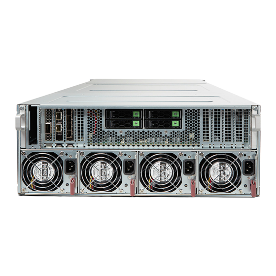
Appendix A 17.1.2 Server rear Figure 205: Server rear Slot for OCP module PCIe slots 7 - 10 PCIe slots 3 - 6 PSUs (4x) Up to four 2.5-inch HDDs or SSDs or dummy modules GX2570 M6 Upgrade and Maintenance Manual... -
Page 256: Server Interior
Appendix A 17.1.3 Server interior Server interior (CPU node) Figure 206: Server interior (CPU node) with air cooling Memory slots (32x) Riser module CPUs (2x) HDD cage System board HDD backplane Cross bar with 8x fans Front panel Upgrade and Maintenance Manual GX2570 M6... - Page 257 Appendix A Figure 207: Server interior (CPU node) with liquid cooling Memory slots (32x) Riser module CPUs with LC heat sinks (2x) HDD cage System board HDD backplane Cross bar with 8x fans Front panel GX2570 M6 Upgrade and Maintenance Manual...
- Page 258 Appendix A Server interior (GPU node) Figure 208: Server interior (GPU node) with air cooling GPUs (8x) Figure 209: Server interior (GPU node) with liquid cooling GPUs (8x) Upgrade and Maintenance Manual GX2570 M6...
- Page 259 Appendix A Server interior (switch board tray) Figure 210: Server interior (switch board tray) HDD cage (rear) PCIe slots for expansion cards HDD backplane (rear) Switch board GX2570 M6 Upgrade and Maintenance Manual...
-
Page 260: Connectors And Indicators
Appendix A 17.2 Connectors and indicators 17.2.1 System board 17.2.1.1 Connectors and indicators on the system board PRESS FIT JMB_E5 JMB_E6 JMB_E1 JMB_E3 JMB_E2 JMB_E4 JMB_AIOM CPU2 CPU1 BAR CODE IPMI CODE UM15 UM16 DATA CLK UM13 UM14 M.2-H1 JM2_1 JBT1 I-SATA0~3 JHDD_PWR1... - Page 261 Appendix A Pos. Print Component JVRM1/2 VRM SMB clock and data to BMC JUSB1 Front I/O panel standard USB 3.1 port FANA Fan header for liquid cooling pumps JPWR_Riser Power connector for riser card CMOS Battery JIPMB1 4-pin BMC external I C header FAN1 CPU/System fan...
- Page 262 Appendix A Pos. Print Component FANB Fan header for liquid cooling pumps JTPM1 Trusted Platform Module/Port 80 connector UM15/16 BIOS flash PRESS FIT JMB_E5 JMB_E6 JMB_E1 JMB_E2 JMB_E3 JMB_E4 JMB_AIOM CPU2 CPU1 BAR CODE IPMI CODE UM15 UM16 DATA CLK UM13 UM14 M.2-H1...
-
Page 263: Server Front
Appendix A Pos. Indicator Status Description LE3 Power System power off (power cable not connected) green on System power on LEDM1 BMC BMC controller cannot be Heartbeat detected or properly initiated. green on BMC initialing. flashing green BMC controller is working normally. -
Page 264: Indicators On The Front Panel
Appendix A 17.2.2.2 Indicators on the front panel Figure 214: Indicators on the front panel Power indicator LAN indicator Information indicator ID indicator Power indicator (1) Status Description Power is being supplied to the PSUs and the system is operating normally. Information indicator (2) Status Description... -
Page 265: Lan Indicators On The Front Panel
Appendix A ID indicator (4) Status Description blue on Identification has been activated by the ID button to locate the server in a rack environment. 17.2.2.3 LAN indicators on the front panel Figure 215: LAN indicators Link indicator (IPMI) Activity indicator (IPMI) Link indicator (1) Status Description... -
Page 266: Indicators On Hot-Plug Hdd/Ssd Modules
Appendix A 17.2.2.4 Indicators on hot-plug HDD/SSD modules Figure 216: Indicators on an HDD/SSD module Status indicator Activity indicator Status indicator (1) Status Description non-RAID configuration red on Failure of drive with Rapid Storage Technology enterprise (RSTe) support flashing red at Rebuild drive with RSTe support 1 Hz flashing red with... -
Page 267: Server Rear
Appendix A Activity indicator (2) Status Description blue on SAS/NVMe drive is installed. flashing blue Drive is being accessed. 17.2.3 Server rear 17.2.3.1 Indicators on hot-plug HDD/SSD modules Figure 217: Indicators on an HDD/SSD module Status indicator Activity indicator Status indicator (1) Status Description non-RAID configuration... -
Page 268: Indicator On Hot-Plug Psu
Appendix A Status Description flashing red at Identification of drive with RSTe support 4 Hz green on NVMe device can be removed safely flashing amber at Attention state, do not remove NVMe drive. 1 Hz Activity indicator (2) Status Description blue on SAS/NVMe drive is installed. -
Page 269: Acoustic Indicators
Appendix A PSU status indicator (1) Status Description flashing green The server is switched off, but mains voltage is present (standby mode). green on The server is switched on and operating properly. flashing amber An overload has been detected. The PSU is still running, but failure might be imminent. - Page 270 Appendix A # of Description Action Beep ▶ Check for the correct password and try Invalid password again. Make sure that the caps lock key is deactivated. No Console Input Booting will continue. devices or Output Serial console redirection is considered devices are found a console output device if enabled.
-
Page 271: Onboard Settings
Appendix A 17.3 Onboard settings PRESS FIT JMB_E5 JMB_E6 JMB_E1 JMB_E3 JMB_E2 JMB_E4 JMB_AIOM CPU2 CPU1 BAR CODE IPMI CODE UM15 UM16 DATA CLK UM13 UM14 M.2-H1 JM2_1 JBT1 I-SATA0~3 JHDD_PWR1 LEDM1 M.2-H2 I-SATA4~7 JM2_2 JHDD_PWR0 FAN8 FAN7 FAN6 FAN4 FAN3 FAN2 FAN5... -
Page 272: Minimum Startup Configuration
Appendix A 17.4 Minimum startup configuration Field Replaceable Units (FRU) If the server does not start up or other problems occur, it may be necessary to take the system down to its most basic configuration in order to isolate the defective component. - Page 273 Appendix A CAUTION ▶ Since the fan module is not included in the minimum startup configuration, the server must be shut down immediately after the diagnostic process is complete (POST phase has been passed). ▶ The minimum startup configuration must be used exclusively for diagnostic purposes by maintenance personnel, never in daily operation! GX2570 M6...
- Page 274 Appendix A Upgrade and Maintenance Manual GX2570 M6...
-
Page 275: Supplied Documents
The following documents are available in this appendix: ● "Cable plan for FUJITSU Server PRIMERGY GX2570 M6 Reference Manual" ● "List of Released Adapters incl. Installation sequence and priority" ● "Screw list for FUJITSU Server PRIMERGY GX2570 M6 Reference Manual" GX2570 M6 Upgrade and Maintenance Manual... - Page 276 System Name: PRIMERGY GX2570 M6 CPU sockets: #PCIe Slots of system: Riser Option support: y/n n Overview and properties of System PCI devices and slots System PCI Slot # PCI Slot attached CPU # CPU1 CPU1 CPU1 CPU1 CPU2 CPU2...
- Page 277 Cable Plan List of used cables Vendor Part number FUJITSU Part number Naming CBL-GNZ2-12105F-85 CA05973-7706 GENZ Cable CBL-GNZ2-1281F-85 CA05973-7707 GENZ Cable CBL-PWEX-1114-30 CA05973-7708 MicroFit Cable CBL-PWEX-1117-40 CA05973-7709 MiniFit Cable CBL-SAST-1238FLP-85 CA05973-7710 SlimlineLP x8 Cable CBL-SAST-1242-100 CA05973-7711 Slimline x4 Cable CBL-SAST-1258FLP-85...
- Page 278 Mother Board JSLIM4A JSLIM1A JSLIM4B JSLIM1B Riser Card JSLIM3A JSLIM2A (RSC-G-66G4) JSLIM3B JSLIM2B JPWR_RISER JPWR_RISER Mother Board (MBD-X12DGO-6) SAS #0-#3 CN10 SAS #4-#7 JHDD_PWR0 HD Backplane JHDD_PWR1 (BPN-NVME4- F418-B6S6) NVME#2 JSLIM1A NVME#3 HD Midplane NVMe0 NVMe1 NVME#4 (BPN-GPU-438G) NVME#5...
- Page 279 HD Midplane Fan adaptor Card JFAN_BOARD (AOM-438G-FAN-P) HD Midplane (BPN-GPU-438G) NVME#0 NVMe2 NVMe3 NVME#1 NVME#2 HD Backplane NVMe0 NVMe1 (BPN-NVME4- NVME#3 F418-B6S6) NVME#4 Mother Board NVME#5 JSLIM1A (MBD-X12DGO-6)
- Page 280 PCIE Board NVME #0/#1 NVMe1~2 HD Backplane PCIE Board NVME #2/#3 NVMe3~4 (BPN-NVME4- (AOM-SXM4-IO-P) HS119N-S4R) JPWR1 JPWR1...
- Page 281 AIOM adapter Card AIOM adapter Card JVGA1 VGA Port (AOM-438G-AIOM-P)
- Page 282 RAID Card SAS-MLC1 SATA #0-#3 RAID Card SAS-MLC2 HD Backplane (BPN-NVME4- F418-B6S6) SATA #4-#7...
- Page 283 Screw Type Torque Torque Notes Screw Head Screw Thread [Nomal] Tolerance FLAT #6-32*4L 3.5 ~ 4 in*lb FLAT #6-32*4L 3.5 ~ 4 in*lb BINDING #6-32*5L 6 ~ 8 in*lb BINDING #6-32*5L 6 ~ 8 in*lb 3.5 ~ 4 in*lb BINDING #6-32*8L 3.5 ~ 4 in*lb...