Motorola Wireless Broadband Routers WR850G User Manual
Motorola wireless broadband routers user guide
Hide thumbs
Also See for Wireless Broadband Routers WR850G:
- User manual (93 pages) ,
- Firmware release notes (14 pages) ,
- Troubleshooting (4 pages)
Table of Contents
Advertisement
Quick Links
Download this manual
See also:
Troubleshooting
Advertisement
Table of Contents
Troubleshooting

Related Manuals for Motorola Wireless Broadband Routers WR850G


Summary of Contents for Motorola Wireless Broadband Routers WR850G
-
Page 1: User Guide
User Guide WR850 Wireless Broadband Routers WR850GP and WR850G WR850G WR850GP... - Page 2 WARNING: TO PREVENT FIRE OR SHOCK HAZARD, DO NOT EXPOSE THIS PRODUCT TO RAIN OR MOISTURE. THE UNIT MUST NOT BE EXPOSED TO DRIPPING OR SPLASHING. DO NOT PLACE OBJECTS FILLED WITH LIQUIDS, SUCH AS VASES, ON THE UNIT. CAUTION: TO ENSURE REGULATORY COMPLIANCE, USE ONLY THE PROVIDED POWER AND INTERFACE CABLES. CAUTION: DO NOT OPEN THE UNIT.
-
Page 3: Fcc Declaration Of Conformity
Canadian Compliance This Class B digital apparatus meets all requirements of the Canadian Interference Causing Equipment Regulations. Cet appareil numérique de la classe B respects toutes les exigences du Règlement sur le matériel brouilleur du Canada. FCC Declaration of Conformity Motorola, Inc., Broadband Communications Sector, 101 Tournament Drive, Horsham, PA 19044, 1-215-323-1000, declares under sole responsibility that the WR850G and WR850GP, WA840G and WA840GP comply with 47 CFR Parts 2 and 15 of the FCC Rules as a Class B digital device. -
Page 4: Table Of Contents
Contents Section 1:Overview Understanding Your User Guide...1-3 Box Contents...1-3 Understanding Functions...1-4 Router ...1-4 LAN ...1-4 TCP/IP ...1-4 Static IP Address ...1-4 Dynamic IP Address ...1-5 DHCP Server ...1-5 Sample Home Network Diagram ...1-6 Positioning Your Router...1-6 Wireless Range...1-7 Technical Specifications ...1-7 Router Physical Description ...1-8 Back of Router ...1-8 Front of Router...1-9... - Page 5 Parental Control - URL Log...3-23 Configuring Networking Settings ...3-25 Configuring DHCP Server Settings ...3-25 Configuring the Router Host Name ...3-27 Configuring Network Router Settings...3-27 Configuring DDNS Settings ...3-29 Configuring NAT Settings ...3-30 Configuring Port Trigger Settings...3-31 Sample Port Trigger Entries...3-32 Configuring Virtual Server Settings ...3-33...
- Page 6 Contents Section 4:Troubleshooting Contact Us ...4-1 Hardware Solutions ...4-1 My computer is experiencing difficulty in connecting to the router...4-2 My broadband modem already uses a built-in router...4-2 Software Solutions...4-3 I would like to test to see if my Internet connection is live..4-3 I cannot access the Configuration Utility for the router.
-
Page 7: Section 1:Overview
Section 1:Overview Congratulations on purchasing the Motorola WR850GP Wireless Broadband Router or Motorola WR850G Wireless Broadband Router. The WR850 includes both an 802.11b/g wireless access point and a 4-port Ethernet router. So it is both wireless and wired, providing the foundation for a truly customized network full of options. - Page 8 Section 1 Your wireless router is really several products built into one router: Wireless Access Point – Connects your router to your laptop wirelessly and allows you to roam unfettered – Supports a multitude of devices that operate with both 802.11g and 802.11b wireless communication standards –...
-
Page 9: Understanding Your User Guide
Overview Understanding Your User Guide The User Guide is divided into the following sections: Overview Describes the router and its functions, the technology used, and the recommended methods for positioning the router. Installation It is assumed that you will use the Installation Wizard on the CD-ROM to set up your router. -
Page 10: Understanding Functions
Section 1 Overview Understanding Functions Before installing your wireless router, please take a few minutes to review the wireless networking functions described in this section. Router Generally, routers connect two networks together. The WR850 connects your home network with the Internet, which can be thought of as a very large network. Routers provide bandwidth security by keeping data out of your home network. -
Page 11: Dynamic Ip Address
Overview Section 1 Dynamic IP Address A dynamic IP address is a temporary IP number, dynamically or randomly generated by a DHCP server. The address lasts only as long as the server allots, usually in the space of a day or two. When the IP address expires, the client is automatically reassigned a new IP address, ensuring smooth communication. -
Page 12: Sample Home Network Diagram
Section 1 Sample Home Network Diagram Your wireless router serves as the centerpiece of your network, allowing you to share files, printers, and the Internet connection. A sample home network is shown below: The Internet communicates with the modem which in turn communicates with the router. The router acts as the gateway to your network;... -
Page 13: Wireless Range
Overview Wireless Range The following lists the expected wireless range of the router. This table is only a guide and coverage varies due to local conditions. Data Rate Open Area 54 Mbps Up to 100 ft (30m) 11 Mbps Up to 900 feet (275 m) 5.5 Mbps Up to 1300 feet (396 m) 2 or 1 Mbps... -
Page 14: Router Physical Description
Section 1 Router Physical Description The following sections describe the physical characteristics of your router. For instructions on installing your router, see Section 2: Installation. Back of Router The following illustration shows the WR850 back panel: Reset Power Feature Description Power The receptacle where you plug in the power adapter. -
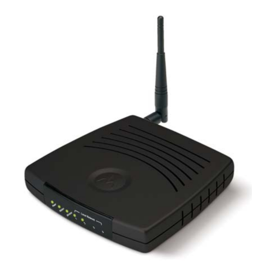
Page 15: Front Of Router
Overview Feature Description These four ports connect the router to your LAN or home network Ports 1-4 using Ethernet cables. This enables communication among clients, such as PCs or print servers, on the network. The LAN ports support either 10-BASE-T or 100-BASE-T transmission speeds as well as straight-through and crossover Ethernet cables. -
Page 16: Led Description
Section 1 LED Description The underlined items represent network activity. Condition 1 Power Blinking Blinking/OFF 2 Modem Blinking ON/Blinking ON/Blinking 3 Wireless ON/Blinking ON/Blinking 4 LAN (x4) ON/Blinking ON/Blinking 1-10 Color Status Green The device is powered on and operating normally. Green Firmware update is in progress. -
Page 17: Section 2:Installation
Section 2:Installation To get your network up and running: Set up your hardware. Insert the CD-ROM for product set up. Follow the prompts. If you prefer to set up the router’s software manually, refer to the Manual Software Setup found later in this section. The following sections provide detailed instructions for completing these tasks. -
Page 18: Router Physical Installation
Section 2 Router Physical Installation For the WR850GP, you can install the router horizontally or vertically. The WR850G can only be installed horizontally. Either router can also be mounted on a wall. Horizontal Installation Place the router in the desired location and follow the procedures below for connecting and configuring the router. -
Page 19: Wall Mount Installation
Installation Wall Mount Installation If you mount the router on the wall, you must: Position the router as specified by the local or national codes governing residential or business communications services. Follow all local standards for installing a network interface router/network interface device (NIU/NID). - Page 20 Section 2 To print the Wall Mounting Template, click the Print icon or choose Print from the File menu. In both the Pages from and to fields, enter the page number on which the Wall Mounting Template appears. Click OK. Measure the printed template with a ruler to ensure that it is the same size as the template on page 2-3.
- Page 21 Installation 10 Using a screwdriver, turn each screw until part of it protrudes from the wall, as shown: – There must be 4.0 mm (.16 inches) between the wall and the underside of the screw head. – The maximum distance from the wall to the top of the screw head is 7.6 mm (.3 in). 11 Remove the two plastic feet, nearest to the LED panel, from the bottom of the router to uncover the keyholes.
-
Page 22: Electrical Connection To Router
Section 2 Electrical Connection to Router Your router does not have an On/Off power switch and therefore will only be powered on by plugging in the power adapter: Connect the power adapter to the router’s Power port, found on the back of the router. Plug the power adapter into a grounded and surge-protected power outlet. -
Page 23: Wired Connection To Router
Installation Wired Connection to Router +12VDC If you are connecting your PC with an Ethernet cable to the router, your PC must be installed first with an Ethernet adapter. You need two Ethernet cables for this procedure, one cable to connect the router to the modem and one cable to connect a PC to the router. -
Page 24: Wireless Connection To Router
Section 2 Wireless Connection to Router WARNING! When first configuring your router, it is recommended that you have an Ethernet cable connected to the router. Performing the INITIAL configuration using a wireless connection is not secure and is not recommended. After you have finished the initial configuration of the router, your connection will be secure and you can safely use either a wired or wireless connection. -
Page 25: Configure Your Computers
Installation To connect the PC to the router through a wireless connection, verify the PC’s wireless adapter SSID (Service Set Identifier) is set to the router’s default setting of motorola appended with the last 3 characters of the Wireless MAC address (an example SSID: motorola 345) and that no encryption is enabled. -
Page 26: Configuring Windows 98Se And Me
Section 2 Configuring Windows 98SE and ME Click Start. Select Settings > Control Panel. Double-click Network. The Network window is displayed: On the Configuration tab, select the TCP/IP line the for the appropriate Ethernet adapter on your PC. There may be multiple adapters installed – choose only the one that is configured for your adapter. - Page 27 Installation Click Properties. The TCP/IP Properties window is displayed: Click the IP Address tab. Select Obtain an IP address automatically. Click OK. Click the Gateway tab and confirm that the Installed Gateway field is blank. 10 Click OK twice. Windows may ask for the Windows Installation disk. First check to see if the installation files are installed at c:\windows\options\cabs.
-
Page 28: Configuring Windows 2000
Section 2 Configuring Windows 2000 Click Start. Select Settings. Select Control Panel. Double-click Network and Dial-Up Connections. Double-click Local Area Connection. Click Properties. 2-12 Installation WR850... - Page 29 Installation The Local Area Properties window is displayed: Ensure the box next to Internet Protocol (TCP/IP) is selected. Click to highlight Internet Protocol (TCP/IP) and click Properties. WR850 Section 2 2-13...
- Page 30 Section 2 The Internet Protocol (TCP/IP) Properties window is displayed: Select Obtain an IP address automatically. Click OK twice to exit and save your settings. 10 Restart your computer to save your settings. 11 Proceed to the Configure Your Wireless Security Settings 2-14 Installation section to set up security.
-
Page 31: Configuring Windows Xp
Installation Configuring Windows XP This configuration assumes you have retained the default interface for Windows XP. If you are running the ‘Classic’ interface, please follow the instructions for Windows 2000. Click Start. Select Settings. Select Control Panel. Double-click Network and Dial-Up Connections. Double-click Local Area Connection. - Page 32 Section 2 The Local Area Properties window is displayed: Ensure the box next to Internet Protocol (TCP/IP) is selected. Click to highlight Internet Protocol (TCP/IP) and click Properties. 2-16 Installation WR850...
- Page 33 Installation The Internet Protocol (TCP/IP) Properties window is displayed: Click Obtain an IP address automatically. Click OK twice to exit and save your settings. Proceed to the Configure Your Wireless Security Settings security settings. WR850 Section 2 section to set up the 2-17...
-
Page 34: Configure Your Wireless Security Settings
Section 2 Configure Your Wireless Security Settings Before your router can communicate securely with your computer, you must configure your wireless security settings. Failure to configure these settings properly could compromise your network to wireless hackers. Logging In WARNING! When first configuring your router, it is recommended that you have an Ethernet cable connected to the router. -
Page 35: Wireless Security Setup
Installation Wireless Security Setup To set up the correct security protocols for your router: Click Control Panel > Device Security. In the Login User ID field, enter your User ID. Create an ID that contains multiple case- sensitive characters as well as numbers. It cannot be longer than 64 bytes. In the Login Password field, enter your Login Password. -
Page 36: Configure Your Basic Internet Settings
Section 2 Configure Your Basic Internet Settings The following settings configure your router for accessing the Internet. Detailed descriptions for using the web-based utility follow this section. Log into the router’s Configuration Utility. The Internet > Basic screen is displayed. Select the Connection Mode your ISP has indicated you need to use. -
Page 37: Static Ip
Installation Static IP If you are required to use a permanent IP address for connecting to the Internet, then select Static Assigned. Your ISP informs you if this is the connection to use. From Connection Mode, select Static Assigned. In the IP address field, enter the IP address supplied by your ISP. In the Subnet Mask field, enter the Subnet Mask supplied by your ISP. -
Page 38: Section 3:Configuration
Section 3:Configuration Use the information in this section to modify the router’s settings. For example you can customize features for your home network, change settings such as your user name or password, or view the status of the network. The screenshots seen here are intended for reference only; your version of firmware may differ slightly. -
Page 39: Navigation
Section 3 Navigation Each of the following subsections describe the components of the router’s Configuration Utility which is accessible from a web browser. These sections include: • Internet • Wireless • Parental Control • Networking • Control Panel To navigate, click on a major section and then the associated subsection. For example, to adjust the time setting, click CONTROL PANEL on the left, then the TIME tab at top on the right. -
Page 40: Configuring Internet Settings
Configuration Configuring Internet Settings The Internet Settings screens enable you to configure your Internet settings: Basic Advanced Network Diagnostic Basic Internet Settings After logging into the Configuration Utility, the Internet - Basic screen is displayed. It allows you to adjust basic settings for the router’s Internet options. You can also access this screen by clicking Internet on the login screen. - Page 41 Section 3 Field or Button Description WAN Interface Displays the status of the router: Active Inactive Disabled The WAN interface has been disabled. To enable the Connection The router supports four connection modes for acquiring its IP Mode configuration settings of the WAN interface: Cable Modem (DHCP) DSL Modem (PPPoE) Static Assigned...
- Page 42 Configuration Field or Button Description Default Is automatically displayed or manually entered from information Gateway provided by your ISP. Select Yes to obtain the DNS information automatically, or No to enter Obtain DNS Server Address the information manually. Automatically Primary DNS Is automatically displayed or manually entered from information provided by your ISP.
- Page 43 Section 3 Field or Button Description PPP Service Is either automatically displayed or manually entered from information Name provided by your ISP. Click to enable PPP Idle Time. PPP Idle Timer PPP Idle Time Enter the amount of time to elapse before the router automatically breaks the connection to the Internet.
-
Page 44: Advanced Internet Settings
Configuration Advanced Internet Settings The Internet – Advanced screen allows you to adjust additional Internet settings. To access the screen, click Internet > Advanced. Field or Button Description WAN Interface Check to enable the link to the Internet. Disabling this feature disconnects your Internet connection. -
Page 45: Troubleshooting Your Network Connections
Section 3 Field or Button Description Learned MAC Displays the MAC addresses (wired or wireless devices) the router has Address already recorded. If you wish to use one of the displayed MAC addresses: Click the address number. The number automatically appears in the Cloned WAN MAC Address field. -
Page 46: Configuring Wireless Network Settings
Configuration Field or Button Description DNS Lookup Finds the IP address of a website name. For example, if you enter www.motorola.com, a DNS server returns the IP address of Motorola. To use any of these functions: Enter a Host Name or IP Address in the Ping, Trace Route, or DNS Lookup fields. Click Ping, Trace Route, or DNS Lookup to activate the function. - Page 47 Section 3 Field or Button Description Network Name Enter a name of no more than 32 alphanumeric characters. This (SSID) SSID must be entered on every wireless device on your wireless network to communicate with the router. The default SSID is motorola XXX, where XXX are the last 3 characters of your Wireless MAC address, found on the label on the bottom of the unit.
-
Page 48: Configuring Wireless Security Settings
Configuration Field or Button Description Wireless MAC Displays the Wireless MAC address of the unit. This is not the same Address as the WAN MAC address. Click to save your settings. Apply Cancel Click to cancel any changes. Configuring Wireless Security Settings The Wireless Security screen allows you to configure the security settings for your router. - Page 49 Section 3 Field Description Extended Service Set (ESS). Authentication establishes either an open Authentication or secure verification of communication with an access point (AP). This setting does not encrypt your transmission. The options are: Open System Pre-Shared Key (PSK) WPA-PSK WPA-PSK is recommended for home users not using a RADIUS server.
- Page 50 Configuration Field Description 802.1X mode Can only be enabled when the ESS Authorization is set to Open or PSK and either WEP64 or WEP128 is selected (see the Encryption Status field). During the Authentication process, the server verifies the identity of the client attempting to connect to the network. When WPA or WPA-PSK is selected in the ESS Authentication field, this option is automatically selected.
- Page 51 Section 3 Field Description Key Index Use the drop-down list here to select one of the Key Content fields below (Key 1, Key 2, etc). A maximum of four different Keys (1, 2, 3, or 4) are available. The number of keys is determined by what is selected in the ESS Authentication and Encryption Status fields.
- Page 52 Configuration Field Description RADIUS Shared Type the RADIUS password in this field. Secret Re-type the RADIUS password in this field. RADIUS Shared Secret Confirmation Wireless MAC Enables you to control which device accesses your wireless network Access Control based upon their MAC address. The default is disabled. The options List are: Enable...
-
Page 53: Monitoring Wireless Access Points
Section 3 Field Description Apply Click to save your settings. Click to cancel any changes. Cancel Monitoring Wireless Access Points The Site Monitor screen displays information about wireless Access Points (AP) and stations. To access the screen, click Wireless > Site Monitor. The Station Association List identifies only those stations that are connected to your wireless router. - Page 54 Configuration The Site Survey displays information about other APs in the area. Field Description Scan Click Scan to search for more APs or clients. SSID Displays the SSID of the device found. MAC Address Displays the MAC address of the device found. Channel Displays the channel upon which the device is broadcasting.
-
Page 55: Advanced Wireless Configuration
Section 3 Advanced Wireless Configuration The Wireless – Advanced screen allows you to turn your wireless network on and off and adjust wireless parameters. Generally, these settings should remain at their default values. To access the screen, click Wireless > Advanced. Field Description Allows you to turn on and off the wireless feature. - Page 56 Configuration Field Description Fragmentation Allows you to set the size at which packets are fragmented and Threshold transmitted a piece at a time instead of all at once. The setting must be within the range of 256 to 2346 bytes. The default is 2346.
- Page 57 Section 3 Field Description 11g Protection Ensures that your wireless router does not interfere with neighbor Mode networks. 802.11g networks cause “collisions” on 802.11b networks, so the Protection Mode forces the 802.11g network to negotiate around the 802.11b network. The options are: Disable Auto WDS Mode...
-
Page 58: Configuring Parental Control Settings
Configuration Configuring Parental Control Settings Parental Control settings allow you to tailor the type of content your router can access. Content Policies allow you to specify the websites or keyword searches users can access. Up to ten policies can be created, each of which can be customized for specific time periods and associated with any of the PCs your router supports. - Page 59 Section 3 Field Description Content Policy Enables or disables the Content Policy feature. The default is disabled. Policy Number The policy number you assign. Policy Name The name of the policy, up to 32 characters. You can enter up to ten different policies, tied to the Policy Number.
-
Page 60: Parental Control - Url Log
Configuration To create a policy: Enter a name in the Policy Name field. Decide if you want to Allow or Deny a URL (the address of a website). You can add more than one URL, separated by semicolons. The final entry must end with a semicolon. - Page 61 Section 3 Field Description Visited URL Displays the URL (website) that the PC has accessed. LAN IP Displays the IP address of the device on your network (LAN or Wireless) that accessed the Internet. LAN MAC Displays the PC’s MAC address. Address LAN Host Name Displays the PC’s Host Name.
-
Page 62: Configuring Networking Settings
Configuration Configuring Networking Settings The Networking screens allow you to configure your router to work with your Local Area Network (LAN). You should not need to make any changes to these settings. The following screens are available in Networking: DHCP Server DNS Proxy Routing DDNS... - Page 63 Section 3 Field Description LAN MAC Displays the LAN MAC address of the router. This field cannot be Address edited. LAN Private IP Enables you to create your own private IP network. Enter an IP address string that you will use for your network. Because it is a private network, your router gives you the ability to choose any string you prefer.
-
Page 64: Configuring The Router Host Name
Click to save your changes. Cancel Click to cancel your changes. Configuring Network Router Settings From the Networking – Routing screen, you can define up to 20 static routes that specify the Destination IP, Subnet Mask, Gateway, Interface, and Metric (how many “hops” the router can make). - Page 65 Section 3 To access the screen, click Networking > Routing. Field Description RIP V1 Enables or disables RIPv1. The default is disabled. RIP V2 Enables or disables RIPv2. The default is disabled. Routing Table To add a Routing Entry: Entry List Select a Destination IP number, (the client’s Routing IP address).
-
Page 66: Configuring Ddns Settings
Configuration Configuring DDNS Settings The router supports the Dynamic Domain Name System (DDNS) feature. DDNS enables you to assign a fixed host and domain name to a dynamic Internet IP address. It is useful when you are hosting your own web server, FTP server, or another server behind the router. -
Page 67: Configuring Nat Settings
Section 3 Configuring NAT Settings The Networking – NAT screen allows you to add another level of security to your Internet activity and online games. Network Address Translation (NAT) translates the multiple IP addresses on a private LAN to one public address that is sent out to the Internet by your ISP. -
Page 68: Configuring Port Trigger Settings
Configuration Field Description ICMP Session Enter the Internet Control Message Protocol (ICMP) Session Idle Idle Time Time, which is the amount of time an ICMP session will remain idle before timing out. ICMP is used for error, problem, and informational messages sent between IP hosts and gateways. -
Page 69: Sample Port Trigger Entries
Section 3 To add a Port Trigger entry: Enter the name of the application in the Port Trigger Name field. There is a limit of 32 characters for the name. Click enable if you wish the port trigger to become active immediately. Otherwise, you can save the information and enable it at later date. -
Page 70: Configuring Virtual Server Settings
Configuration Configuring Virtual Server Settings The Virtual Server sets up an automatic inbound forwarding mechanism for services running on your computer, such as web servers, email servers, or other specialized applications. You must configure your server with a static IP address to use this service. To access the screen, click Networking >... -
Page 71: Configuring The Firewall
Section 3 To update or remove an entry, select it and then click Edit or Remove to perform the action. Configuring the Firewall The firewall on your router shields your network from the Internet by examining network packets (units of data sent on a network) before they are forwarded to your router. The Networking –... - Page 72 Configuration To add a Packet Filter entry: Enter a descriptive name in the Packet Filter Name field. From the Filter Action drop-down list, select Allow or Deny. Allow permits data that meets the criteria selected. Deny blocks the data that meets the selected criteria. From the Packet Direction drop-down list, select Inbound or Outbound, based on whether you want to monitor incoming or outgoing packets.
-
Page 73: Configuring Control Panel Settings
Section 3 Configuring Control Panel Settings The Control Panel screens enable administrative maintenance for your router, such as changing your login User ID/Password, updating your firmware, or backing up your configuration. The following screens are available in Control Panel: Device Security Firmware Update Configuration Data Time... -
Page 74: Updating Firmware
Configuration Field Description WAN Web Login Enables you to log into the router from the Internet. Click to enable. The default is disabled. WAN Web Login Enables you to specify different ports on the router to allow remote Port login. The default is 8080. Login Idle Time Sets the amount of idle time (no actions occur) that elapses before the router automatically logs off the user. -
Page 75: Saving And Restoring Configuration Settings
Section 3 Saving and Restoring Configuration Settings This Configuration Data screen allows you to save and restore your router’s configuration settings. You are also able to reset the router to its factory default settings. To access the screen, click Control Panel > Configuration Data. To reset the router to its original configuration;... -
Page 76: Configuring Time Settings
Configuration Configuring Time Settings The Time screen enables you to configure time settings. To access the screen, click Control Panel > Time. Field Description Current Time Displays the current time. Time Zone Select your local time zone. The default is EST. Auto Daylight If you want to automatically adjust for Daylight Savings Time, check to Adjust... -
Page 77: Configuring Upnp
Section 3 Configuring UPnP The UPnP screen allows you to enable/disable Universal Plug and Play (UPnP). UPnP allows an application to smoothly map to the router. To access the screen, click Control Panel > UPnP. Field Description LAN UPnP Device Click to enable this feature. -
Page 78: Section 4:Troubleshooting
Section 4:Troubleshooting This section details possible solutions to common problems that might occur in using the router. Contact Us If you are unable to locate a solution here, please access our website at www.motorola.com/broadband/networking 7 days a week, 24 hours a day at 1-877-466-8646. Hardware Solutions My computer is experiencing difficulty connecting to the wireless network. -
Page 79: My Computer Is Experiencing Difficulty In Connecting To The Router
Section 4 My computer is experiencing difficulty in connecting to the router. Ensure that all of your cabling connections are firmly connected. This includes the cables from the wall to your modem, between the router and modem, and, if available, from the router to your PC. -
Page 80: Software Solutions
Troubleshooting Software Solutions I would like to test to see if my Internet connection is live. Use the ping command to test the connection. Before attempting, ensure that Obtain an IP address automatically has been selected in the computer’s settings and that you have an IP address assigned. -
Page 81: I Cannot Access The Configuration Utility For The Router
Section 4 I cannot access the Configuration Utility for the router. Verify your Ethernet connection to the router. Verify that the IP address of the PC being used to configure the router is on the same network as the router’s configuration IP address. The IP address of your network adapter must be on the same network and not a duplicate of any others on the network (for example: 192.168.10.10 and using a subnet mask of 255.255.255.0 can be used to login to the router’s default IP address of... -
Page 82: What If Pass Phrase Isn't Supported? What Do I Enter For My Security
Troubleshooting Section 4 What if Pass Phrase isn’t supported? What do I enter for my security? Some wireless cards do not support Pass Phrase or Motorola’s Pass Phrase algorithm, which means you have to enter the entire Key Content found in the appropriate Key field. So, using the WEP example from above if using Key 1, you would enter 03F32226A…etc. -
Page 83: Section 5:Glossary
Section 5:Glossary Access Point (AP) A device that provides wireless LAN connectivity to wireless clients (stations). The WR850 acts as a wireless access point. Adapter A device or card that connects a computer, printer, or other peripheral device to the network or to some other device. A wireless adapter connects a computer to the wireless LAN. - Page 84 Section 5 Basic Service Set. A configuration of Access Points that communicate with each other without resorting any infrastructure. Also known as Ad-Hoc networks. Also see ESS. Client In a client/server architecture, a client is a computer that requests files or services such as file transfer, remote login, or printing from the server.
- Page 85 Glossary DHCP A Dynamic Host Configuration Protocol server dynamically assigns IP addresses to client hosts on an IP network. DHCP eliminates the need to manually assign static IP addresses by “leasing” an IP address and subnet mask to each client. It enables the automatic reuse of unused IP addresses: The WR850 is simultaneously a DHCP client and a DHCP server.
- Page 86 Section 5 DSSS Direct-Sequence Spread Spectrum. DSSS is a transmission technology used in WLAN transmissions where a data signal at the sending station is combined with a higher data rate bit sequence, or chipping code, that divides the user data according to a spreading ratio.
- Page 87 Glossary File Transfer Protocol is a standard Internet protocol for exchanging files between computers. FTP is commonly used to download programs and other files to a computer from web pages on Internet servers. Gateway A device that enables communication between networks using different protocols.
- Page 88 Section 5 IEEE The Institute of Electrical and Electronics Engineers, Inc. (http://www.ieee.org) is an organization that produces standards, technical papers, and symposiums for the electrical and electronic industries and is accredited by ANSI. 802.11b and 802.11g are examples of standards they have produced. Internet A worldwide collection of interconnected networks using TCP/IP.
- Page 89 Glossary One megabyte; equals 1,024 x 1,024 bytes, 1,024 kilobytes, or about 8 million bits. Mbps Million bits per second (megabits per second). A rate of data transfer. The Maximum Transmission Unit is the largest amount of data that can be transmitted in one discrete message on a given physical network.
- Page 90 Section 5 PCMCIA The Personal Computer Memory Card International Association sets international standards for connecting peripherals to portable computers. Laptop computers typically have a PCMCIA slot that can hold one or two PC Cards to provide features such as Ethernet connectivity. ping A network function that tests host reachability by sending a small packet to the host and waiting for a reply.
- Page 91 Glossary RJ-11 The most common type of connector for household or office phones. RJ-45 An 8-pin modular connector; the most common connector type for 10Base-T or 100Base-T Ethernet networks. Roaming The ability to transfer your wireless session from one AP to another AP seamlessly.
- Page 92 Section 5 Static IP Address An IP address that is permanently assigned to a host. Normally, a static IP address must be assigned manually. The opposite of Dynamic IP Address. Station IEEE 802.11b term for wireless client. Subscriber A user who accesses television, data, or other services from a service provider.
- Page 93 Glossary Tunnel To place packets inside other packets to send over a network. The protocol of the enclosing packet is understood by each endpoint, or tunnel interface, where the packet enters and exits the network. VPNs rely on tunneling to create a secure network. Tunneling requires the following protocol types: A carrier protocol, such as TCP, used by the network that the data travels over...
- Page 94 Section 5 A virtual private network is a private network that uses “virtual” connections (tunnels) routed over a public network (usually the Internet) to provide a secure and fast connection; usually to users working remotely at home or in small branch offices. A VPN connection provides security and performance similar to a dedicated link (for example, a leased line), but at much lower cost.
- Page 95 Visit our website at: www.motorola.com/broadband 516587-001 7/04 MGBI...