
Related Manuals for Kenwood TH-F7A


Summary of Contents for Kenwood TH-F7A
- Page 1 INSTRUCTION MANUAL FM DUAL BANDER TH-F7 144/ 430 MHz FM DUAL BANDER TH-F7A © B62-1899-00 (M) 09 08 07 06 05 04 03 02 01 00...
-
Page 2: Features
Do not expose the transceiver to long periods of THANK YOU direct sunlight nor place the transceiver close to heating appliances. Thank you for choosing this KENWOOD TH-F7A transceiver. It has been developed by a team of • Do not place the transceiver in excessively dusty... -
Page 3: Table Of Contents
CONTENTS THANK YOU ............. i CHAPTER 6 MEMORY CHANNELS FEATURES ............... i SIMPLEX & REPEATER OR ODD-SPLIT MEMORY PRECAUTIONS ............i CHANNEL? ............15 SUPPLIED ACCESSORIES ........i STORING SIMPLEX FREQUENCIES OR WRITING CONVENTIONS FOLLOWED ....i STANDARD REPEATER FREQUENCIES ..15 CONTENTS ............. - Page 4 DCS ............... 28 VOX ON BUSY ..........40 USING DCS ............28 CHAPTER 12 OPTIONAL ACCESSORIES SELECTING A DCS CODE ........ 28 DCS CODE ID SCAN ........29 OPTIONAL ACCESSORIES ........41 CHAPTER 9 DTMF FUNCTIONS CHAPTER 13 INTERFACING TO PERIPHERALS MANUAL DIALING..........
-
Page 5: Chapter 1 Preparation
PREPARATION 2 Slide the battery pack along the back of the INSTALLING ALKALINE BATTERIES transceiver until the release latch on the top of the 1 To open the battery case (BT-13), push the locking transceiver locks the battery pack in place. tab in, then pull the cover back. -
Page 6: Connecting To A Regulated Power Supply
1 PREPARATION 3 Plug the charger into an AC wall outlet. CONNECTING TO A REGULATED POWER • Charging starts and 2 LEDs on the top panel SUPPLY lights orange. To connect the transceiver to an appropriate 4 It takes approximately 6.5 hours to charge an regulated power supply, use an optional PG-2W empty PB-42L Li-ion battery pack. -
Page 7: Chapter 2 Your First Qso
] (POWER) briefly to switch the transceiver power ON. • A high pitched double beep sounds and then “KENWOOD” and “HELLO !!” appear momentarily. The various indicators and 2 frequencies appear on the LCD. • The transceiver stores the parameters when it is turned OFF. -
Page 8: Chapter 3 Getting Acquainted
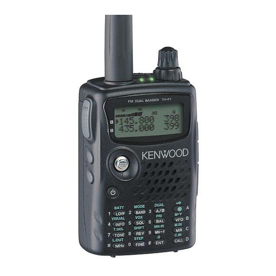
GETTING ACQUAINTED KEYS AND CONTROLS Antenna Tuning Control VOL Control FM DUAL BANDER TH-F7 PTT switch Display SP/MIC jack LAMP Key Multi-scroll Speaker/ Mic. MONI Key Power Switch DC IN jack Keypad Battery release A/ B-band status LEDs Green : Busy : Transmitting Orange: Charging... -
Page 9: Display
3 GETTING ACQUAINTED DISPLAY 19 20 q EL Appears when the transmit output power is set to Low Appears when the Lock function is ON {page 36}. (“L”) or Economic Low (“EL”) {pages 7, 39}. Appears when the function key is pressed. Appears when the transmit output power is set to High (“H”) {pages 7, 39}. -
Page 10: Basic Operation Switching Power On/ Off
3 GETTING ACQUAINTED • The higher the level, the stronger the signals BASIC OPERATION must be, to receive. SWITCHING POWER ON/ OFF • 6 different levels can be set 1 Press [ ] (POWER) briefly to switch the (-- -- -- -- --: level 0 ~ || || || || ||: level 5). transceiver power ON. -
Page 11: Transmitting
3 GETTING ACQUAINTED TRANSMITTING ■ MHz Mode 1 To transmit, hold the transceiver approximately If the desired operating frequency is far away from 5 cm (2 inches) from your mouth, then press and the current frequency, it is quicker to use the MHz hold the PTT switch and speak into the tuning mode. - Page 12 3 GETTING ACQUAINTED Example 6 Example 1 (100 MHz < f < 1000 MHz) To enter 810 kHz (B-band only): To enter 438.320 MHz: Key in Display Key in Display [ENT] – – – – – – [ENT] – – – – – – 0 –...
-
Page 13: Chapter 4 Menu Setup
MENU SETUP WHAT IS A MENU? SELECTING A MENU LANGUAGE You can select either English or Japanese (Katakana) Many functions on this transceiver are selected or configured via a software-controlled Menu, rather for the menu description. To switch the language: than through the physical controls of the transceiver. - Page 14 4 MENU SETUP . f e i t c o i t t l u — i r t o i t e l i n i t h t i c i t o i t . n i .
-
Page 15: Alphabetical Function List
4 MENU SETUP ALPHABETICAL FUNCTION LIST o i t t l u . f e . n i — — —... -
Page 16: Chapter 5 Operating Through Repeaters
“+” or “–” appears, indicating which offset consult your local repeater reference. direction is selected. • To program –7.6 MHz offset on the TH-F7A (430 MHz only), repeatedly press [F], [REV] until “ ” appears. If the offset transmit frequency falls outside the allowable range, transmitting is inhibited. -
Page 17: Activating Tone Function
5 OPERATING THROUGH REPEATERS ■ Activating Tone Function AUTOMATIC REPEATER OFFSET Press [TONE] to switch the Tone function ON (or This function automatically selects an offset direction, OFF). according to the frequency that you select on the 2 m band. The transceiver is programmed for offset •... -
Page 18: Reverse Function
5 OPERATING THROUGH REPEATERS REVERSE FUNCTION TONE FREQ. ID SCAN The reverse function exchanges a separate receive This function scans through all tone frequencies to and transmit frequency. So, while using a repeater, identify the incoming tone frequency on a received you can manually check the strength of a signal that signal. -
Page 19: Chapter 6 Memory Channels
MEMORY CHANNELS In memory channels, you can store frequencies and STORING SIMPLEX FREQUENCIES OR related data that you often use. Then you need not STANDARD REPEATER FREQUENCIES reprogram those data every time. You can quickly recall a programmed channel through simple 1 Press [VFO]. -
Page 20: Recalling A Memory Channel
6 MEMORY CHANNELS ◆ When you revise only the transmission frequency for the odd- CLEARING A MEMORY CHANNEL split channel, the frequency step size must be the same as the original odd-split channel memory data. To clear an individual memory channel: 1 Recall the memory channel you want to erase. -
Page 21: Naming A Memory Channel
6 MEMORY CHANNELS NAMING A MEMORY CHANNEL Available Characters Using the Tuning Control Available Characters You can name memory channels using up to 8 alphanumeric characters. When you recall a named memory channel, its name appears on the display in place of the stored frequency. -
Page 22: Memory Channel Groups
6 MEMORY CHANNELS MEMORY CHANNEL GROUPS ERASING MEMORY CHANNELS USING MEMORY GROUP DELETE FUNCTION 400 memory channels have been divided into 8 groups of 50. Group 0 contains memory channel Instead of erasing each unnecessary channel one by numbers 0 ~ 49, group 1 is 50 ~ 99, group 2 is 100 ~ one, you can erase an entire group of memory 149, and so on. -
Page 23: Call Channel
6 MEMORY CHANNELS CALL CHANNEL ➡ ➡ The Call channel can be recalled instantly no matter what frequency the transceiver is operating ➡ on. For instance, you may use the Call channel as ➡ an emergency channel within your group. In this case, the Call Scan {page 24} will be useful. -
Page 24: Information Channels
6 MEMORY CHANNELS INFORMATION CHANNELS CHANNEL DISPLAY 10 Information channels are available for storing While in this mode, the transceiver displays only radio broadcasting service frequencies, such as memory channel numbers (or memory names if community FM broadcasting stations. For your stored) instead of frequencies. -
Page 25: Chapter 7 Scan
SCAN Scan is a useful function for hands-off monitoring of NORMAL SCAN your favorite frequencies. By becoming comfortable with all types of Scan, you will increase your operating When you are operating the transceiver in VFO mode, efficiency. 3 types of scanning are available: Band Scan, Program Scan, and MHz Scan. -
Page 26: Program Scan
7 SCAN PROGRAM SCAN ◆ To perform the Program Scan, the following conditions must be met. Otherwise, the Band scan starts {page 21}. You can limit the scanning frequency range. There • The upper and lower limit frequencies are in the same frequency band. -
Page 27: Memory Scan
7 SCAN ■ Memory Group Link MEMORY SCAN Although the 400 memory channels are divided Memory Scan monitors all memory channels in which into 8 groups {page 18}, you may sometimes want you have stored frequencies (All-Channel Scan) or to scan two or more groups. In this case, use the only a desired group of memory channels (Group Memory Group Link function. -
Page 28: Call Scan
7 SCAN CALL SCAN PRIORITY SCAN A Call channel can be stored for each amateur radio You may sometimes want to check your favorite band, such as the 2 m, 70 cm bands {page 19}. You frequency activities while monitoring the A and can monitor one of these Call channels and the B-bands. -
Page 29: Information Channel Scan
7 SCAN VISUAL SCAN Note: ◆ The signal being received on the B-band may become While you are receiving, Visual Scan allows you to intermittent because the Priority Scan uses the B-band receiver to check the priority channel(s) activities. monitor frequencies near the current operating ◆... -
Page 30: Using Visual Scan (Memory Channel)
7 SCAN USING VISUAL SCAN (MEMORY CHANNEL) Note: ◆ The Program Scan memories (L0/U0 ~ L9/U9) and Priority 1 Press [MR] to enter Memory Recall mode. channels (Pr1 and Pr2) cannot be locked out. ◆ Even if a memory channel is locked out, you can perform the 2 Turn the Tuning control or press [ ]/ [ ] to select Call Scan {page 24} between the Call channel and memory your desired center memory channel. -
Page 31: Chapter 8 Selective Call
SELECTIVE CALL CTCSS and DCS CTCSS You may sometimes want to hear calls from only A CTCSS tone is a sub-audible tone and is selectable specific persons or groups. In this case, use the from among the 42 tone frequencies listed in the selective call function. -
Page 32: Ctcss Freq. Id Scan
8 SELECTIVE CALL CTCSS FREQ. ID SCAN This function scans through all CTCSS frequencies to DCS is similar to CTCSS. However, instead of using identify the incoming CTCSS frequency on the an analog audio tone, it uses a continuous sub- received signal. -
Page 33: Dcs Code Id Scan
8 SELECTIVE CALL DCS CODE ID SCAN This function scans through all DCS codes to identify the incoming DCS code on the received signal. You may find this useful when you cannot recall the DCS code that the other persons in your group are using. 1 While in DCS mode, press [F], [TONE] (1 s) to start the DCS Code ID Scan function. -
Page 34: Chapter 9 Dtmf Functions
DTMF FUNCTIONS The keys on the keypad also function as DTMF keys; AUTOMATIC DIALER the 12 keys found on a touch-tone phone plus 4 additional keys (A, B, C, D). This transceiver also If you use the 10 dedicated memory channels to store provides 10 dedicated DTMF memory channels. -
Page 35: Transmitting A Stored Dtmf Number
9 DTMF FUNCTIONS • Pressing [ ] after selecting the 8th digit ADJUSTING THE DTMF TONE TRANSMISSION completes the programming. SPEED • To complete programming a name with less This transceiver allows you to configure the DTMF than 8 digits, press [MNU] or [ ] twice. number transmission speed between Fast (default) •... -
Page 36: Chapter 10 Utilizing The B-Band
UTILIZING THE B-BAND ■ B-band Frequency Coverage ABOUT THE B-BAND Usually you can communicate with other amateur radio stations using A-band frequencies for receiving and transmitting. This transceiver also features another receiver in addition to the A-band transceiver. The frequency for the B-band appears on the bottom part of the display. -
Page 37: Selecting A Mode For The B-Band
10 UTILIZING THE B-BAND SELECTING A MODE FOR THE B-BAND FINE TUNING When using the B-band receiver, the following When you operate the B-band in LSB, USB, CW, or receiving mode is available. AM mode, you can turn the Fine Tuning function ON. You can further configure the Fine Tuning frequency step size from 33 Hz, 100 Hz (default), 500 Hz, or i v i... -
Page 38: Chapter 11 Operator Conveniences
OPERATOR CONVENIENCES APO (Auto Power OFF) BATTERY LIFE Before you operate the transceiver outside using a The transceiver switches OFF automatically if no battery pack, it is important to know how long you can keys or controls are pressed or adjusted, and no operate the transceiver. -
Page 39: Battery Saver
11 OPERATOR CONVENIENCES 3 Press [ ] or [MNU]. Note: Use the PB-42L (Lithium battery pack) within the temperature range of –10°C ~ 50°C. 4 Turn the Tuning control or press [ ]/ [ ] to select “OFF”. BATTERY SAVER 5 Press [ ] or [MNU] to store the setting. -
Page 40: Lamp
11 OPERATOR CONVENIENCES The default step size for the amateur radio bands are • The following keys cannot be locked: as follows. [LAMP], [MONI], [SQL], [PTT], [F] (1 s), ] (POWER) and [F] then [LAMP]. 2 Press [F] (1 s) to unlock the keys. Note: ◆... -
Page 41: Monitor
11 OPERATOR CONVENIENCES Note: ◆ When you select “9600” bps for the Menu No. 28 (PACKET) , the operating mode temporarily returns to a normal FM mode. - < f > ◆ You can store the narrow band FM operation status to each amateur radio band. -
Page 42: Single Band Operation
11 OPERATOR CONVENIENCES Menu No. 4 (PROG VFO). TONE ALERT • The current programmable frequency range for Tone Alert provides an audible alarm when signals the band appears. are received on the frequency you are monitoring. In addition, it shows the number of hours and minutes elapsed after signals have been received. -
Page 43: Tx Power
11 OPERATOR CONVENIENCES TX POWER Note: ◆ If TNC is selected for Menu No. 9 (SP/MIC JACK), the To change the transmission output power: squelch status (REM/ SQ) changes based on your volume balance settings {pages 42, 43}. Press [LOW]. ◆... -
Page 44: Vox Delay Time
11 OPERATOR CONVENIENCES 2 While speaking into the microphone using your normal tone of voice, adjust the VOX Gain by pressing [ ]/ [ ] until the transceiver reliably switches to transmit mode each time you speak. • The setting should not allow background noise to switch the transceiver to transmit mode. -
Page 45: Optional Accessories
OPTIONAL ACCESSORIES BT-13 EMC-3 HMC-3 KHS-21 Battery Case (4 AA/ LR6) Clip Microphone with Headset (with VOX/ PTT) Headset Earphone PB-42L PG-2W PG-3J SMC-32 Li-ion Battery Pack DC Power Cable Cigarette Lighter Power Speaker Microphone (7.4 V, 1550 mAh) Cable SMC-33 SMC-34 Speaker Microphone (with... -
Page 46: Chapter 13 Interfacing To Peripherals
SELECTING SP/MIC JACK FUNCTION 2.5 mm Plug Speaker Unless you connect the transceiver to a TNC or PC, TH-F7A the default setting of the SP/MIC jack function (Menu No. 9), “SP/MIC” works fine. However, if you want to 3.5 mm Plug... - Page 47 PC, access Menu No. 9 and select “PC”. PC with a serial (COM) port PC Interface cable TH-F7A For your information, the following diagram shows how the TH-F7A communicates to the PC using a serial (COM) port. Level converter COM port TH-F7A 2.5 mm...
-
Page 48: Chapter 14 Troubleshooting
You may return your transceiver for service to the authorized KENWOOD dealer from whom you purchased it or any authorized KENWOOD service center. A copy of the service report will be returned with the transceiver. Please do not send subassemblies or printed circuit boards. -
Page 49: Troubleshooting
14 TROUBLESHOOTING TROUBLESHOOTING The problems described in the following table are commonly encountered operational malfunctions. These types of difficulties are usually caused by improper hook-up, accidental incorrect control settings, or operator error due to incomplete programming. These problems are usually not caused by circuit failure. Please review this table, and the appropriate section(s) of this instruction manual, before assuming your transceiver is defective. - Page 50 14 TROUBLESHOOTING i t c i t c t f i t f i t f i “ t . ” . t r S “ . ” s t i c t i c i t c t i s ’...
-
Page 51: Microprocessor Reset
14 TROUBLESHOOTING 4 Press [ ] or [MNU] to proceed. MICROPROCESSOR RESET • If you press any keys, other than [LAMP] and If your transceiver seems to be malfunctioning, [MONI], the transceiver exits the reset mode. resetting the microprocessor may solve the problem. The following 3 reset modes are available. -
Page 52: Operation Notices
14 TROUBLESHOOTING OPERATION NOTICES BEAT AND NOISE When you have the same 2 m and 70 cm band The transceiver has been designed and engineered frequencies for both A and B-band receivers, the to avoid possible hardware glitches. However, you Visual Scan may indicate the signals on the bar- may notice the following symptoms when you operate graph display even if no signal is monitored on the... -
Page 53: Internal Beats Frequency Formula
14 TROUBLESHOOTING ■ Internal Beats Frequency Formula When you receive a signal on the A-band within the 2 m band; (A-band receive freq. + 59.85 MHz) x 4 – (70 cm band receive freq. on the B-band – 57.6 MHz) x 2 = ±59.85 MHz or ±57.6 MHz (A-band receive freq. -
Page 54: Specifications
SPECIFICATIONS l a i 5 Ω v i t ° ° ° ° ) F – – ( ° ° ° ° – ± ° ° ) – ( l i b y t i ± ° ° ) – ( "... - Page 55 15 SPECIFICATIONS ≤ < ≤ < c r i µ µV µV µV µV µV µV µV µV µV µV v i t y t i µV µV o i t µV µV µV µV µV µV µV µV µV µV µ...
-
Page 56: Tv Channels (Vhf)
APPENDIX TV CHANNELS (VHF) i l i i r t i r f — —... -
Page 57: Tv Channels (Uhf)
16 APPENDIX TV CHANNELS (UHF) i r f... -
Page 58: Marine Channels (Vhf)
16 APPENDIX MARINE CHANNELS (VHF) CITIZEN BAND CHANNELS * Pacific coast only... -
Page 59: Index
INDEX A-band .......... 6 Frequency Step Size ....35 Reprogramming Full Reset ........47 All-channel Scan ......23 the Call Channel ....19 Groups, Memory Channel ... 18 Alkaline Batteries, Installing ... 1 the Information Channel ..20 Information Channel APO (Auto Power OFF) ....