Table of Contents
Advertisement
Quick Links
INSTRUCTION MANUAL
GUIDE D'UTILISATION
MANUAL DE INSTRUCCIONES
DXCMV5248069
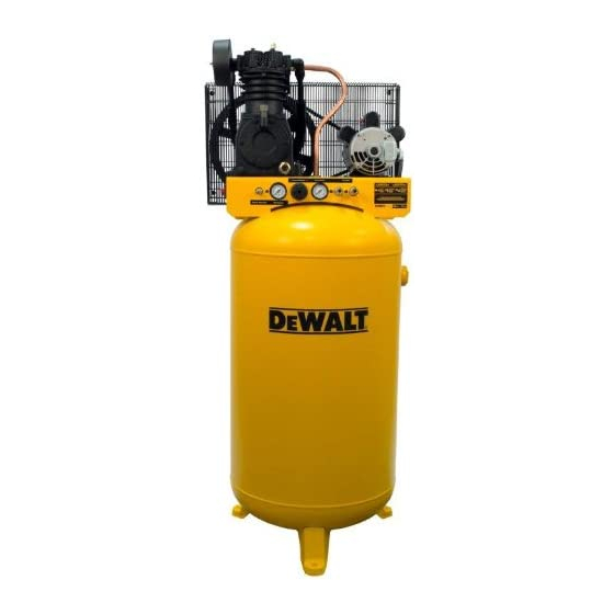
Two Stage, Belt Drive, Electric Air Compressors
Compresseurs d'air électriques à un étage à entraînement par courroie
Compresores eléctricos de aire, de una sola etapa y accionamiento por correa
If you have questions or comments, contact us.
Pour toute question ou tout commentaire, nous contacter.
Si tiene dudas o comentarios, contáctenos.
1-888-895-4549 • www.dewalt.com
INSTRUCTIVO DE OPERACIÓN, CENTROS DE SERVICIO Y
PÓLIZA DE GARANTÍA. ADVERNTENCIA: LÉASE ESTE
INSTRUCTIVO ANTES DE USAR EL PRODUCTO.
Advertisement
Table of Contents

Related Manuals for DeWalt DXCMV5248069


Summary of Contents for DeWalt DXCMV5248069
- Page 1 If you have questions or comments, contact us. Pour toute question ou tout commentaire, nous contacter. Si tiene dudas o comentarios, contáctenos. 1-888-895-4549 • www.dewalt.com INSTRUCTION MANUAL INSTRUCTIVO DE OPERACIÓN, CENTROS DE SERVICIO Y GUIDE D'UTILISATION PÓLIZA DE GARANTÍA. ADVERNTENCIA: LÉASE ESTE INSTRUCTIVO ANTES DE USAR EL PRODUCTO.
-
Page 2: Air Compressor
2 Cylinder Two Stage Oil Lubricated Cast iron crankcase, cylinder, and head Weight: 150 lbs. (68 kg.) Oil Capacity: 18.5 oz. (547 mL) Specifications MODEL DXCMV5248069 WEIGHT 471 lbs. (214 kg) HEIGHT 76.13” WIDTH 31.625” AIR TANK CAPACITY 80 gallons (302,8 liters) APPROX. -
Page 3: Hot Surfaces
Hot Surfaces Definitions: Safety Guidelines COMPRESSOR CYLINDER The definitions below describe the level of severity & HEAD FIG. 2 for each signal word. Please read the manual and pay atten- OUTLET TUBES tion to these symbols. PUMP DANGER: Indicates an imminently hazardous situation CRANKCASE which, if not avoided, will result in death or serious injury. - Page 4 SAVE THESE INSTRUCTIONS • Unattended operation of this • Always remain in attendance product could result in per- with the product when it is sonal injury or property dam- operating. age. To reduce the risk of • Always turn off and discon- fire, do no allow the com- nect electrical supply from DANGER: RISK OF EXPLOSION OR FIRE pressor to operator unat-...
- Page 5 • Unauthorized modifications to • The air tank is designed the safety valve, or any other to withstand specific components which control air operating pressures. Never tank pressure. make adjustments or parts DANGER: RISK OF BURSTING substitutions to alter the factory Air Tank: On February 26, 2002, the U.S. Consumer Product Safety set operating pressures.
- Page 6 DANGER: RISK OF INJURY OR PROP ER TY DAMAGE WHEN WARNING: RISK FROM FLYING OBJECTS TRANSPORTING OR STORING WHAT CAN HAPPEN HOW TO PREVENT IT WHAT CAN HAPPEN HOW TO PREVENT IT • The compressed air stream • Always wear certified safety • Oil can leak or spill and could • Always place compressor can cause soft tissue damage equipment: ANSI Z87.1 eye...
- Page 7 • Repairs attempted by • Any electrical wiring or unqualified personnel can repairs required on this result in serious injury or product should be per- death by electrocution. formed by authorized ser- WARNING: RISK OF HOT SURFACES vice center personnel in WHAT CAN HAPPEN HOW TO PREVENT IT accordance with national • Touching exposed metal such • Never touch any exposed...
- Page 8 WARNING: RISK FROM MOVING PARTS WARNING: RISK OF UNSAFE OPERATION WHAT CAN HAPPEN HOW TO PREVENT IT WHAT CAN HAPPEN HOW TO PREVENT IT • Moving parts such as the • Never operate the compressor pulley, flywheel, and belt can with guards or covers which are • Unsafe op e r a t ion of your air • Review and understand all compressor could lead to se ri- instructions and warnings in...
-
Page 9: Know Your Air Compressor
Know Your Air Compressor READ THIS OWNER’S MANUAL AND SAFETY RULES BEFORE OPERATING YOUR UNIT. Compare the illustrations with your WARNING: RISK OF INJURY FROM LIFTING unit to familiarize yourself with the location of various controls and adjustments. Save this manual for future reference. WHAT CAN HAPPEN HOW TO PREVENT IT FEATURES... - Page 10 reaches cut-out pressure, the check valve closes, allowing air To Adjust Regulator: pressure to remain inside the air tank. 1. Pull regulator knob (E) out. 2. Turn knob clockwise to increase regulated pressure and AIR INTAKE FILTER counter-clockwise to decrease regulated pressure. The filter (A) is designed to clean air entering the 3.
-
Page 11: Installation
Set the Auto/Off switch to OFF (O). DISCONNECTING HOSES Allow the motor to cool. WARNING: Risk of unsafe operation. Firmly grasp hose in hand Depress the red reset button (M on the motor. when installing or disconnecting to prevent hose whip. Set the Auto/Off switch to AUTO (-). -
Page 12: Wiring Instructions
• The air filter must be kept clear of obstructions which could Mark the surface 3/8" Lag reduce air flow to the air compressor. using the holes in Vibration Screw the air compressor (not supplied) HUMID AREAS (not feet as a template. In frequently humid areas, moisture may form in the pump and supplied) Drill holes in the produce sludge in the oil, causing running parts to wear out... -
Page 13: Grounding Instructions
Refer to the Specifications, in the parts manual, for this If any of the above conditions cannot be met, or if operation of the information. compressor repeatedly causes interruption of the power, it may be necessary to operate it from a 20 amp circuit. It is not necessary to The supply line should have the same electrical characteristics change the cord set. - Page 14 • Use pipe that is the same size as the air tank outlet. Piping that is too small will restrict the flow of air. FEEDER LINES SLOPE AIR FLOW AIR FLOW WITH AIR FLOW • If piping is over 100’ (30.5 m) long, use the next larger size. • Bury underground lines below the frost line and avoid pockets where condensation can gather and freeze. Apply pressure MAIN DISTRIBUTION AIR LINES before underground lines are covered to make sure all pipe Slope pipe in direction of air flow.
- Page 15 manual for safety, operation and maintenance instructions. After 30 minutes, turn the Auto/Off switch to the “Off” position. 10. Close the drain valve. Break-in Procedure 11. Turn the Auto/Off switch to the “Auto” position. The air receiver NOTICE: Risk of property damage. Serious damage may result if will fill to “cut-out”...
- Page 16 tered air at an item that could be damaged by moisture. Some air the air tank causing a risk of air tank rupture. tools and accessories may require filtered air. Read the in struc tions 5. Allow the compressor to cool down. for the air tools and accessories.
- Page 17 MAINTENANCE cally when power is on. When performing maintenance, you may be exposed to voltage sources, compressed air, or moving parts. Maintenance Chart Personal injuries can occur. Before performing any maintenance or repair, disconnect power source from the compressor and bleed off Procedure all air pressure.
- Page 18 Checking Air Filter (Fig. 1) condensate contains lubricating oil and/or substances which may be regulated and must be disposed of in accordance with local, state, WARNING: Hot surfaces. Risk of burn. Tubes, pump head, and and federal laws and regulations. surrounding parts are very hot, do not touch (see the Hot Surfaces Set the Auto/Off switch to “Off”.
-
Page 19: Belt Replacement
Checking T = Full The oil level should be to the middle of the sight glass (S). U = Add If needed remove oil fill plug (Q) and slowly add oil until it R = Oil drain plug reaches the middle of the sight glass. S = Oil level sight glass Q = Oil fill plug Changing... -
Page 20: Adjusting Belt Tension
to within 1/16” (1.6 mm) to prevent excessive belt wear. Verify the Loosen motor alignment by performing the following Motor Pulley/Flywheel - mounting screws and Alignment. slide the motor toward Motor Pulley/Flywheel Alignment the air compressor. Remove the belt and NOTE: Once the motor pulley has been moved from its factory set replace with a new one. -
Page 21: Air Compressor Pump Intake And Exhaust Valves
of the motor drive pulley and equalize B1 and B2, using care to voltage sources, compressed air, or moving parts. Before not to disturb the belt alignment performed in step 2. servicing unit unplug or disconnect electrical supply to the air Retighten the motor drive pulley setscrew. -
Page 22: Additional Service
This warranty 1-888-895-4549 or visit our website www.dewalt.com. also does not apply to merchandise sold by DEWALT which has WARNING: The use of any other accessory not recommended been manufactured by and identified as the product of another for use with this tool could be hazardous. - Page 23 and workmanship during the first year of ownership, with the • Labor, service calls, and travel charges, are not covered exceptions noted below. Parts used in repair of whole goods or after the first year of ownership on stationary accessories are warranted for the balance of the original warranty compressors (compressors without handles, or wheels).
- Page 24 FREE WARNING LABEL REPLACEMENT: If your warning labels • All other parts 30 days become illegible or are missing, call 1-888-895-4549 for a free • No return authorization will be issued for electrical replacement. components once items are installed. How do You Get Service? In order to be eligible for service under this warranty you must be the original retail purchaser, and provide proof of purchase from one of the Company’s dealers, distributors, or retail outlet stores.
-
Page 25: Troubleshooting Guide
Troubleshooting Guide This section provides a list of the more frequently encountered malfunctions, their causes and corrective actions. The operator or maintenance personnel can perform some corrective actions, and others may require the assistance of a qualified D WALT technician or your dealer. -
Page 26: Troubleshooting Codes
Troubleshooting Codes CODE POSSIBLE CAUSE POSSIBLE SOLUTION Fittings are not tight Tighten fittings where air can be heard escaping. Check fittings with soapy water solution. DO NOT OVERTIGHTEN. Defective air tank Air tank must be replaced. Do not repair the leak. WARNING: Risk of bursting. - Page 27 CODE POSSIBLE CAUSE POSSIBLE SOLUTION Carbon build-up in pump Contact a D WALT factory service center or a D WALT authorized service center. Belt to tight Check belt tension, see Adjusting Belt Tension under Maintenance. Pulley misalignment See Motor Pulley/Flywheel Alignment under Maintenance. Pump oil is low Add synthetic blend, non-detergent air compressor oil to pump.
- Page 28 CODE POSSIBLE CAUSE POSSIBLE SOLUTION Damaged regulator Replace Regulator open Roate the regulator knob counter-clockwise to its built-in stop and push knob in to lock in place. Low voltage/motor overload Check that power supply is adequate and that compressor is on a dedicated circuit.
- Page 29 GLOSSARY NOTES CFM: Cubic feet per minute. SCFM: Standard cubic feet per minute; a unit of measure of air delivery. PSI: Pounds per square inch; a unit of measure of pressure. Cut-in pressure: Factory set low pressure point that starts the compressor to repressurize the tank to a higher pressure.