Advertisement
Quick Links
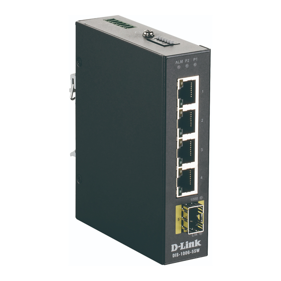
DIS-100G Series Unmanaged
Industrial Gigabit Ethernet
Switch
Quick Installation Guide
Overview
The DIS-100G unmanaged Industrial Gigabit Ethernet
Switch solutions are designed for supporting standard
industrial applications without complex setup to make the
network truly plug-and-play.
If the equipment is used in a manner not specified by the
manufacturer, the protection provided by the equipment
may be impaired.
Package Checklist
Please verify that the box contains the following items:
Item
Unmanaged switch
Wall-mount plates
DIN-Rail kit
M4 Screws
(for the wall mount plates & DIN Rail kit)
DC power terminal block
Quick Installation Guide
Safety Instructions
When a connector is removed during installation, testing, or
servicing, or when an energized fiber is broken, a risk of
ocular exposure to optical energy that may be potentially
hazardous occurs, depending on the laser output power.
The primary hazards of exposure to laser radiation from an
optical-fiber communication system are:
Damage to the eye by accidental exposure to a beam
emitted by a laser source.
Damage to the eye from viewing a connector attached
to a broken fiber or an energized fiber.
Documentation Conventions
The following conventions are used in this quick installation
guide to emphasize information that will be of interest to the
reader.
Danger — The described activity or situation might or
will cause personal injury.
Warning — The described activity or situation might or
will cause equipment damage.
Caution — The described activity or situation might or
will cause service interruption.
Quantity
Note — The information supplements the text or
highlights important points.
1
2
1
4
1
1
DIN-Rail Mounting
Mounting step:
1.
Screw the DIN-Rail bracket on with the bracket and
screws in the accessory kit.
2.
Hook the unit over the DIN rail.
3.
Push the bottom of the unit towards the DIN Rail until it
snaps into place.
2
3
Wall Mounting
(unit: mm)
Mounting step:
1.
Screw on the wall-mount plate on with the plate and
M4 screws in the accessory kit.
1
Advertisement

Related Manuals for D-Link DIS-100G-8W


Summary of Contents for D-Link DIS-100G-8W
- Page 1 Safety Instructions DIN-Rail Mounting When a connector is removed during installation, testing, or Mounting step: servicing, or when an energized fiber is broken, a risk of Screw the DIN-Rail bracket on with the bracket and ocular exposure to optical energy that may be potentially screws in the accessory kit.
- Page 2 (Unshielded Twisted Pair) or STP (Shielded Twisted Pair) Ethernet cables. The pin assignment of RJ-45 connector is shown in the following figure and table. Pin Assignment Assignment T/Rx+,T/Rx- Positive V Port DIS-100G-8W T/Rx+,T/Rx- Negative V DIS-100G-8SW Port T/Rx+,T/Rx- T/Rx+,T/Rx- DIS-100G-8W DIS-100G-8SW...
- Page 3 A 1000Mbps connection is DIP Switch Setting 48-58VDC for PoE compliant. detected Copper 1 to N port Speed No link, a 10Mbps or 100 DIS-100G-5W DIS-100G-8W Mbps connection is detected Status DIS-100G-5PSW DIS-100G-5SW DIS-100G-8SW SFP 1 to N port On Green...
- Page 4 This equipment generates, uses, your appropriate local D-Link support website. and can radiate radio frequency energy and, if not installed and 警告使用者: used in accordance with the instruction manual, may cause Warranty Information 此為甲類的資訊技術設備,在居住環境中使用時,可能會...