Table of Contents
Advertisement
Quick Links
Advertisement
Table of Contents

Related Manuals for Huawei RRU3942


Summary of Contents for Huawei RRU3942
- Page 1 RRU3942 Installation Guide Issue Date HUAWEI TECHNOLOGIES CO., LTD.
- Page 2 All other trademarks and trade names mentioned in this document are the property of their respective holders. Notice The purchased products, services and features are stipulated by the contract made between Huawei and the customer. All or part of the products, services and features described in this document may not be within the purchase scope or the usage scope.
-
Page 3: About This Document
Installation Guide About This Document About This Document Purpose This document describes the process of installing a DC RRU3942 (referred to as RRU in this document). Product Version The following table lists the product version related to this document. Product Name... - Page 4 Provides additional information to emphasize or supplement important points of the main text. General Conventions The general conventions that may be found in this document are defined as follows. Issue () Huawei Proprietary and Confidential Copyright © Huawei Technologies Co., Ltd.
- Page 5 Multi-level menus are in boldface and separated by the ">" signs. For example, choose File > Create > Folder. Keyboard Operations The keyboard operations that may be found in this document are defined as follows. Issue () Huawei Proprietary and Confidential Copyright © Huawei Technologies Co., Ltd.
- Page 6 Press the primary mouse button twice continuously and quickly without moving the pointer. Drag Press and hold the primary mouse button and move the pointer to a certain position. Issue () Huawei Proprietary and Confidential Copyright © Huawei Technologies Co., Ltd.
-
Page 7: Table Of Contents
RRU3942 Installation Guide Contents Contents About This Document........................ii 1 Changes in the RRU3942 Installation Guide................1 2 Installation Preparations......................2 2.1 Reference Documents............................3 2.2 Tools and Instruments............................3 2.3 Skills and Requirements for Onsite Personnel....................4 3 Information About the Installation...................5 3.1 RRU Exterior..............................6 3.2 RRU Ports................................6... - Page 8 8 Checking the RRU Hardware Installation................84 9 Powering On an RRU.........................85 10 Appendix.............................86 10.1 Adding an Easy Power Receptacle (Pressfit Type) Connector to the RRU Power Cable on the RRU Side ....................................87 Issue () Huawei Proprietary and Confidential Copyright © Huawei Technologies Co., Ltd.
-
Page 9: Changes In The Rru3942 Installation Guide
Installation Guide 1 Changes in the RRU3942 Installation Guide Changes in the RRU3942 Installation Guide This chapter describes the changes in the RRU3942 Installation Guide. 02() This is the second official release. Compared with issue 01 (2011-09-30), this issue includes the following new information:... -
Page 10: Installation Preparations
2.3 Skills and Requirements for Onsite Personnel Onsite personnel must be qualified and trained. Before performing any operation, onsite personnel must be familiar with correct operation methods and safety precautions. Issue () Huawei Proprietary and Confidential Copyright © Huawei Technologies Co., Ltd. -
Page 11: Reference Documents
Heat gun Phillips screwdriver (M3 to Flat-head screwdriver (M3 to Rubber mallet COAX crimping tool Wire stripper Utility knife Cable cutter Adjustable wrench (capacity ≥ 32 mm [1.26 in.]) Issue () Huawei Proprietary and Confidential Copyright © Huawei Technologies Co., Ltd. -
Page 12: Skills And Requirements For Onsite Personnel
Before the installation, pay attention to the following items: The customer's technical engineers must be trained by Huawei and be familiar with the proper installation and operation methods. The number of onsite personnel depends on the engineering schedule and installation environment. -
Page 13: Information About The Installation
3.5 Installation Clearance Requirements of an RRU This section describes the requirements for the installation clearance of a single RRU and multiple RRUs and the requirements for the installation spacing between RRUs. Issue () Huawei Proprietary and Confidential Copyright © Huawei Technologies Co., Ltd. -
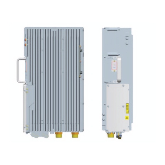
Page 14: Rru Exterior
This section describes RRU ports positioned on the RRU panels. An RRU has a bottom panel, cabling cavity panel, and indicator panel. Figure 3-3 shows RRU ports on the panels. Issue () Huawei Proprietary and Confidential Copyright © Huawei Technologies Co., Ltd. - Page 15 Table 3-1 RRU ports and indicators on the panels Item Label Description (1) Ports at the bottom ANT_TX/RXA TX/RX port A, supporting RET signal transmission ANT_RXC RX port C ANT_RXD Port RX port D Issue () Huawei Proprietary and Confidential Copyright © Huawei Technologies Co., Ltd.
- Page 16 RF Ports MBTS V100R004 2T2R ANT_TX/RXA is used with ANT_TX/ RXB. Versions later than One 1T2R ANT_TX/RXA is MBTS V100R004 used with ANT_RXC. ANT_TX/RXB is used with ANT_RXD. Issue () Huawei Proprietary and Confidential Copyright © Huawei Technologies Co., Ltd.
-
Page 17: Rru Indicators
No alarm is generated. Green The module is working properly with TX channels enabled. Blinking (on for The module is working properly with TX 1s and off for 1s) channels disabled. Issue () Huawei Proprietary and Confidential Copyright © Huawei Technologies Co., Ltd. -
Page 18: Installation Options
This section describes RRU installation options. An RRU can be installed on a pole, U-steel, angle steel, or wall. Installing an RRU on a Pole Figure 3-4 shows the diameter of pole for installing an AAU3801. Issue () Huawei Proprietary and Confidential Copyright © Huawei Technologies Co., Ltd. - Page 19 RRUs can be installed on the pole and the side-mounted installation is not recommended. Figure 3-5 shows an RRU installed on a pole. Figure 3-5 RRU installed on a pole Installing an RRU on U-steel Figure 3-6 shows U-steel specifications. Issue () Huawei Proprietary and Confidential Copyright © Huawei Technologies Co., Ltd.
- Page 20 Figure 3-7 Requirements for the vertical deviation angle of U-steel or angle steel (1) RRU (2) U-steel or angle steel Figure 3-8 shows an RRU installed on U-steel. Issue () Huawei Proprietary and Confidential Copyright © Huawei Technologies Co., Ltd.
- Page 21 The vertical deviation angle of angle steel must be less than or equal to 10 degrees, as shown Figure 3-7. Figure 3-10 shows an RRU installed on angle steel. Issue () Huawei Proprietary and Confidential Copyright © Huawei Technologies Co., Ltd.
- Page 22 The brackets cannot be combined when RRUs are installed on a wall, as shown in Figure 3-11. Figure 3-11 Correct placement of brackets Figure 3-12 shows an RRU installed on a wall. Issue () Huawei Proprietary and Confidential Copyright © Huawei Technologies Co., Ltd.
-
Page 23: Installation Clearance Requirements Of An Rru
This section describes the recommended and minimum installation clearance for a single RRU. Recommended Installation Clearance for a Single RRU Figure 3-13 shows the recommended installation clearance for a single RRU. Issue () Huawei Proprietary and Confidential Copyright © Huawei Technologies Co., Ltd. - Page 24 Figure 3-14 Minimum installation clearance for a single RRU Minimum Installation Clearance for a Single RRU Installed on a Tower Figure 3-15 shows the minimum installation clearance for a single RRU installed on a tower. Issue () Huawei Proprietary and Confidential Copyright © Huawei Technologies Co., Ltd.
-
Page 25: Installation Clearance For Multiple Rrus
This section describes the recommended and minimum installation clearance for multiple RRUs. Recommended Installation Clearance for Multiple RRUs Installed in Centralized Mode Figure 3-16 shows the recommended installation clearance for multiple RRUs installed in centralized mode. Issue () Huawei Proprietary and Confidential Copyright © Huawei Technologies Co., Ltd. - Page 26 Minimum Installation Clearance for Multiple RRUs Installed in Centralized Mode Figure 3-17 shows the minimum installation clearance for multiple RRUs installed in centralized mode. Figure 3-17 Minimum installation clearance for multiple RRUs installed in centralized mode Issue () Huawei Proprietary and Confidential Copyright © Huawei Technologies Co., Ltd.
- Page 27 Minimum Clearance for Multiple RRUs Installed on a Wall in Standard Mode Figure 3-19 shows the minimum clearance for multiple RRUs installed on a wall in standard mode. Issue () Huawei Proprietary and Confidential Copyright © Huawei Technologies Co., Ltd.
-
Page 28: Installation Spacing Between Rrus
RRUs side-mounted on a wall. Figure 3-20 Recommended clearance for multiple RRUs side-mounted on a wall 3.5.3 Installation Spacing Between RRUs This section describes the horizontal and vertical installation spacing between RRUs. Issue () Huawei Proprietary and Confidential Copyright © Huawei Technologies Co., Ltd. - Page 29 RRUs. Figure 3-22 Minimum horizontal spacing between RRUs Recommended Vertical Spacing Between RRUs Figure 3-23 shows the recommended vertical spacing between RRUs. Issue () Huawei Proprietary and Confidential Copyright © Huawei Technologies Co., Ltd.
- Page 30 Installation Guide 3 Information About the Installation Figure 3-23 Recommended vertical spacing between RRUs Minimum Vertical Spacing Between RRUs Figure 3-24 shows the minimum vertical spacing between RRUs. Issue () Huawei Proprietary and Confidential Copyright © Huawei Technologies Co., Ltd.
- Page 31 RRU3942 Installation Guide 3 Information About the Installation Figure 3-24 Minimum vertical spacing between RRUs Issue () Huawei Proprietary and Confidential Copyright © Huawei Technologies Co., Ltd.
-
Page 32: Unpacking The Equipment
The total number does not tally with the Find out the cause and report any missing packing list articles to the local Huawei office. Step 2 Check the exterior of the packing case. Issue () Huawei Proprietary and Confidential... - Page 33 ----End Issue () Huawei Proprietary and Confidential Copyright © Huawei Technologies Co., Ltd.
-
Page 34: Installation Process
The installation process involves installing an RRU and RRU cables, checking the RRU hardware installation, and powering on the RRU. Figure 5-1 shows the process of installing an RRU. Figure 5-1 Process of installing an RRU Issue () Huawei Proprietary and Confidential Copyright © Huawei Technologies Co., Ltd. -
Page 35: Installing The Rru
This section describes the procedure for installing the RRU on a wall and the precautions that must be taken during the installation. 6.6 Hoisting an RRU onto a Tower Issue () Huawei Proprietary and Confidential Copyright © Huawei Technologies Co., Ltd. - Page 36 The RRU can be installed on a pole, U-steel, or angle steel. This section describes the procedure for hoisting the RRU and mounting kits onto the tower and the precautions that must be taken. Issue () Huawei Proprietary and Confidential Copyright © Huawei Technologies Co., Ltd.
-
Page 37: Mounting Kits For An Rru
(2) Dual-nut bolt assembly (3) Main mounting bracket (4) Hoist clamp on the bracket main mounting bracket 6.2 Installing the RRU on a Pole One or more RRUs can be installed on a pole. Issue () Huawei Proprietary and Confidential Copyright © Huawei Technologies Co., Ltd. - Page 38 RRUs installed on a pole. Figure 6-4 Two RRUs installed on a pole Figure 6-5, Figure 6-6, and Figure 6-7 show more than two RRUs installed on a pole. Issue () Huawei Proprietary and Confidential Copyright © Huawei Technologies Co., Ltd.
- Page 39 Installation Guide 6 Installing the RRU Figure 6-5 Three RRUs installed on a pole in centralized mode Figure 6-6 Four RRUs installed on a pole in centralized mode Issue () Huawei Proprietary and Confidential Copyright © Huawei Technologies Co., Ltd.
-
Page 40: Installing A Single Rru
If the RRU must be installed on a tower, see 3.5.1 Installation Clearance for a Single to determine a position. If the RRU must be installed on the ground, see Figure 6-8 to determine a position. Issue () Huawei Proprietary and Confidential Copyright © Huawei Technologies Co., Ltd. - Page 41 Tighten the two dual-nut bolt assemblies alternatively. After the main and auxiliary brackets are secured properly, measure the spacing between the brackets on both sides and ensure that the spacing is the same on the two sides. Issue () Huawei Proprietary and Confidential Copyright © Huawei Technologies Co., Ltd.
-
Page 42: Installing Two Rrus
Figure 6-11 Installing the RRU on the main mounting bracket ----End 6.2.2 Installing Two RRUs This section describes the procedure for installing two RRUs on a pole and the precautions that must be taken during the installation. Issue () Huawei Proprietary and Confidential Copyright © Huawei Technologies Co., Ltd. - Page 43 Step 3 Interchange the cover plate and plastic screws in the front and the attachment plate and stainless steel screws at the rear of the second RRU, as shown in Figure 6-14. Issue () Huawei Proprietary and Confidential Copyright © Huawei Technologies Co., Ltd.
- Page 44 Step 4 Install the second RRU on the main mounting bracket, as shown in Figure 6-15. Figure 6-15 Installing the second RRU on the main mounting bracket ----End Issue () Huawei Proprietary and Confidential Copyright © Huawei Technologies Co., Ltd.
-
Page 45: Installing Multiple Rrus
Install the attachment plate onto the RRU side, and tighten the stainless steel screws on the attachment plate to 5 N·m (44.25 lbf·in.) using a torque screwdriver. Step 3 Install the first RRU on the main mounting bracket, as shown in Figure 6-17. Issue () Huawei Proprietary and Confidential Copyright © Huawei Technologies Co., Ltd. - Page 46 Figure 6-18. Figure 6-18 Installing the second main mounting bracket Step 5 Install the second RRU on the second main mounting bracket, as shown in Figure 6-19. Issue () Huawei Proprietary and Confidential Copyright © Huawei Technologies Co., Ltd.
- Page 47 Figure 6-20. Figure 6-20 Installing the third RRU on the third main mounting bracket Step 7 Install the fourth main mounting bracket, as shown in Figure 6-21. Issue () Huawei Proprietary and Confidential Copyright © Huawei Technologies Co., Ltd.
-
Page 48: Installing The Rru On U-Steel
Before you install an RRU on a tower, the RRU and mounting kits are hoisted onto the tower. For details, see 6.6 Hoisting an RRU onto a Tower. Issue () Huawei Proprietary and Confidential Copyright © Huawei Technologies Co., Ltd. - Page 49 If the RRU must be installed on the ground, see Figure 6-24 to determine a position. Figure 6-24 Distance between the main mounting bracket and the ground Issue () Huawei Proprietary and Confidential Copyright © Huawei Technologies Co., Ltd.
- Page 50 Tighten the two dual-nut bolt assemblies alternatively. After the main and auxiliary brackets are secured properly, measure the spacing between the brackets on both sides and ensure that the spacing is the same on the two sides. Issue () Huawei Proprietary and Confidential Copyright © Huawei Technologies Co., Ltd.
- Page 51 Step 5 Install the RRU on the main mounting bracket until the RRU snaps shut, as shown in Figure 6-27. Figure 6-27 Installing the RRU on the main mounting bracket Issue () Huawei Proprietary and Confidential Copyright © Huawei Technologies Co., Ltd.
-
Page 52: Installing The Rru On Angle Steel
6.6 Hoisting an RRU onto a Tower. The hoist clamp on the main mounting bracket is secured properly. Context Figure 6-29 shows the top view of the RRU installed on angle steel. Issue () Huawei Proprietary and Confidential Copyright © Huawei Technologies Co., Ltd. - Page 53 Step 3 Install the bracket assembly on angle steel, and then fit the other end of the auxiliary mounting bracket to the other dual-nut bolt assembly, as shown in Figure 6-31. Issue () Huawei Proprietary and Confidential Copyright © Huawei Technologies Co., Ltd.
- Page 54 Figure 6-32 Securing the bracket assembly onto angle steel Issue () Huawei Proprietary and Confidential Copyright © Huawei Technologies Co., Ltd.
-
Page 55: Installing The Rru On A Wall
Step 1 Place the auxiliary mounting bracket against the installation position, use a level to verify that the auxiliary mounting bracket is placed horizontally, and then mark anchor points with a marker, as shown in Figure 6-34. Issue () Huawei Proprietary and Confidential Copyright © Huawei Technologies Co., Ltd. - Page 56 (2) Spring washer 10 (3) Plastic tube (4) Flat washer 10 (5) Expansion tube Step 2 Drill holes at the anchor points, and then insert expansion bolt assemblies, as shown in Figure 6-36. Issue () Huawei Proprietary and Confidential Copyright © Huawei Technologies Co., Ltd.
- Page 57 Step 3 Fit the auxiliary mounting bracket on the expansion bolt, and then use a torque wrench (17 mm [0.67 in.]) to tighten the expansion bolt to 30 N·m (265.52 lbf·in.), as shown in Figure 6-37. Issue () Huawei Proprietary and Confidential Copyright © Huawei Technologies Co., Ltd.
- Page 58 Step 4 Loosen the screws on the main mounting bracket and store them properly. Step 5 Install the main mounting bracket, as shown in Figure 6-38. Figure 6-38 Installing the main mounting bracket Issue () Huawei Proprietary and Confidential Copyright © Huawei Technologies Co., Ltd.
-
Page 59: Hoisting An Rru Onto A Tower
RRUs can be installed on a pole in back-to-back mode. RRUs cannot be installed on the side, and the brackets for more than two RRUs cannot be combined. Issue () Huawei Proprietary and Confidential Copyright © Huawei Technologies Co., Ltd. - Page 60 RRU handle and use the sling as a traction sling, as shown in Figure 6-41. Figure 6-41 Binding the RRU (1) Lifting sling (2) Lifting eye (3) Traction sling (4) Handle Issue () Huawei Proprietary and Confidential Copyright © Huawei Technologies Co., Ltd.
- Page 61 Do not hoist the RRU by the handle or lifting eye only, as shown in Figure 6-42 Figure 6-43. Figure 6-42 Incorrect binding method Figure 6-43 Incorrect binding method Issue () Huawei Proprietary and Confidential Copyright © Huawei Technologies Co., Ltd.
- Page 62 Installation engineer A catches the RRU, install the RRU on the main mounting bracket until the RRU snaps shut, and then unties the sling. NOTE The procedure for hoisting the RRU onto the tower is for your reference only. ----End Issue () Huawei Proprietary and Confidential Copyright © Huawei Technologies Co., Ltd.
-
Page 63: Installing Rru Cables
This section describes the procedure for installing a CPRI fiber optic cable. 7.12 Installing an RRU Alarm Cable This section describes the procedure for installing an RRU alarm cable. Issue () Huawei Proprietary and Confidential Copyright © Huawei Technologies Co., Ltd. - Page 64 7 Installing RRU Cables 7.13 Closing the Cover Plate of an RRU Cabling Cavity This section describes the procedure for closing the cover plate of an RRU cabling cavity. Issue () Huawei Proprietary and Confidential Copyright © Huawei Technologies Co., Ltd.
-
Page 65: Cabling Requirements
Indoor Cabling Requirements Cables are routed indoors through the feeder window. Drip loops must be made outside the feeder window, and the requirements for the minimum bending radius are met. Issue () Huawei Proprietary and Confidential Copyright © Huawei Technologies Co., Ltd. - Page 66 Cable clips must be vertical with cables, and the cables in a cable clip must be parallel. After routing cables neatly and correctly, tighten the screws on cable clips. Secure cables on the cable tray, as shown in Figure 7-1. Issue () Huawei Proprietary and Confidential Copyright © Huawei Technologies Co., Ltd.
- Page 67 RRU3942 Installation Guide 7 Installing RRU Cables Figure 7-1 Securing cables on the cable tray Secure cables on the tower, as shown in Figure 7-2. Issue () Huawei Proprietary and Confidential Copyright © Huawei Technologies Co., Ltd.
- Page 68 If the length of power cables is insufficient, replace the cables rather than adding connectors or soldering joints to lengthen the cables. Cables must be routed by only qualified and trained personnel before all preparations are made. Issue () Huawei Proprietary and Confidential Copyright © Huawei Technologies Co., Ltd.
- Page 69 If fiber optic cables need to be routed close to a device on the tower, secure the cables to the guardrail or pole with cable clips. The device cannot be far away from the position for securing the cables. Issue () Huawei Proprietary and Confidential Copyright © Huawei Technologies Co., Ltd.
-
Page 70: Cable Connections
(4) RRU AISG extension cable (5) RRU power cable (6) CPRI fiber optic cable (7) RRU alarm cable Figure 7-4 shows the cable connections for a single RRU in the multi-mode scenario. Issue () Huawei Proprietary and Confidential Copyright © Huawei Technologies Co., Ltd. - Page 71 (4) RRU AISG extension cable (5) RRU power cable (6) CPRI fiber optic cable (7) RRU alarm cable Figure 7-5 shows the cable connections for multiple RRUs in the single-mode scenario. Issue () Huawei Proprietary and Confidential Copyright © Huawei Technologies Co., Ltd.
- Page 72 (2) RRU RF jumper (3) RRU power cable (4) CPRI fiber optic cable Figure 7-6 shows the CPRI fiber optic cable connections for multiple RRUs in the multi-mode scenario. Issue () Huawei Proprietary and Confidential Copyright © Huawei Technologies Co., Ltd.
-
Page 73: Installation Process
Figure 7-6 CPRI fiber optic cable connections for multiple RRUs in the multi-mode scenario 7.3 Installation Process This section describes the process of installing RRU cables. Figure 7-7 shows the process of installing RRU cables. Issue () Huawei Proprietary and Confidential Copyright © Huawei Technologies Co., Ltd. -
Page 74: Rru Cable List
Position RRU PGND OT terminal (M6, Ground OT terminal Ground terminal Cable terminal on the on the ground bar 16 mm [0.025 in. (M8, 16 mm [0.025 in. Issue () Huawei Proprietary and Confidential Copyright © Huawei Technologies Co., Ltd. - Page 75 GTMU in the CPRI port on the LBBP in the BBU UMTS+LTE (UL) mode CPRI port on the WBBP in the CPRI port on the LBBP in the BBU Issue () Huawei Proprietary and Confidential Copyright © Huawei Technologies Co., Ltd.
-
Page 76: Installing An Rru Pgnd Cable
The cross-sectional area of an RRU PGND cable is 16 mm (0.025 in. ). The OT terminals at two ends of the cable are M6 and M8 terminals respectively. Issue () Huawei Proprietary and Confidential Copyright © Huawei Technologies Co., Ltd. - Page 77 7-8. Figure 7-8 Installing an RRU PGND cable NOTE Crimp OT terminals in correct positions, as shown in Figure 7-9. Figure 7-9 Correct position of an OT terminal Issue () Huawei Proprietary and Confidential Copyright © Huawei Technologies Co., Ltd.
-
Page 78: Installing An Rru Rf Jumper
Step 2 Link the other end of the RF jumper to the external antenna system. Step 3 Waterproof the connectors of the RF jumper by referring to Figure 7-11. Issue () Huawei Proprietary and Confidential Copyright © Huawei Technologies Co., Ltd. - Page 79 Step 4 Check the dustproof caps on antenna connectors. In outdoor scenarios, dustproof caps must be waterproofed, as shown in Figure 7-12. CAUTION Do not remove dustproof caps from vacant antenna connectors. Issue () Huawei Proprietary and Confidential Copyright © Huawei Technologies Co., Ltd.
-
Page 80: Installing An Inter-Rru Rf Cable
Step 1 Link the DB2W2 connector at one end of the RF cable to the RX_IN/OUT port of an RRU, and link the other end to the RX_IN/OUT port of the other RRU, as shown in Figure 7-13. Issue () Huawei Proprietary and Confidential Copyright © Huawei Technologies Co., Ltd. -
Page 81: Installing An Rru Aisg Multi-Wire Cable And Aisg Extension Cable
Install an AISG multi-wire cable that is not configured with an AISG extension cable. Link the waterproofed DB9 connector at one end the AISG multi-wire cable to the RET port on the RRU bottom, as shown in Figure 7-14. Issue () Huawei Proprietary and Confidential Copyright © Huawei Technologies Co., Ltd. - Page 82 RET port on the RRU bottom, and link the other end to the standard AISG male connector of the AISG extension cable, as shown in Figure 7-15. Figure 7-15 Installing an RRU AISG multi-wire cable Issue () Huawei Proprietary and Confidential Copyright © Huawei Technologies Co., Ltd.
-
Page 83: Opening The Cover Plate Of An Rru Cabling Cavity
Step 2 Loosen the protection screw on the cover plate of the RRU cabling cavity using an M4 Phillips screwdriver, and then lower the handle to open the cover plate, as shown in Figure 7-17. Issue () Huawei Proprietary and Confidential Copyright © Huawei Technologies Co., Ltd. - Page 84 (8) Cabling cavity Step 3 Loosen the screws on the clip, and open the clip, as shown Figure 7-19. NOTE Open the clip only for the associated cable. Issue () Huawei Proprietary and Confidential Copyright © Huawei Technologies Co., Ltd.
-
Page 85: Installing An Rru Power Cable
Link the easy power receptacle (pressfit type) connector at one end of the RRU power cable to the power supply socket on the RRU, as shown in Figure 7-20. Issue () Huawei Proprietary and Confidential Copyright © Huawei Technologies Co., Ltd. - Page 86 RRU, as shown in Figure 7-20. Link the easy power receptacle (pressfit type) connector at one end of the RRU power cable to the RRU0 port on the EPU subrack. Issue () Huawei Proprietary and Confidential Copyright © Huawei Technologies Co., Ltd.
-
Page 87: Installing A Cpri Fiber Optic Cable
Step 1 Lower the pullers of two optical modules, insert one optical module into the CPRI0 port on the RRU and the other optical module into the CPRI port on the BBU, and then raise the pullers, as shown in Figure 7-21. Issue () Huawei Proprietary and Confidential Copyright © Huawei Technologies Co., Ltd. - Page 88 Step 2 Connect the end labeled 1A and 1B of the fiber optic cable to the optical module on the RRU side, as shown in Figure 7-22. Figure 7-22 Installing a CPRI fiber optic cable Issue () Huawei Proprietary and Confidential Copyright © Huawei Technologies Co., Ltd.
-
Page 89: Installing An Rru Alarm Cable
Figure 7-23. Figure 7-23 Installing an RRU alarm cable Issue () Huawei Proprietary and Confidential Copyright © Huawei Technologies Co., Ltd. -
Page 90: Closing The Cover Plate Of An Rru Cabling Cavity
Ensure that the exposed shield layer of the power cable is properly tightened using the clip. Step 2 Insert waterproof blocks into vacant cable troughs in the cabling cavity, as shown in Figure 7-25. Issue () Huawei Proprietary and Confidential Copyright © Huawei Technologies Co., Ltd. - Page 91 Tighten the screws on the cover plate in the sequence shown in the figure. Step 4 Take off the ESD gloves, and pack up all the tools. ----End Issue () Huawei Proprietary and Confidential Copyright © Huawei Technologies Co., Ltd.
-
Page 92: Checking The Rru Hardware Installation
The connectors of each signal cable are intact and securely linked, and these cables are not damaged or broken. Labels are correct, legible, and complete at both ends of each cable, feeder, and jumper. Issue () Huawei Proprietary and Confidential Copyright © Huawei Technologies Co., Ltd. -
Page 93: Powering On An Rru
After you unpack an RRU, you must power on it within 24 hours. If you power off the RRU for maintenance, you must restore power to the RRU within 24 hours. Figure 9-1 shows the RRU power-on check process. Figure 9-1 RRU power-on check process Issue () Huawei Proprietary and Confidential Copyright © Huawei Technologies Co., Ltd. -
Page 94: Appendix
10.1 Adding an Easy Power Receptacle (Pressfit Type) Connector to the RRU Power Cable on the RRU Side This section describes the procedure for adding an easy power receptacle (pressfit type) connector to the RRU power cable on the RRU side. Issue () Huawei Proprietary and Confidential Copyright © Huawei Technologies Co., Ltd. -
Page 95: Adding An Easy Power Receptacle (Pressfit Type) Connector To The Rru Power Cable On The Rru Side
10-2. Figure 10-2 Determining the length of the power cable Step 3 Strip the specified length of the sheath off the power cable, as shown in Figure 10-3. Issue () Huawei Proprietary and Confidential Copyright © Huawei Technologies Co., Ltd. - Page 96 Figure 10-5 Matched length Step 5 Add an easy power receptacle (pressfit type) connector to two core wires. Tighten the screws using a Phillips screwdriver, as shown in Figure 10-6. Issue () Huawei Proprietary and Confidential Copyright © Huawei Technologies Co., Ltd.
- Page 97 Step 6 Strip the specified length of the sheath off the power cable to expose the intact shield layer, as shown in Figure 10-8. Figure 10-8 Stripping the sheath off the power cable Issue () Huawei Proprietary and Confidential Copyright © Huawei Technologies Co., Ltd.
- Page 98 Each core wire is exposed outside the easy power receptacle (pressfit type) connector for 1.5 mm (0.059 [in.]), as shown in Figure 10-9. Figure 10-9 Inserting core wires into the easy power receptacle (pressfit type) connector ----End Issue () Huawei Proprietary and Confidential Copyright © Huawei Technologies Co., Ltd.