Table of Contents
Advertisement
Quick Links
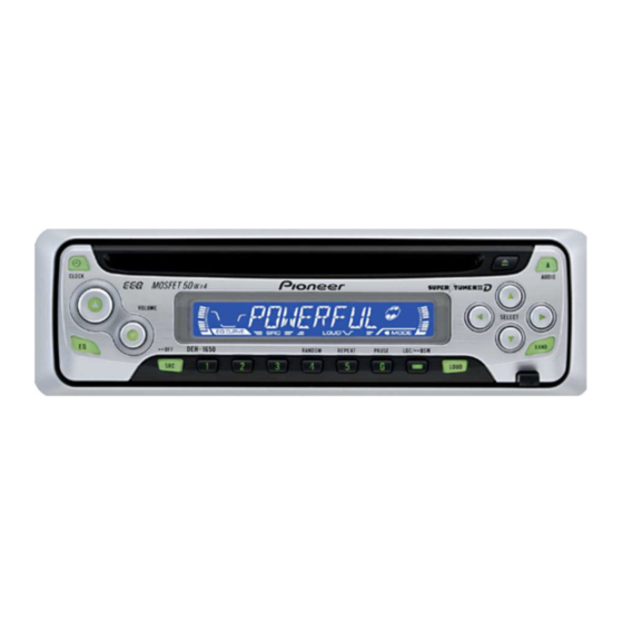
HIGH POWER CD PLAYER WITH FM/AM TUNER
DEH-1650
DEH-1650B
This service manual should be used together with the following manual(s):
Model No.
Order No.
CX-3110
CRT3178
For details, refer to "Important symbols for good services".
PIONEER CORPORATION
PIONEER ELECTRONICS (USA) INC. P.O. Box 1760, Long Beach, CA 90801-1760, U.S.A.
PIONEER EUROPE NV Haven 1087, Keetberglaan 1, 9120 Melsele, Belgium
PIONEER ELECTRONICS ASIACENTRE PTE. LTD. 253 Alexandra Road, #04-01, Singapore 159936
PIONEER CORPORATION 2003
Mech.Module
S10.1
CD Mech. Module : Circuit Description, Mech. Description, Disassembly
4-1, Meguro 1-chome, Meguro-ku, Tokyo 153-8654, Japan
DEH-1650/XU/ES
XU/ES
Remarks
ORDER NO.
CRT3176
XU/ES, XU/CN
K-ZZA. OCT. 2003 printed in Japan
Advertisement
Table of Contents

Related Manuals for Pioneer DEH-1650XU/ES


Summary of Contents for Pioneer DEH-1650XU/ES
- Page 1 PIONEER CORPORATION 4-1, Meguro 1-chome, Meguro-ku, Tokyo 153-8654, Japan PIONEER ELECTRONICS (USA) INC. P.O. Box 1760, Long Beach, CA 90801-1760, U.S.A. PIONEER EUROPE NV Haven 1087, Keetberglaan 1, 9120 Melsele, Belgium PIONEER ELECTRONICS ASIACENTRE PTE. LTD. 253 Alexandra Road, #04-01, Singapore 159936 PIONEER CORPORATION 2003 K-ZZA.
-
Page 2: Safety Information
SAFETY INFORMATION This service manual is intended for qualified service technicians; it is not meant for the casual do-it-yourselfer. Qualified technicians have the necessary test equipment and tools, and have been trained to properly and safely repair complex products such as those covered by this manual. Improperly performed repairs can adversely affect the safety and reliability of the product and may void the warranty. - Page 3 [ Important symbols for good services ] In this manual, the symbols shown-below indicate that adjustments, settings or cleaning should be made securely. When you find the procedures bearing any of the symbols, be sure to fulfill them: 1. Product safety You should conform to the regulations governing the product (safety, radio and noise, and other regulations), and should keep the safety during servicing by following the safety instructions described in this manual.
-
Page 4: Table Of Contents
CONTENTS SAFETY INFORMATION ............................. 2 1. SPECIFICATIONS ............................6 2. EXPLODED VIEWS AND PARTS LIST ......................8 2.1 PACKING ..............................8 2.2 EXTERIOR............................... 10 2.3 CD MECHANISM MODULE........................14 3. BLOCK DIAGRAM AND SCHEMATIC DIAGRAM ..................16 3.1 BLOCK DIAGRAM ........................... 16 3.2 OVERALL CONNECTION DIAGRAM(GUIDE PAGE)................ - Page 5 DEH-1650/XU/ES...
-
Page 6: Specifications
1. SPECIFICATIONS DEH-1650/XU/ES... - Page 7 DEH-1650/XU/ES...
-
Page 8: Exploded Views And Parts List
2. EXPLODED VIEWS AND PARTS LIST OTES : • Parts marked by " * " are generally unavailable because they are not in our Master Spare Parts List. • Screw adjacent to mark on the product are used for disassembly. •... - Page 9 (2) CONTRAST TABLE DEH-1650/XU/ES, DEH-1650B/XU/ES and DEH-1650/XU/CN are constructed the same except for the following: Mark Description DEH-1650/XU/ES DEH-1650B/XU/ES DEH-1650/XU/CN 11-1 Owner's Manual YRD5005 YRD5005 YRB5001 11-2 Installation Manual YRD5010 YRD5010 YRB5004 11-3 Warranty Card Not used Not used ARY7046 Carton YHG5007 YHG5008...
-
Page 10: Exterior
2.2 EXTERIOR DEH-1650/XU/ES... - Page 11 (1) EXTERIOR SECTION PARTS LIST Mark No. Description Part No. Mark No. Description Part No. Connector(CN651) CKS3835 Screw BSZ26P060FTC Antenna Jack(CN401) CKX1056 Screw BSZ30P060FTC Holder CND1328 Screw BSZ30P200FTC Heat Sink CNR1668 Cord Assy CDE7060 Cable CDE7113 FM/AM Tuner Unit CWE1646 Holder CND1054 Case...
- Page 12 (2) CONTRAST TABLE DEH-1650/XU/ES, DEH-1650B/XU/ES and DEH-1650/XU/CN are constructed the same except for the following: Mark Description DEH-1650/XU/ES DEH-1650B/XU/ES DEH-1650/XU/CN Panel YNS5022 YNS5022 YNS5029 Tuner Amp Unit YWM5011 YWM5017 YWM5021 Detach Grille Assy YXA5020 YXA5022 YXA5024 Button(VOLUME+) YAC5006 YAC5006 YAC5005 Button(VOLUME-) YAC5009 YAC5009...
- Page 13 DEH-1650/XU/ES...
-
Page 14: Cd Mechanism Module
2.3 CD MECHANISM MODULE 1GEM1024 2GEM1045 3GEM1035 DEH-1650/XU/ES... - Page 15 CD MECHANISM MODULE SECTION PARTS LIST Mark No. Description Part No. Mark No. Description Part No. CD Core Unit(S10.1) CWX2947 Gear CNV7208 Connector(CN101) CKS4182 Gear CNV7209 Connector(CN701) CKS4188 Gear CNV7210 Screw BMZ20P035FTC Gear CNV7211 Screw BSZ20P040FTC Gear CNV7212 Screw(M2x4) CBA1362 Rack CNV7214 Screw(M2x3)
-
Page 16: Block Diagram And Schematic Diagram
3. BLOCK DIAGRAM AND SCHEMATIC DIAGRAM 3.1 BLOCK DIAGRAM TUNER AMP UNIT 10 9 8 18 19 20 21 FM/AM TUNER UNIT IC 5 IC 3 EEPROM 3.3V 5.0V ANTENNA CN401 AM ANT FMRF IC 2 2.5V IC 1 FM ANT 3.3V FMRF MIXER, IF AMP... - Page 17 RESET IC 961 S-80834CNY PRE OUT CN352 Q352 TUNPCE2 TUNPCE1 TUNPDI TUNPDO TUNPCK VDD REGULATOR Q911 Q912 SYSTEM CONTROLLER IC 601(1/2) PE5330C DALMON CN901 BACKUP SENSE B.UP FUSE BSENS BACK UP Q931 ASENS ACC SENSE B.UP ELECTRONIC VOLUME/ SOURCE SELECTOR POWER AMP 6,20 TUN L...
-
Page 18: Overall Connection Diagram(Guide Page)
3.2 OVERALL CONNECTION DIAGRAM(GUIDE PAGE) Note: When ordering service parts, be sure to refer to " EXPLODED VIEWS AND PARTS LIST" or "ELECTRICAL PARTS LIST". Large size SCH diagram CN701 Guide page Detailed page CD:+0.35dBs FM:-15.5dBs AM:-30.0dBs PE5330C SYSTEM CONTROLLER For resistors and capacitors in the circuit diagrams, their resistance values or capacitance values are expressed in codes: Ex. - Page 19 TUNER AMP UNIT > REAR L CH REAR R CH FM: +3.6dBs -6.9dBs CD:+10.45dBs FM: +29.6dBs AM: +27.1dBs CD:+36.45dBs FUSE CEK1208 600µH > DEH-1650/XU/ES...
- Page 20 FM/AM TUNER UNIT DEH-1650/XU/ES...
- Page 21 CN1801 TUNER UNIT DEH-1650/XU/ES...
- Page 22 DEH-1650/XU/ES...
- Page 23 DEH-1650/XU/ES...
-
Page 24: Keyboard Unit
3.3 KEYBOARD UNIT For resistors and capacitors in the circuit diagrams, their resistance values or capacitance values are expressed in codes: Ex. *Resistors Code Practical value 12k ohms D1803-1809 ILM COLOUR IL1801,1802 10k ohms DEH-1650/XU/ES *Capacitors DEH-1650B/XU/ES Code Practical value 0.01uF DEH-1650/XU/CN 101/10... - Page 25 R1816-1818 LCD1801 D1803-1809 CAW1801 YAW5003 YAW5004 KEYBOARD UNIT 40mA, 14V DEH-1650/XU/ES...
-
Page 26: Cd Mechanism Module
3.4 CD MECHANISM MODULE PICKUP UNIT(P10)(SERVICE) MOTOR DRIVER CXB6007 SPINDLE MOTOR CXB8933 LOADING/CARRIAGE MOTOR BA5835FP 3.3V REGULATOR DEH-1650/XU/ES... - Page 27 CD CORE UNIT(S10.1) RF AMP / SERVO / DSP / DAC / LPF SIGNAL LINE FOCUS SERVO LINE TRACKING SERVO LINE CARRIAGE SERVO LINE SPINDLE SERVO LINE SWITCHES: CD CORE UNIT (S10.1) S901 : HOME SWITCH..ON-OFF S902 : CLAMP SWITCH..ON-OFF S903 : DSCSNS SWITCH..ON-OFF S904 : 12EJ SWITCH....ON-OFF S905 : 8EJ SWITCH....ON-OFF...
- Page 28 - Waveforms Note : 1. The encircled numbers denote measuring points in the circuit diagram. 2. Reference voltage REFO1(1.65V) 1 DSCSNS 1 DSCSNS 5 SIN 5V/div 500ms/div 5V/div 500ms/div 1V/div 2s/div 2 CLCONT 2 CLCONT 6 CIN 5V/div 5V/div 500mV/div 3 LOEJ 3 LOEJ 7 TIN...
- Page 29 # RFAGC # RFAGC # RFAGC 1V/div 500ms/div 1V/div 5ms/div 1V/div 500µs/div 0 TE 0 TE 7 TIN 500mV/div 500mV/div 1V/div 7 TIN 7 TIN 0 TE 500mV/div 500mV/div 1V/div 8 FIN 1V/div 32 Track Jump 100(32x3) Track Jump When reproducing black dots(1mm) Ref.: Ref.: Ref.:...
-
Page 30: Pcb Connection Diagram
4. PCB CONNECTION DIAGRAM 4.1 TUNER AMP UNIT TUNER AMP UNIT CORD ASSY NOTE FOR PCB DIAGRAMS 1.The parts mounted on this PCB include all necessary parts for several destination. For further information for respective destinations, be sure to check with the schematic dia- gram. - Page 31 SIDE A REAR OUTPUT ANTENNA JACK FRONT CN1801 DEH-1650/XU/ES...
- Page 32 TUNER AMP UNIT DEH-1650/XU/ES...
- Page 33 SIDE B DEH-1650/XU/ES...
-
Page 34: Keyboard Unit
4.2 KEYBOARD UNIT SIDE B KEYBOARD UNIT SIDE A KEYBOARD UNIT CN831 DEH-1650/XU/ES... - Page 35 DEH-1650/XU/ES...
-
Page 36: Cd Mechanism Module
4.3 CD MECHANISM MODULE CD CORE UNIT(S10.1) SIDE A LOADING /CARRIAGE MOTOR SPINDLE MOTOR CN651 HOME DEH-1650/XU/ES... - Page 37 CD CORE UNIT(S10.1) SIDE B 12EJ DSCSNS CLAMP DEH-1650/XU/ES...
-
Page 38: Electrical Parts List
5. ELECTRICAL PARTS LIST NOTE: Parts whose parts numbers are omitted are subject to being not supplied. • The part numbers shown below indicate chip components. • Chip Resistor RS1/_S___J,RS1/__S___J Chip Capacitor (except for CQS..) CKS.., CCS.., CSZS..Circuit Symbol and No. Part No. - Page 39 Circuit Symbol and No. Part No. Circuit Symbol and No. Part No. R 633 RS1/16S104J C 304 CFTNA224J50 R 653 RS1/16S104J C 309 CKSQYB225K10 R 654 RS1/16S102J C 310 CKSQYB225K10 R 661 RS1/16S221J C 312 CEJQ100M16 R 801 RS1/16S153J C 313 CKSRYB104K16 R 802 RS1/16S153J...
- Page 40 Circuit Symbol and No. Part No. Circuit Symbol and No. Part No. LCD(DEH-1650/XU/CN) YAW5004 R 1807 RS1/16S151J R 1808 RS1/16S181J RESISTORS R 1809 RS1/16S181J R 1810 RS1/16S181J R 1801 RS1/16S222J R 1811 RS1/16S151J R 1802 RS1/16S222J R 1812 RS1/16S181J R 1803 RS1/16S471J R 1813 RS1/16S181J...
- Page 41 Circuit Symbol and No. Part No. Circuit Symbol and No. Part No. C 305 CKSRYB103K25 R 235 RS1/16S103J R 236 RS1/16S103J C 306 CKSRYB104K16 R 301 RS1/16S183J C 501 CKSRYB103K25 R 302 RS1/16S822J C 502 CKSRYB103K25 R 303 RS1/16S183J C 702 100µF/16V CCH1504 C 703...
-
Page 42: Adjustment
6. ADJUSTMENT 6.1 FREQUENCY CHECK FOR CLOCK - Adjustment Point +14.4V BACK UP DC Regulated Power Supply TUNER AMP UNIT(SIDE B) IC601 Frequency Counter Specification Measuring Point Note 1. ACC, B.UP ON 786,432±31.5Hz IC601 14pin(PCL) 2. IC601 15pin : 5V DEH-1650/XU/ES... -
Page 43: Cd Adjustment
6.2 CD ADJUSTMENT 1) Cautions on adjustments 2) Test mode • In this product the single voltage (3.3V) is used for the This mode is used to adjust the CD mechanism module. regulator. The reference voltage is the REFO1 (1.65V) •... -
Page 44: Checking The Grating After Changing The Pickup Unit
6.3 CHECKING THE GRATING AFTER CHANGING THE PICKUP UNIT • Note : The grating angle of the PU unit cannot be adjusted after the PU unit is changed. The PU unit in the CD mechanism module is adjusted on the production line to match the CD mechanism module and is thus the best adjusted PU unit for the CD mechanism module. - Page 45 Ech → Xch 20mV/div, AC Grating waveform Fch → Ych 20mV/div, AC 0° 30° 45° 60° 75° 90° DEH-1650/XU/ES...
-
Page 46: Error Mode
6.4 ERROR MODE - Error Messages If a CD is not operative or stopped during operation due to an error, the error mode is turned on and cause(s) of the error is indicated with a corresponding number. This arrangement is intended at reducing nonsense calls from the users and also for facilitating trouble analysis and repair work in servicing. -
Page 47: General Information
7. GENERAL INFORMATION 7.1 DIAGNOSIS 7.1.1 DISASSEMBLY Removing the Case (not shown) 1. Remove the Case. CD Mechanism Module Removing the CD Mechanism Module (Fig.1) Remove the four screws. Disconnect the connector and then remove the CD Mechanism Module. Removing the Grille Assy (Fig.1) Release the two latchs and then remove the Grille Assy. - Page 48 - How to assemble Keyboard Unit 1. Assemble them in order from "1" to "8". (See the figure below.) 2. After that, bend the crows (7 in total) until they get the right angles with the marks printed on "8". Note) If "5"...
- Page 49 - How to hold the Mechanism Unit 1. Hold the top and bottom frame. 2. Do not squeeze top frame's front portion too tight, because it is fragile. Do not squeeze. - Removing the Upper and Lower Frames 1. With a disc clamped, remove the four springs (A), Upper Frame the two springs (B), the two springs (C), and the four screws.
- Page 50 - Removing the Pickup Unit 1. Apply shorting solder to the Pickup flexible cable. Disconnect the cable. 2. Set the mechanism to the clamp mode. 3. Remove the lead wires from the inner holder. 4. Remove the washer, styling holder, change arm, and pickup lock arm.
-
Page 51: Connector Function Description
7.1.2 CONNECTOR FUNCTION DESCRIPTION 1 3 5 7 9 11 13 15 2 4 6 8 10 12 14 16 Pin No. Pin No. B.REMOTE B.UP DEH-1650/XU/ES... -
Page 52: Parts
7.2 PARTS 7.2.1 IC - Pin Functions(PE5330C) Pin No. Pin Name Function and Operation MODEL1 Model port 1 Not used AVSS A/D GND Not used AVREF1 A/D converter reference voltage KYDT Key data input DPDT Display data output Not used TUNPDI PLL IC data input TUNPDO... - Page 53 Pin No. Function and Operation Pin Name PLL lock sense input LDET Not used ACC sense input ASENS BSENS Back up sense input Grille detach sense input DSENS ATAPI HOST interrupt request input INTRQ VSS0 Power supply VDD1 Crystal oscillator connection pin Crystal oscillator connection pin Connect to GND IC(VPP)
- Page 54 - Pin Functions(PD6340A) Pin No. Pin Name Function and Operation SEG4-0 LCD segment output COM3-0 LCD common output VLCD LCD drive power supply 11-14 KST3-0 Key strobe output 15,16 KDT0,1 Key data input (analogue input) Remote control reception input DPDT Display data input Not used KYDT...
- Page 55 - Pin Functions(UPD63712AGC) Pin No. Pin Name Function and Operation Output of LD Input of PD Assignment of pickup polarity AVDD Power supply for the analog system DGND Ground for digital circuits RFOK Output of RFOK INTQ Interruption signals to the external microcomputer Input of reset Command/Parameter discrimination signal input Data strobe signal input...
- Page 56 Pin No. Pin Name Function and Operation TESTEN Connected to GND 62-66 TEST4-0 Connected to GND ADGND GND for DAC Output of EFM signals Input of asymmetry ADVDD Power supply for DAC Input of RF 72, 73 EQ2, 1 Equalizer 2, 1 Reversal input of RF RF2- Reversal input of RF2...
- Page 57 - Pin Functions(BA5835FP) Pin No. Pin Name Function and Operation Input pin for reference voltage OPIN2(+) Input pin for non-inverting input for CH2 preamplifier OPIN2(-) Input pin for inverting input for CH2 preamplifier OPOUT2 Output pin for CH2 preamplifier OPIN1(+) Input pin for non-inverting input for CH1 preamplifier OPIN1(-) Input pin for inverting input from CH1 preamplifier...
- Page 58 - FM/AM Tuner Unit 10 9 8 18 19 20 21 IC 5 IC 3 EEPROM 3.3V 5.0V AM ANT FMRF IC 2 2.5V IC 1 FM ANT 3.3V FMRF MIXER, IF AMP DET, FM MPX RF adj ANT adj CF52 CF51 IC 4...
-
Page 59: Display
7.2.2 DISPLAY - LCD(CAW1801(DEH-1650/XU/ES), YAW5004(DEH-1650/XU/CN)) DEH-1650/XU/ES... - Page 60 - LCD(YAW5003(DEH-1650B/XU/ES)) DEH-1650/XU/ES...
-
Page 61: Operational Flow Chart
7.3 OPERATIONAL FLOW CHART Power ON VDD1=5V Pin 68 BSENS Pin 64 BSENS=L ASENS Pin 63 ASENS=L DSENS Pin 65 DSENS=L Starts communication with Grille microcomputer. 300ms swvdd←L Pin 21 300ms In case of the above signal, the communication Source keys with Grille microcomputer may fail. -
Page 62: Cleaning
7.4 CLEANING Before shipping out the product, be sure to clean the following portions by using the prescribed cleaning tools: Portions to be cleaned Cleaning tools CD pickup lenses Cleaning liquid : GEM1004 Cleaning paper : GED-008 DEH-1650/XU/ES... -
Page 63: Operations
8. OPERATIONS DEH-1650/XU/ES... - Page 64 DEH-1650/XU/ES...
- Page 65 DEH-1650/XU/ES...
- Page 66 About the fixing screws for the front panel If you do not operate the Detaching and Replacing the Front Panel Function, use the sup- plied fixing screws and fix the front panel to this unit. CXX1066 CXX1066 DEH-1650/XU/ES...
- Page 67 - CONNECTION DIAGRAM DEH-1650/XU/ES...