Kenwood TK-3501 Service Manual
Hide thumbs
Also See for TK-3501:
- User manual ,
- Quick reference manual (148 pages) ,
- Instruction manual (32 pages)
Table of Contents
Advertisement
Quick Links
UHF FM TRANSCEIVER
TK-3501
SERVICE MANUAL
E,T versions
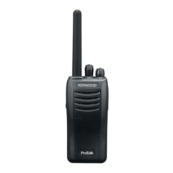
Knob (PTT)
(K29-9639-03)
Button knob (Side)
(K29-9640-03)
Plastic cabinet assy
(A02-4253-03)
T
his product complies with the RoHS directive for the European market.
Cover (Antenna)
(F07-1979-02)
Knob(Selector)
(K29-9488-03)
Knob (Volume)
(K29-9487-03)
© 2014-06 PRINTED IN JAPAN
RQ031 ( K ) B5B-7134-00
CONTENTS
GENERAL ....................................................2
REALIGNMENT ...........................................3
DISASSEMBLY FOR REPAIR .....................4
CIRCUIT DESCRIPTION .............................6
SEMICONDUCTOR DATA ...........................9
COMPONENTS DESCRIPTION ................10
PARTS LIST ...............................................11
EXPLODED VIEW ......................................17
ADJUSTMENT ...........................................18
TX-RX UNIT (X57-8992-70) ....................22
BLOCK DIAGRAM .....................................26
LEVEL DIAGRAM ......................................28
SPECIFICATIONS ......................................29
This product uses Lead Free solder
.
Advertisement
Table of Contents

Related Manuals for Kenwood TK-3501


Summary of Contents for Kenwood TK-3501
-
Page 1: Table Of Contents
UHF FM TRANSCEIVER TK-3501 SERVICE MANUAL E,T versions © 2014-06 PRINTED IN JAPAN RQ031 ( K ) B5B-7134-00 Cover (Antenna) (F07-1979-02) Knob(Selector) (K29-9488-03) Knob (Volume) (K29-9487-03) CONTENTS GENERAL ............2 REALIGNMENT ...........3 Knob (PTT) (K29-9639-03) DISASSEMBLY FOR REPAIR .....4 CIRCUIT DESCRIPTION ......6 SEMICONDUCTOR DATA ......9... -
Page 2: General
Copyright 2014 by JVC KENWOOD Corporation. All While every precaution has been taken in the preparation rights reserved. of this manual, JVC KENWOOD Corporation assumes no No part of this manual may be reproduced, translated, responsibility for errors or omissions. Neither is any liability... -
Page 3: Realignment
TK-3501 REALIGNMENT 1. Modes Note: User mode • The data stored in the personal computer must match Model Name and Model Type when it is written into EE- PROM. PC mode Data programming mode • Do not press the [PTT] key during data transmission or reception. -
Page 4: Disassembly For Repair
TK-3501 REALIGNMENT KPG-22A or KPG-22U Gray – Gray/Black 1.5D-XV Lead wire – 1.5D-XV Shield wire Tuning cable (E30-3216-05) D-SUB (9-pin) KPG-22A KPG-22U Transceiver Transceiver Fig. 1 DISASSEMBLY FOR REPAIR 1. Separating the Case Assembly from the 4. Taking care not to cut the speaker lead ( d ), open the chassis and case assembly. - Page 5 TK-3501 DISASSEMBLY FOR REPAIR 2. Removing the TX-RX unit from the 4. Removing the Antenna element Chassis When you remove an antenna element, do not give a damage to an antenna element as shown in the figure. 1. Remove the packing ( e ).
-
Page 6: Circuit Description
TK-3501 CIRCUIT DESCRIPTION 1. Frequency Configuration The receiver utilizes double conversion. The first IF is 38.85MHz and the second IF is 450kHz. The first Local os- cillator is supplied from the PLL circuit. The PLL circuit in the transmitter generates the neces- sary frequencies. - Page 7 TK-3501 CIRCUIT DESCRIPTION 3. Transmitter System 2-3. IF Amplifier Circuit The first IF signal is passed through a four-pole mono- 3-1. Microphone Amplifier Circuit lithic crystal filter (XF200) to remove the adjacent channel The signal from microphone amplified by IC301 and goes signal.
- Page 8 TK-3501 CIRCUIT DESCRIPTION 4. Frequency Synthesizer Circuit Note: The EEPROM stores tuning data (Deviation, Squelch, 4-1. Frequency Synthesizer etc.). The frequency synthesizer consists of the TCXO (X1), Realign the transceiver after replacing the EEPROM. VCO, PLL IC (IC1) and buffer amplifiers.
-
Page 9: Semiconductor Data
TK-3501 SEMICONDUCTOR DATA MCU: F2136ACNFKFMA (TX-RX unit: IC400) Pin No. Signal Name Function Pin No. Signal Name Function VOXINLEVEL VOX level input VREF Reference voltage input CV_DET VCO voltage detection MODE Mode select for MCU LSDO Low speed data output... -
Page 10: Components Description
TK-3501 COMPONENTS DESCRIPTION TX-RX unit (X57-8992-70) Ref. No. Part Name Description Q603 Transistor DC switch Ref. No. Part Name Description Q604 Transistor DC switch PLL system Diode Current steering IC200 FM IF system IC300 Variable capaci- Frequency control/ VCO tance diode... -
Page 11: Parts List
Q601 LTC043TEBFS8 TRANSISTOR Q602 2SB1132(Q,R) TRANSISTOR Q603 LTC043TEBFS8 TRANSISTOR Q604 LTC014EEBFS8 TRANSISTOR DA2J101 DIODE BBY56-02W VARIABLE CAPACITANCE DIODE BBY56-02W VARIABLE CAPACITANCE DIODE 1SS390 DIODE BBY57-02V VARIABLE CAPACITANCE DIODE BBY57-02V VARIABLE CAPACITANCE DIODE DA2J101 DIODE E: TK-3501 E T: TK-3501 T... - Page 12 CK73HB1C103K CHIP C 0.010UF C101 CC73HCH1H271J CHIP C 270PF C225 CC73HCH1H060B CHIP C 6.0PF C102 CC73HCH1H220J CHIP C 22PF C226 CK73HBB1H471K CHIP C 470PF C103 CC73GCH1H221J CHIP C 220PF C227 CK73HB1C103K CHIP C 0.010UF E: TK-3501 E T: TK-3501 T...
- Page 13 CC73HCH1H271J CHIP C 270PF C329 CK73HBB1C333K CHIP C 0.033UF C523 CC73HCH1H271J CHIP C 270PF C330 CK73HBB1H102K CHIP C 1000PF C524 CC73HCH1H271J CHIP C 270PF C332 CK73HB1C103K CHIP C 0.010UF C525 CC73HCH1H271J CHIP C 270PF E: TK-3501 E T: TK-3501 T...
- Page 14 CHIP R 1/16W R323 RK73HB1J562J CHIP R 5.6K 1/16W R324 RK73HH1J473D CHIP R 1/16W R119 RK73GB2A391J CHIP R 1/10W R325 RK73HH1J473D CHIP R 1/16W R120 RK73HB1J331J CHIP R 1/16W R327 RK73HB1J824J CHIP R 820K 1/16W E: TK-3501 E T: TK-3501 T...
- Page 15 FUSE(1.6A) R505 RK73HB1J473J CHIP R 1/16W R508 RK73HB1J473J CHIP R 1/16W CF200 L72-1046-05 CERAMIC FILTER(450KHZ) If a part reference number is listed in a shaded box, that part does not come with the PCB. E: TK-3501 E T: TK-3501 T...
- Page 16 S402 S6A-0002-00 ROTARY SWITCH(SELECTOR) TH100 B57331V2104J THERMISTOR (100K) TH260 B57331V2104J THERMISTOR (100K) J30-1308-04 SPACER (MIC) If a part reference number is listed in a shaded box, that part does not come with the PCB. E: TK-3501 E T: TK-3501 T...
-
Page 17: Exploded View
TK-3501 EXPLODED VIEW 11x4 S400 Bx13 J301 J300 MIC300 VR500 CF200 S402 CD200 TX-RX unit A : N30-2606-48 B : N83-2005-48 Parts with the exploded numbers larger than 700 are not supplied. If a part reference number is listed in a box on the exploded view of the PCB, that part does not come with the PCB. -
Page 18: Adjustment
TK-3501 ADJUSTMENT Test Equipment Required for Alignment Test Equipment Major Specifications Frequency Range 400 to 520MHz Standard Signal Generator (SSG) Modulation Frequency modulation and external modulation Output –127dBm/0.1µV to greater than –47dBm/1mV Input Impedance 50Ω RF Power Meter Operation Frequency... - Page 19 TK-3501 ADJUSTMENT Frequency and Signaling Preparations for Tuning the Transceiver The transceiver has been adjusted for the frequencies Before attempting to tune the transceiver, connect the shown in the following table. When required, re-adjust them unit to a suitable power supply.
- Page 20 TK-3501 ADJUSTMENT Common Section Measurement Adjustment Item Condition Specifications / Remarks Test- Unit Terminal Unit Parts Method equipment 1. Setting 1) BATT terminal voltage: 7.5V 2) SSG standard modulation [Narrow] MOD: 1kHz, DEV: 1.5kHz 2. VCO Lock 1) Adj item: High TX-RX ANT 2.2V...
- Page 21 TK-3501 ADJUSTMENT Measurement Adjustment Item Condition Specifications / Remarks Test- Unit Terminal Unit Parts Method equipment 7. Battery 1) BATT terminal voltage: 5.7V Power TX-RX ANT Check LED blinks Detection PTT: ON meter No transmit power Check (User mode) BATT 2) BATT terminal voltage: 7.5V...
-
Page 22: Pc Board
TK-3501 PC BOARD TX-RX UNIT (X57-8992-70) Component side view (J79-0423-09) C322 R367 R392 R360 C345 C329 C523 R393 C134 – C139 MIC30 C353 C517 C355 R136 C326 R340 R120 R329 C319 R377 C317 C354 Q103 R327 C360 D402 C525 R455... - Page 23 TK-3501 PC BOARD TX-RX UNIT (X57-8992-70) Component side view (J79-0423-09) Q603 Q604 R408 C411 C514 R606 R407 – C506 R604 R509 C502 C515 Q601 C507 IC503 MIC300 IC500 Q602 Q301 R502 C505 C513 C312 C504 C306 C522 C602 R505 C307...
- Page 24 TK-3501 PC BOARD TX-RX UNIT (X57-8992-70) Foil side view (J79-0423-09) S401 CN104 S400 Side C300 CN101 C103 C138 C136 C132 C135 C127 L111 C271 L104 L110 C250 C119 C116 C120 C279 C269 C117 C413 C415 C268 C280 Q204 C240 L208...
- Page 25 TK-3501 PC BOARD TX-RX UNIT (X57-8992-70) Foil side view (J79-0423-09) C300 R106 C113 R108 R113 C110 C114 C103 L102 C108 C154 L117 L116 C112 L104 L100 C119 C116 R100 C120 C117 L214 D100 C257 C258 R221 R218 Q203 C276 R220...
-
Page 26: Block Diagram
TK-3501 BLOCK DIAGRAM X57-8992-70 MB15E03SL-E1 PLLPS 446.000MHz~446.100MHz (TX) 407.150MHz~407.250MHz (RX) PLLEN DATA Q4 :MCH3914(7)-H 2SC5108(Y)F 2SC4726(P,Q) D2,3:BBY56-02V CLOCK RF BUFFER RF AMP D6:BBY57-02V LTC014EEBFS8 3.3V REG D5:BBY57-02V Q3:LSCR523EBFS8 LSCR523EBFS8 Q2:LTC043ZEBFS8 TUNE D7:DA2J101 D4:1SS390 PLLLD F500 19.2MHz RIPPLE BATT+ SHIFT SW... - Page 27 TK-3501 BLOCK DIAGRAM 446.000MHz~ 446.100MHz 446.000MHz~446.100MHz (TX) 407.150MHz~407.250MHz (RX) D100,D200 Q101 Q102 D102,103 2SC5108(Y)F 2SC4726(P,Q) 1SS390 RFM01U7P RN262CS RFM01U7P RF BUFFER TX/RX RF AMP DRIVE AMP FINAL AMP ANT SW RF SW POWC Q3:LSCR523EBFS8 EBFS8 D7:DA2J101 RIPPLE VDCSW VDC SW...
-
Page 28: Level Diagram
TK-3501 LEVEL DIAGRAM... -
Page 29: Specifications
Spurious Emission ..........–36dBm (30MHz~1GHz) –30dBm (1GHz~4GHz) Modulation Distortion ..........Less than 5% FM Noise ...............40dB Modulation .............8K50F3E Measurements made per EN standards or TIA/EIA 603 and specifications shown are typical. JVC KENWOOD Corporation reserves the right to change specifications without prior notice or obligation. - Page 30 TK-3501 JVC KENWOOD Corporation Communications Equipment BU...
-
Page 31: Appendix
TK-3501 TX-RX UNIT (X57-8992-70) APPENDIX L111 L112 CN111 FINAL C103 L118 Strip Line C127 D102 C131 C135 DRIVE Q 102 C137 (SCHEMATIC DIAGRAM X57-899) RF M01U7P L116 220p 180p RN262CS 180p Q 101 C112 (-53) CN112 RF M01U7P R:1.03V L102 D2,D3,D5 T:1.69V... - Page 32 TK-3501 TK-3501 PC BOARD PC BOARD TX-RX UNIT (X57-8992-70) Component side view (J79-0423-09) TX-RX UNIT (X57-8992-70) Component side view (J79-0423-09) Q603 C322 R367 R392 Q604 R360 C345 R408 C411 C329 C523 C514 R606 R407 R393 C134 – C506 R604 R509...
- Page 33 TK-3501 TK-3501 PC BOARD PC BOARD TX-RX UNIT (X57-8992-70) Foil side view (J79-0423-09) TX-RX UNIT (X57-8992-70) Foil side view (J79-0423-09) S401 CN104 S400 Side C300 CN101 R106 C113 R108 R113 C110 C114 C138 C136 C132 C103 L102 C108 C154 C135...
- Page 34 X57-8992-70 446.000MHz~ 446.100MHz MB15E03SL-E1 446.000MHz~446.100MHz (TX) PLLPS 407.150MHz~407.250MHz (RX) PLLEN DATA Q4 :MCH3914(7)-H D100,D200 Q101 Q102 D102,103 2SC5108(Y)F 2SC4726(P,Q) 1SS390 RFM01U7P RN262CS D2,3:BBY56-02V RFM01U7P CLOCK RF BUFFER TX/RX D6:BBY57-02V RF AMP DRIVE AMP FINAL AMP ANT SW RF SW LTC014EEBFS8 3.3V REG POWC D5:BBY57-02V...