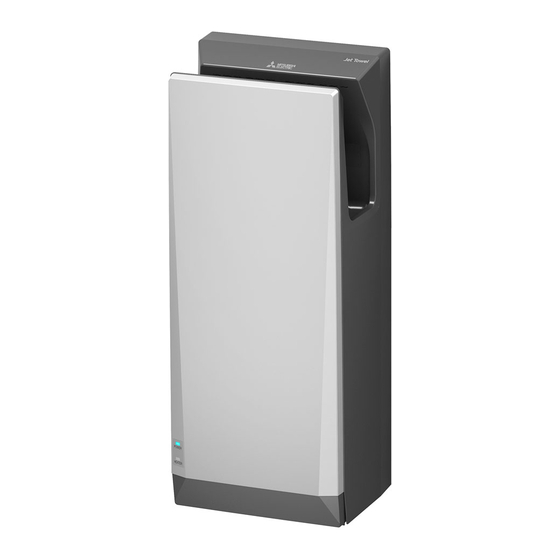
Mitsubishi Electric Jet Towel JT-SB216JSH2-S-NE Installation Manual
Hide thumbs
Also See for Jet Towel JT-SB216JSH2-S-NE:
- Handbook (57 pages) ,
- Instruction manual (13 pages)
Table of Contents
Advertisement
Quick Links
MODEL
JT-SB216JSH2-W-NE
JT-SB216JSH2-H-NE
JT-SB216JSH2-S-NE
JT-SB216KSN2-W-NE Heater-less Model
Appliance color -W
INSTALLATION MANUAL
Read this manual thoroughly before beginning installation to ensure the appliance is installed safely and correctly.
Local installation standards should be obeyed and installation should be performed by the dealer or a qualifi ed
professional.
The "INSTRUCTION MANUAL" is for the customer. Be sure to hand it to the customer.
INDEX
Safety Precautions ............................................................ 2
Pre-installation checks ...................................................... 3
Names of parts and external dimensions .............................. 4
Installation conditions ......................................................... 5
Installation method ...................................................... 6~10
Test Run ........................................................................ 11
Hand dryer
Heater Model
, -H
, -S
(White)
(Dark grey)
....................................... 3
............................................. 5
............................................................... 5
....................................... 5
(Silver)
For Dealers and Installers
− 1 −
1509876HC2301
Model Name
Display Position
Power voltage
display position.
Single-phase 220-240V AC
... 3
GB
Advertisement
Table of Contents

Related Manuals for Mitsubishi Electric Jet Towel JT-SB216JSH2-S-NE


Summary of Contents for Mitsubishi Electric Jet Towel JT-SB216JSH2-S-NE
-
Page 1: Table Of Contents
1509876HC2301 Hand dryer MODEL Model Name Display Position JT-SB216JSH2-W-NE Heater Model Power voltage display position. JT-SB216JSH2-H-NE JT-SB216JSH2-S-NE JT-SB216KSN2-W-NE Heater-less Model Appliance color -W , -H , -S (White) (Dark grey) (Silver) Single-phase 220-240V AC INSTALLATION MANUAL For Dealers and Installers Read this manual thoroughly before beginning installation to ensure the appliance is installed safely and correctly. -
Page 2: Safety Precautions
Safety Precautions Warning The following may lead to death or serious personal injury if the appliance is handled incorrectly. Do not install in locations where salt Electrical wiring work should be done by a damage may occur, or where corrosive, certifi... -
Page 3: Pre-Installation Checks
Pre-installation checks ■ Checking the installation environment Do not install in the following types of location. (This may cause malfunctions.) Outdoors Locations where the temperature could be lower than 0ºC. Locations where there is a lot of dust Locations where the temperature could be higher than 40ºC Locations where there is a lot of condensation Locations where salt damage could occur Vehicles (including ships and airplanes) -
Page 4: Names Of Parts And External Dimensions
Names of parts and external dimensions Terminal block Installation panel Power cable hole (rear) Terminal block Drain tank Air fi lter (air intake) (79.5) (103.5) ※ ※ Maximum width Unit (mm) of main unit ■ Front Terminal block Front panel Display Front panel Heater type (JSH2) -
Page 5: Installation Conditions
Installation conditions ■ Required space for installation Wall Be sure to secure at least the distances Cautions listed in the right-hand table from walls, Right flammable (combustible) materials and Left so on. Location Clearance Ensure a distance of at least 130mm from the floor. -
Page 6: Installation Method
Installation method Caution Warning Use single-phase 220-240V power. Do not install when the product (power cable) is electrifi ed. Using the incorrect power supply may cause fi res, electric shocks or malfunctions. Doing so may result in electric shocks. Check □... - Page 7 Installation (Continued) 1. Remove the drain tank and air fi lter. Drain tank Air fi lter 2. Remove the front panel mounting screws (2), Front panel mounting screws Groove and remove the front panel. Front panel 3. Remove the terminal cover mounting screw (1), and remove the terminal cover.
- Page 8 Installation (Continued) Warning Use single-phase 220-240V power. Using the incorrect power supply may cause fi res, electric shocks or malfunctions. Wire it to the terminal block. (No polarity) Unit (mm) 1. Remove 12mm (single wire) or 8mm (stranded wire) of wire sheath from the Single wire ■...
- Page 9 Installation (Continued) Terminal Move the power block 1. Run the power cable through the rubber cable to the left side of the bushing, and attach the rubber bushing to terminal cover. the terminal cover. Terminal cover 2. Attach the terminal cover to the main unit mounting screw using the terminal cover mounting screw.
- Page 10 ■ Switching the air speed switch and heater switch settings Check the heater ON/OFF settings and air speed HIGH/STANDARD settings with the customer beforehand. (The user cannot adjust the settings after installation is complete.) (The JT-SB216KSN2-W-NE does not have a heater switch.) Do not install when the product (power cord) is electrifi...
-
Page 11: Test Run
1 minute before switching the ground-fault circuit interrupter back "ON". HEAD OFFICE: TOKYO BLDG., 2-7-3, MARUNOUCHI, CHIYODA-KU, TOKYO 100-8310, JAPAN AUTHORIZED REPRESENTATIVE IN EU: MITSUBISHI ELECTRIC EUROPE B.V. HARMAN HOUSE, 1 GEORGE STREET, UXBRIDGE, MIDDLESEX UB8 1QQ, U.K. − 11 −... - Page 12 2006/66/EC Article 20 Information for end-users and Annex II. Français English Votre produit Mitsubishi Electric est conçu et fabriqué avec des matériels et des composants de qualité supérieure qui peuvent être Your MITSUBISHI ELECTRIC product is designed and recyclés et/ou réutilisés.
- Page 13 Dansk Mitsubishi Electric producten zijn ontwikkeld en gefabriceerd uit eerste kwaliteit materialen. De onderdelen kunnen worden Dit produkt fra MITSUBISHI ELECTRIC er designet og fremstillet gerecycled en/of worden hergebruikt. med kvalitetsmaterialer og komponenter, der kan genindvindes og/ Het symbool betekent dat de elektrische en elektronische eller genbruges.
- Page 14 Mitsubishi Electric Corporation Head Office: Tokyo Bldg., 2-7-3, Marunouchi, Chiyoda-ku, Tokyo 100-8310, Japan Manufacturer Authorised representative in EU: Mitsubishi Electric Europe B.V.: 1 George Street, Harman House, Uxbridge, Middlesex, UB81QQ Commercial registration no. 33279602 Motor Power Input (kW) 0.66 Flow Rate (m 0.05...
- Page 15 Wiring Diagram Diagramme de câblage 接线图 接線圖 배선도 Current fuse in control circuit Fusibles à intensité du circuit de commande FUSE1, 2 ... 250 V - 20 A FUSE3 ..250 V - 3.15 A 控制电路內的电流保险丝 控制電路內的電流保險絲 제어 회로의 전류 퓨즈 Thermal fuse fusion temperature Température de fusion du fusible thermique 温度保险丝熔断温度...