
Related Manuals for Honeywell Xenon 1500


Summary of Contents for Honeywell Xenon 1500
- Page 1 Xenon™ 1500 Area-Imaging Scanner User’s Guide ™ http://manualforhoneywellthermostat.com...
- Page 2 Disclaimer Honeywell International Inc. (“HII”) reserves the right to make changes in speci- fications and other information contained in this document without prior notice, and the reader should in all cases consult HII to determine whether any such changes have been made. The information in this publication does not repre- sent a commitment on the part of HII.
- Page 3 The user may find the fol- lowing booklet helpful: “Something About Interference.” This is available at FCC local regional offices. Honeywell is not responsible for any radio or television interference caused by unauthorized modifications of this equip- ment or the substitution or attachment of connecting cables and equipment other than those specified by Honeywell.
- Page 4 Nijverheidsweg 9-13 5627 BT Eindhoven The Netherlands Honeywell International Inc. shall not be liable for use of our product with equipment (i.e., power supplies, personal computers, etc.) that is not CE marked and does not comply with the Low Voltage Directive.
- Page 5 In order to avoid the dissemination of those substances in our environment and to diminish the pressure on the natural resources, we encourage you to use the appropriate take-back systems for product disposal. Those sys- tems will reuse or recycle most of the materials of the product you are dis- posing in a sound way.
- Page 6 Patents For patent information, please refer to www.honeywellaidc.com/patents. Solids and Water Protection The Xenon 1500 has a rating of IP41, immunity of foreign particles and dripping water. Warning To reduce the possibility of heat-related injuries, avoid touching sec- tions of the scanner that feel warm.
- Page 7 Required Safety Labels Scanner Illumination output Part Number, Serial Compliance Number and Label Revision location Information location...
-
Page 9: Table Of Contents
Table of Contents Chapter 1 - Getting Started About This Manual ............1-1 Unpacking Your Device..........1-1 Connecting the Device with USB ........ 1-2 Reading Techniques ........... 1-2 Setting Custom Defaults ..........1-3 Resetting the Custom Defaults ........1-4 Resetting the Factory Defaults ........1-5 Chapter 2 - Programming the Interface Introduction .............. - Page 10 Number of Beeps – Good Read ......3-4 Number of Beeps – Error ........3-4 Good Read Delay ..........3-5 User-Specified Good Read Delay......3-5 Manual Trigger Mode...........3-5 Serial Trigger Mode .............3-5 Read Time-Out ............3-6 Presentation Mode............3-6 Presentation LED Behavior after Decode ....3-6 Presentation Sensitivity .........
- Page 11 Intercharacter Delay ..........4-5 User Specified Intercharacter Delay...... 4-5 Interfunction Delay ..........4-6 Intermessage Delay ..........4-6 Chapter 5 - Data Formatting Data Format Editor Introduction ........5-1 Add a Data Format ............5-1 Other Programming Selections ......5-3 Terminal ID Table............5-4 Data Format Editor Commands ........
- Page 12 UPC-A................6-21 UPC-A/EAN-13 with Extended Coupon Code........6-23 Coupon GS1 DataBar Output ........6-23 UPC-E0..............6-24 UPC-E1..............6-27 EAN/JAN-13 ..............6-27 ISBN Translate ............ 6-29 EAN/JAN-8 ..............6-30 MSI ................6-32 GS1 DataBar Omnidirectional ........6-34 GS1 DataBar Limited..........6-34 GS1 DataBar Expanded ..........6-35 Codablock A ..............6-36 Codablock F...............6-37 PDF417..............6-38 MacroPDF417............6-39 MicroPDF417.............6-39 GS1 Composite Codes ..........6-40...
- Page 13 Chapter 8 - Utilities To Add a Test Code I.D. Prefix to All Symbologies ............. 8-1 Show Decoder Revision ..........8-1 Show Scan Driver Revision......... 8-1 Show Software Revision ..........8-1 Show Data Format ............8-2 Test Menu ..............8-2 TotalFreedom ..............
- Page 14 Replacing Cables in Corded Scanners......11-2 Replacing an Interface Cable ......11-3 Troubleshooting a Xenon Scanner ......11-3 Chapter 12 - Customer Support Appendix A - Reference Charts Symbology Chart ............A-1 ASCII Conversion Chart (Code Page 1252) ....A-4 Code Page Mapping of Printed Bar Codes....A-6 Unicode Key Maps............
-
Page 15: Chapter 1 - Getting Started
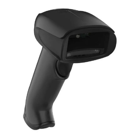
Xenon™ 1500 area-imaging scanner. Product specifications, dimensions, war- ranty, and customer support information are also included. Honeywell bar code scanners are factory programmed for the most common terminal and communications settings. If you need to change these settings, programming is accomplished by scanning the bar codes in this guide. -
Page 16: Connecting The Device With Usb
Connecting the Device with USB The scanner can be connected to the USB port of a computer. Connect the appropriate interface cable to the device first, then to the computer. Reading Techniques The scanner has a view finder that projects a bright red aiming beam that corre- sponds to the scanner’s horizontal field of view. -
Page 17: Setting Custom Defaults
Linear bar code 2D Matrix symbol The aiming beam is smaller when the scanner is closer to the code and larger when it is farther from the code. Symbologies with smaller bars or elements (mil size) should be read closer to the unit. Symbologies with larger bars or ele- ments (mil size) should be read farther from the unit. -
Page 18: Resetting The Custom Defaults
entire sequence will be saved to your custom defaults. When you have entered all the commands you want to save for your custom defaults, scan the Save Custom Defaults bar code. Set Custom Defaults Save Custom Defaults You may have a series of custom settings and want to correct a single setting. To do so, just scan the new setting to overwrite the old one. -
Page 19: Resetting The Factory Defaults
Resetting the Factory Defaults This selection erases all your settings and resets the scanner to the original factory defaults. It also disables all plugins . If you aren’t sure what programming options are in your scanner, or you’ve changed some options and want to restore the scanner to factory default set- tings, first scan the Remove Custom Defaults bar code, then scan Activate Defaults. - Page 20 1 - 6...
-
Page 21: Chapter 2 - Programming The Interface
Programming the Interface Introduction This chapter describes how to program your system for the desired interface. Programming the Interface - Plug and Play Note: After you scan one of the codes, power cycle the host terminal to have the interface in effect. USB IBM SurePos Scan one of the following “Plug and Play”... -
Page 22: Usb Pc Or Macintosh Keyboard
Scan the following code to program the scanner to emulate a regular RS232-based COM Port. If you are using a Microsoft® Windows® PC, you will need to download a driver from the Honeywell website (www.honeywellaidc.com). The driver will use the next available COM Port number. - Page 23 CTS/RTS Emulation CTS/RTS Emulation On * CTS/RTS Emulation Off ACK/NAK Mode ACK/NAK Mode On * ACK/NAK Mode Off 2 - 3...
-
Page 24: Keyboard Country Layout
Keyboard Country Layout Scan the appropriate country code below to program the keyboard layout for your country or language. As a general rule, the following characters are sup- ported, but need special care for countries other than the United States: @ | $ # { } [ ] = / ‘... - Page 25 Keyboard Country (continued) Brazil (MS) Bulgaria (Cyrillic) Bulgaria (Latin) Canada (French legacy) Canada (French) Canada (Multilingual) Croatia Czech Czech (Programmers) Czech (QWERTY) Czech (QWERTZ) Denmark Dutch (Netherlands) 2 - 5...
- Page 26 Keyboard Country (continued) Estonia Faeroese Finland France Gaelic Germany Greek Greek (220 Latin) Greek (220) Greek (319 Latin) Greek (319) Greek (Latin) Greek (MS) 2 - 6...
- Page 27 Keyboard Country (continued) Greek (Polytonic) Hebrew Hungarian (101 key) Hungary Iceland Irish Italian (142) Italy Japan ASCII Kazakh Kyrgyz (Cyrillic) Latin America Latvia 2 - 7...
- Page 28 Keyboard Country (continued) Latvia (QWERTY) Lithuania Lithuania (IBM) Macedonia Malta Mongolian (Cyrillic) Norway Poland Polish (214) Polish (Programmers) Portugal Romania Russia 2 - 8...
- Page 29 Keyboard Country (continued) Russian (MS) Russian (Typewriter) Serbia (Cyrillic) Serbia (Latin) Slovakia Slovakia (QWERTY) Slovakia (QWERTZ) Slovenia Spain Spanish variation Sweden Switzerland (French) 2 - 9...
-
Page 30: Keyboard Style
Keyboard Country (continued) Switzerland (German) Tatar Turkey F Turkey Q Ukrainian United Kingdom United Stated (Dvorak right) United States (Dvorak left) United States (Dvorak) United States (International) Uzbek (Cyrillic) Keyboard Style This programs keyboard styles, such as Caps Lock and Shift Lock. If you have used Keyboard Conversion settings, they will override any of the following Key-... - Page 31 Regular is used when you normally have the Caps Lock key off. * Regular Caps Lock is used when you normally have the Caps Lock key on. Caps Lock Shift Lock is used when you normally have the Shift Lock key on (not common to U.S.
-
Page 32: Keyboard Conversion
Keyboard Conversion Alphabetic keyboard characters can be forced to be all upper case or all lower- case. So if you have the following bar code: “abc569GK,” you can make the output “ABC569GK” by scanning Convert All Characters to Upper Case, or to “abc569gk”... - Page 33 Control + ASCII Mode On: The scanner sends key combinations for ASCII control characters for values 00-1F. Windows is the preferred mode. All key- board country codes are supported. DOS mode is a legacy mode, and it does not support all keyboard country codes. New users should use the Windows mode.
- Page 34 Numeric Keypad Mode: Sends numeric characters as if entered from a numeric keypad. Default = Off. Numeric Keypad Mode On * Numeric Keypad Mode Off 2 - 14...
-
Page 35: Chapter 3 - Input/Output Settings
Input/Output Settings Power Up Beeper The scanner can be programmed to beep when it’s powered up. Scan the Off bar code(s) if you don’t want a power up beep. Default = Power Up Beeper On - Scanner. Power Up Beeper Off * Power Up Beeper On Beep on BEL Character You may wish to force the scanner to beep upon a command sent from the host. -
Page 36: Good Read And Error Indicators
Good Read and Error Indicators Beeper – Good Read The beeper may be programmed On or Off in response to a good read. Turning this option off, only turns off the beeper response to a good read indication. All error and menu beeps are still audible. Default = Beeper - Good Read On. -
Page 37: Beeper Pitch - Good Read
Beeper Pitch – Good Read The beeper pitch codes modify the pitch (frequency) of the beep the scan- ner emits on a good read. Default = Medium. Low (1600 Hz) * Medium (2700 Hz) High (4200 Hz) Beeper Pitch – Error The beeper pitch codes modify the pitch (frequency) of the sound the scan- ner emits when there is a bad read or error. -
Page 38: Led - Good Read
LED – Good Read The LED indicator can be programmed On or Off in response to a good read. Default = On. * LED - Good Read On LED - Good Read Off Number of Beeps – Good Read The number of beeps of a good read can be programmed from 1 - 9. The same number of beeps will be applied to the beeper and LED in response to a good read. -
Page 39: Good Read Delay
Good Read Delay This sets the minimum amount of time before the scanner can read another bar code. Default = 0 ms (No Delay). * No Delay Short Delay (500 ms) Medium Delay (1,000 ms) Long Delay (1,500 ms) User-Specified Good Read Delay If you want to set your own length for the good read delay, scan the bar code below, then set the delay (from 0-30,000 milliseconds) by scanning digits from the inside back cover, then scanning Save. -
Page 40: Read Time-Out
Read Time-Out Use this selection to set a time-out (in milliseconds) of the scanner’s trigger when using serial commands to trigger the scanner. Once the scanner has timed out, you can activate the scanner either by pressing the trigger or using a serial trigger command. -
Page 41: Presentation Sensitivity
Presentation Sensitivity Presentation Sensitivity is a numeric range that increases or decreases the scanner's reaction time to bar code presentation. To set the sensitivity, scan the Sensitivity bar code, then scan the degree of sensitivity (from 0- 20) from the inside back cover, and Save. 0 is the most sensitive setting, and 20 is the least sensitive. - Page 42 In the example below, the white box is the centering window. The centering window has been set to 20% left, 30% right, 8% top, and 25% bottom. Since Bar Code 1 passes through the centering window, it will be read. Bar Code 2 does not pass through the centering window, so it will not be read.
-
Page 43: Mobile Phone Read Mode
Scan Presentation Centering On, then scan one of the following bar codes to change the top, bottom, left, or right of the centering window. Then scan the percent you want to shift the centering window using digits on the inside back cover of this manual. Scan Save. Default Presentation Centering = 40% for Top and Left, 60% for Bottom and Right. -
Page 44: Hands Free Time-Out
Hands Free Time-Out The Presentation Modes are referred to as “hands free” modes. If the scanner’s trigger is pulled when using a hands free mode, the scanner changes to manual trigger mode. You can set the time the scanner should remain in manual trigger mode by setting the Hands Free Time-Out. -
Page 45: User-Specified Reread Delay
User-Specified Reread Delay If you want to set your own length for the reread delay, scan the bar code below, then set the delay (from 0-30,000 milliseconds) by scanning digits from the inside back cover, then scanning Save. User-Specified Reread Delay Illumination Lights If you want the illumination lights on while reading a bar code, scan the Lights On bar code, below. -
Page 46: User-Specified Aimer Delay
User-Specified Aimer Delay If you want to set your own length for the duration of the delay, scan the bar code below, then set the time-out by scanning digits (0 - 4,000 ms) from the Programming Chart inside the back cover of this manual, then scan Save. Delay Duration Scanner Time-Out Scanner Time-Out powers down the scanner after the unit has been idle for the... - Page 47 multiple codes are spaced closely together. Using the Aimer Delay and Center- ing features, the scanner can emulate the operation of older systems, such as linear laser bar code scanners.) Note: To adjust centering when the scanner is in the stand, see Presentation Centering (page 3-7).
-
Page 48: No Read
Scan Centering On, then scan one of the following bar codes to change the top, bottom, left, or right of the centering window. Then scan the percent you want to shift the centering window using digits on the inside back cover of this manual. -
Page 49: Video Reverse
Video Reverse Video Reverse is used to allow the scanner to read bar codes that are inverted. The Video Reverse Off bar code below is an example of this type of bar code. Scan Video Reverse Only to read only inverted bar codes. Scan Video Reverse and Standard Bar Codes to read both types of codes. - Page 50 Default = Upright. * Upright Vertical, Bottom to Top Upside Down Vertical, Top to Bottom 3 - 16...
-
Page 51: Chapter 4 - Data Editing
Data Editing Prefix/Suffix Overview When a bar code is scanned, additional information is sent to the host computer along with the bar code data. This group of bar code data and additional, user-defined data is called a “message string.” The selections in this section are used to build the user-defined data into the message string. -
Page 52: To Clear One Or All Prefixes Or Suffixes
symbology to which you want to apply the prefix or suffix. For example, for Code 128, Code ID is “j” and Hex ID is “6A”. Step 3. Scan the 2 hex digits from the Programming Chart inside the back cover of this manual or scan 9, 9 for all symbologies. Step 4. -
Page 53: To Add A Carriage Return Suffix To All Symbologies
Step 1. Scan the Clear One Prefix or Clear One Suffix symbol. Step 2. Determine the 2 digit Hex value from the Symbology Chart (included in the Symbology Chart, beginning on page A-1) for the symbology from which you want to clear the prefix or suffix. Step 3. -
Page 54: Suffix Selections
Suffix Selections Add Suffix Clear One Suffix Clear All Suffixes Function Code Transmit When this selection is enabled and function codes are contained within the scanned data, the scanner transmits the function code to the terminal. Charts of these function codes are provided in Supported Interface Keys starting on page... -
Page 55: Intercharacter Delay
Intercharacter Delay An intercharacter delay of up to 5000 milliseconds (in 5ms increments) may be placed between the transmission of each character of scanned data. Scan the Intercharacter Delay bar code below, then scan the number of 5ms delays, and the Save bar code using the Programming Chart inside the back cover of this manual. -
Page 56: Interfunction Delay
Interfunction Delay An interfunction delay of up to 5000 milliseconds (in 5ms increments) may be placed between the transmission of each segment of the message string. Scan the Interfunction Delay bar code below, then scan the num- ber of 5ms delays, and the Save bar code using the Programming Chart inside the back cover of this manual. -
Page 57: Chapter 5 - Data Formatting
Data Formatting Data Format Editor Introduction You may use the Data Format Editor to change the scanner’s output. For exam- ple, you can use the Data Format Editor to insert characters at certain points in bar code data as it is scanned. The selections in the following pages are used only if you wish to alter the output. - Page 58 you are programming. (See Primary/Alternate Data Formats on page 5-8 for further information.) Step 3. Terminal Type Refer to Terminal ID Table (page 5-4) and locate the Terminal ID number for your PC. Scan three numeric bar codes on the inside back cover to program the scanner for your terminal ID (you must enter 3 digits).
-
Page 59: Other Programming Selections
Other Programming Selections Clear One Data Format This deletes one data format for one symbology. If you are clearing the primary format, scan 0 from the Programming Chart inside the back cover of this manual. If you are clearing an alternate format, scan 1, 2, or 3, depending on the format you are clearing. -
Page 60: Terminal Id Table
Terminal ID Table Terminal Terminal Model(s) USB SurePOS Handheld Scanner USB SurePOS Tabletop Scanner Serial PC Keyboard Mac Keyboard Japanese Keyboard (PC) HID POS Data Format Editor Commands Send Commands Send all characters F1 Include in the output message all of the characters from the input message, starting from current cursor position, followed by an insert character. -
Page 61: Move Commands
Send all but the last characters E9 Include in the output message all but the last “nn” characters, starting from the current cursor position. The cursor is moved forward to one position past the last input message character included. Syntax = E9nn where nn stands for the numeric value (00-99) for the number of characters that will not be sent at the end of the message. -
Page 62: Miscellaneous Commands
Search backward for a character F9 Search the input message backward for “xx” character from the current cursor position, leaving the cursor pointing to the “xx” character. Syntax = F9xx where xx stands for the search character’s hex value for its ASCII code. -
Page 63: Data Formatter
Stop replacing characters E5 Terminates character replacement. Syntax = E5. Compare characters FE Compare the character in the current cursor position to the character “xx.” If characters are equal, move the cursor forward one position. Syntax = FExx where xx stands for the comparison character’s hex value for its ASCII code. -
Page 64: Primary/Alternate Data Formats
Default = Data Formatter On, Not Required. * Data Formatter On, Not Required Data Format Required Primary/Alternate Data Formats You can save up to four data formats, and switch between these formats. Your primary data format is saved under 0. Your other three formats are saved under 1, 2, and 3. - Page 65 Symbologies This programming section contains the following menu selections. Refer to Chapter 9 for settings and defaults. • All Symbologies • GS1-128 • Aztec Code • Interleaved 2 of 5 • China Post (Hong Kong 2 of 5) • Korea Post •...
-
Page 66: All Symbologies
All Symbologies If you want to decode all the symbologies allowable for your scanner, scan the All Symbologies On code. If on the other hand, you want to decode only a particular symbology, scan All Symbologies Off followed by the On symbol for that particular symbology. -
Page 67: Codabar
Codabar <Default All Codabar Settings> Codabar On/Off * On Codabar Start/Stop Characters Start/Stop characters identify the leading and trailing ends of the bar code. You may either transmit, or not transmit Start/Stop characters. Default = Don’t Transmit . Transmit * Don’t Transmit Codabar Check Character Codabar check characters are created using different “modulos.”... -
Page 68: Codabar Concatenation
When Check Character is set to Validate, but Don’t Transmit , the unit will only read Codabar bar codes printed with a check character, but will not transmit the check character with the scanned data. * No Check Character Validate Modulo 16, but Don’t Transmit Validate Modulo 16 and Transmit... - Page 69 Codabar Message Length Scan the bar codes below to change the message length. Refer to Message Length Description (page 6-2) for additional information. Mini- mum and Maximum lengths = 2-60. Minimum Default = 4, Maximum Default = 60. Minimum Message Length Maximum Message Length 6 - 5...
-
Page 70: Code 39
Code 39 < Default All Code 39 Settings > Code 39 On/Off * On Code 39 Start/Stop Characters Start/Stop characters identify the leading and trailing ends of the bar code. You may either transmit, or not transmit Start/Stop characters. Default = Don’t Transmit. - Page 71 When Check Character is set to Validate and Transmit, the scanner only reads Code 39 bar codes printed with a check character, and will transmit this character at the end of the scanned data. Default = No Check Charac- ter. * No Check Character Validate, but Don’t Transmit Validate and Transmit...
-
Page 72: Full Ascii
acter(s), it buffers Code 39 bar codes until it reads a Code 39 bar code that does not have the append trigger. The data is then transmitted in the order in which the bar codes were read (FIFO). Default = Off. * Off Full ASCII If Full ASCII Code 39 decoding is enabled, certain character pairs within... -
Page 73: Code 39 Code Page
Character pairs /M and /N decode as a minus sign and period respectively. Character pairs /P through /Y decode as 0 through 9. Full ASCII On * Full ASCII Off Code 39 Code Page Code pages define the mapping of character codes to characters. If the data received does not display with the proper characters, it may be because the bar code being scanned was created using a code page that is different from the one the host program is expecting. -
Page 74: Interleaved 2 Of 5
Interleaved 2 of 5 < Default All Interleaved 2 of 5 Settings > Interleaved 2 of 5 On/Off * On Check Digit No Check Digit indicates that the scanner reads and transmits bar code data with or without a check digit. When Check Digit is set to Validate, but Don’t Transmit, the unit only reads Interleaved 2 of 5 bar codes printed with a check digit, but will not transmit the check digit with the scanned data. -
Page 75: Nec 2 Of 5
Interleaved 2 of 5 Message Length Scan the bar codes below to change the message length. Refer to Message Length Description (page 6-2) for additional information. Mini- mum and Maximum lengths = 2-80. Minimum Default = 4, Maximum Default = 80. Minimum Message Length Maximum Message Length NEC 2 of 5... - Page 76 When Check Digit is set to Validate and Transmit, the scanner only reads NEC 2 of 5 bar codes printed with a check digit, and will transmit this digit at the end of the scanned data. Default = No Check Digit. * No Check Digit Validate, but Don’t Transmit Validate and Transmit...
-
Page 77: Code 93
Code 93 < Default All Code 93 Settings > Code 93 On/Off * On Code 93 Message Length Scan the bar codes below to change the message length. Refer to Message Length Description (page 6-2) for additional information. Mini- mum and Maximum lengths = 0-80. Minimum Default = 0, Maximum Default = 80. -
Page 78: Code 93 Code Page
which the bar codes are read, deleting the first space from each. The scanner transmits the appended data when it reads a Code 93 bar code that starts with a character other than a space. Default = Off. * Off Code 93 Code Page Code pages define the mapping of character codes to characters. -
Page 79: Straight 2 Of 5 Industrial (Three-Bar Start/Stop)
Straight 2 of 5 Industrial (three-bar start/stop) <Default All Straight 2 of 5 Industrial Settings> Straight 2 of 5 Industrial On/Off * Off Straight 2 of 5 Industrial Message Length Scan the bar codes below to change the message length. Refer to Message Length Description (page 6-2) for additional information. -
Page 80: Straight 2 Of 5 Iata (Two-Bar Start/Stop)
Straight 2 of 5 IATA (two-bar start/stop) <Default All Straight 2 of 5 IATA Settings> Straight 2 of 5 IATA On/Off * Off Straight 2 of 5 IATA Message Length Scan the bar codes below to change the message length. Refer to Message Length Description (page 6-2) for additional information. -
Page 81: Matrix 2 Of 5
Matrix 2 of 5 <Default All Matrix 2 of 5 Settings> Matrix 2 of 5 On/Off * Off Matrix 2 of 5 Message Length Scan the bar codes below to change the message length. Refer to Message Length Description (page 6-2) for additional information. Mini- mum and Maximum lengths = 1-80. -
Page 82: Code 128
Code 128 <Default All Code 128 Settings> Code 128 On/Off * On ISBT 128 Concatenation In 1994 the International Society of Blood Transfusion (ISBT) ratified a standard for communicating critical blood information in a uniform manner. The use of ISBT formats requires a paid license. The ISBT 128 Application Specification describes 1) the critical data elements for labeling blood prod- ucts, 2) the current recommendation to use Code 128 due to its high degree of security and its space-efficient design, 3) a variation of Code 128... -
Page 83: Code 128 Code Page
Code 128 Message Length Scan the bar codes below to change the message length. Refer to Message Length Description (page 6-2) for additional information. Mini- mum and Maximum lengths = 0-80. Minimum Default = 0, Maximum Default = 80. Minimum Message Length Maximum Message Length Code 128 Append This function allows the scanner to append the data from several Code 128... -
Page 84: Gs1-128
GS1-128 <Default All GS1-128 Settings> GS1-128 On/Off * On GS1-128 Message Length Scan the bar codes below to change the message length. Refer to Message Length Description (page 6-2) for additional information. Mini- mum and Maximum lengths = 1-80. Minimum Default = 1, Maximum Default = 80. -
Page 85: Upc-A
UPC-A <Default All UPC-A Settings> UPC-A On/Off * On UPC-A Check Digit This selection allows you to specify whether the check digit should be transmitted at the end of the scanned data or not. Default = On . * On UPC-A Number System The numeric system digit of a U.P.C. - Page 86 UPC-A Addenda This selection adds 2 or 5 digits to the end of all scanned UPC-A data. Default = Off for both 2 Digit and 5 Digit Addenda. 2 Digit Addenda On * 2 Digit Addenda Off 5 Digit Addenda On * 5 Digit Addenda Off UPC-A Addenda Required When Required is scanned, the scanner will only read UPC-A bar codes...
-
Page 87: Upc-A/Ean-13
UPC-A/EAN-13 with Extended Coupon Code Use the following codes to enable or disable UPC-A and EAN-13 with Extended Coupon Code. When left on the default setting (Off), the scanner treats Cou- pon Codes and Extended Coupon Codes as single bar codes. If you scan the Allow Concatenation code, when the scanner sees the coupon code and the extended coupon code in a single scan, it transmits both as sepa- rate symbologies. -
Page 88: Upc-E0
UPC-E0 <Default All UPC-E Settings> UPC-E0 On/Off Most U.P.C. bar codes lead with the 0 number system. To read these codes, use the UPC-E0 On selection. If you need to read codes that lead with the 1 number system, use UPC-E1 (page 6-27). - Page 89 UPC-E0 Addenda Required When Required is scanned, the scanner will only read UPC-E bar codes that have addenda. Default = Not Required. Required * Not Required UPC-E0 Addenda Separator When this feature is On, there is a space between the data from the bar code and the data from the addenda.
- Page 90 UPC-E0 Number System The numeric system digit of a U.P.C. symbol is normally transmitted at the beginning of the scanned data, but the unit can be programmed so it will not transmit it. To prevent transmission, scan Off. Default = On. * On UPC-E0 Addenda This selection adds 2 or 5 digits to the end of all scanned UPC-E data.
-
Page 91: Upc-E1
UPC-E1 Most U.P.C. bar codes lead with the 0 number system. For these codes, use UPC-E0 (page 6-24). If you need to read codes that lead with the 1 number system, use the UPC-E1 On selection. Default = Off. UPC-E1 On * UPC-E1 Off EAN/JAN-13 <Default All EAN/JAN Settings>... - Page 92 EAN/JAN-13 Addenda This selection adds 2 or 5 digits to the end of all scanned EAN/JAN-13 data. Default = Off for both 2 Digit and 5 Digit Addenda. 2 Digit Addenda On * 2 Digit Addenda Off 5 Digit Addenda On * 5 Digit Addenda Off EAN/JAN-13 Addenda Required When Required is scanned, the scanner will only read EAN/JAN-13 bar...
-
Page 93: Isbn Translate
EAN/JAN-13 Addenda Separator When this feature is On, there is a space between the data from the bar code and the data from the addenda. When turned Off, there is no space. Default = On. * On Note: If you want to enable or disable EAN13 with Extended Coupon Code, refer to UPC-A/EAN-13 with Extended Coupon Code (page 6-23). -
Page 94: Ean/Jan-8
EAN/JAN-8 <Default All EAN/JAN-8 Settings> EAN/JAN-8 On/Off * On EAN/JAN-8 Check Digit This selection allows you to specify whether the check digit should be transmitted at the end of the scanned data or not. Default = On. * On 6 - 30... - Page 95 EAN/JAN-8 Addenda This selection adds 2 or 5 digits to the end of all scanned EAN/JAN-8 data. Default = Off for both 2 Digit and 5 Digit Addenda. 2 Digit Addenda On * 2 Digit Addenda Off 5 Digit Addenda On * 5 Digit Addenda Off EAN/JAN-8 Addenda Required When Required is scanned, the scanner will only read EAN/JAN-8 bar...
-
Page 96: Msi
<Default All MSI Settings> MSI On/Off * Off MSI Check Character Different types of check characters are used with MSI bar codes. You can program the scanner to read MSI bar codes with Type 10 check charac- ters. Default = Validate Type 10, but Don’t Transmit. When Check Character is set to Validate Type 10/11 and Transmit, the scanner will only read MSI bar codes printed with the specified type check character(s), and will transmit the character(s) at the end of the scanned... - Page 97 When Check Character is set to Validate Type 10/11, but Don’t Transmit, the unit will only read MSI bar codes printed with the specified type check character(s), but will not transmit the check character(s) with the scanned data. * Validate Type 10, but Don’t Transmit Validate Type 10 and Transmit Validate 2 Type 10 Characters,...
-
Page 98: Gs1 Databar Omnidirectional
GS1 DataBar Omnidirectional < Default All GS1 DataBar Omnidirectional Settings > GS1 DataBar Omnidirectional On/Off * On GS1 DataBar Limited < Default All GS1 DataBar Limited Settings > GS1 DataBar Limited On/Off * On 6 - 34... -
Page 99: Gs1 Databar Expanded
GS1 DataBar Expanded < Default All GS1 DataBar Expanded Settings > GS1 DataBar Expanded On/Off * On GS1 DataBar Expanded Message Length Scan the bar codes below to change the message length. Refer to Message Length Description (page 6-2) for additional information. Mini- mum and Maximum lengths = 4-74. -
Page 100: Codablock A
Codablock A <Default All Codablock A Settings> Codablock A On/Off * Off Codablock A Message Length Scan the bar codes below to change the message length. Refer to Message Length Description (page 6-2) for additional information. Mini- mum and Maximum lengths = 1-600. Minimum Default = 1, Maximum Default = 600. -
Page 101: Codablock F
Codablock F <Default All Codablock F Settings> Codablock F On/Off * Off Codablock F Message Length Scan the bar codes below to change the message length. Refer to Message Length Description (page 6-2) for additional information. Mini- mum and Maximum lengths = 1-2048. Minimum Default = 1, Maximum Default = 2048. -
Page 102: Pdf417
PDF417 < Default All PDF417 Settings > PDF417 On/Off * On PDF417 Message Length Scan the bar codes below to change the message length. Refer to Message Length Description (page 6-2) for additional information. Mini- mum and Maximum lengths = 1-2750. Minimum Default = 1, Maximum Default = 2750. -
Page 103: Macropdf417
MacroPDF417 MacroPDF417 is an implementation of PDF417 capable of encoding very large amounts of data into multiple PDF417 bar codes. When this selection is enabled, these multiple bar codes are assembled into a single data string. Default = On. * On MicroPDF417 <... -
Page 104: Gs1 Composite Codes
MicroPDF417 Message Length Scan the bar codes below to change the message length. Refer to Message Length Description (page 6-2) for additional information. Mini- mum and Maximum lengths = 1-366. Minimum Default = 1, Maximum Default = 366. Minimum Message Length Maximum Message Length GS1 Composite Codes Linear codes are combined with a unique 2D composite component to form a... -
Page 105: Gs1 Emulation
GS1 Composite Code Message Length Scan the bar codes below to change the message length. Refer to Message Length Description (page 6-2) for additional information. Mini- mum and Maximum lengths = 1-2435. Minimum Default = 1, Maximum Default = 2435. Minimum Message Length Maximum Message Length GS1 Emulation... -
Page 106: Tcif Linked Code 39 (Tlc39)
Default = GS1 Emulation Off . GS1-128 Emulation GS1 DataBar Emulation GS1 Code Expansion Off EAN8 to EAN13 Conversion * GS1 Emulation Off TCIF Linked Code 39 (TLC39) This code is a composite code since it has a Code 39 linear component and a MicroPDF417 stacked code component. -
Page 107: Qr Code
QR Code < Default All QR Code Settings > QR Code On/Off This selection applies to both QR Code and Micro QR Code. * On QR Code Message Length Scan the bar codes below to change the message length. Refer to Message Length Description (page 6-2) for additional information. -
Page 108: Qr Code Page
information encoded in those bar codes. Once the proper number of codes is reached, the data is output in the order specified in the bar codes. Default = On. * On QR Code Page QR Code pages define the mapping of character codes to characters. If the data received does not display with the proper characters, it may be because the bar code being scanned was created using a code page that is different from the one the host program is expecting. -
Page 109: Data Matrix
Data Matrix < Default All Data Matrix Settings > Data Matrix On/Off * On Data Matrix Message Length Scan the bar codes below to change the message length. Refer to Message Length Description (page 6-2) for additional information. Mini- mum and Maximum lengths = 1-3116. Minimum Default = 1, Maximum Default = 3116. -
Page 110: Data Matrix Code Page
mined by information encoded in those bar codes. Once the proper num- ber of codes is reached, the data is output in the order specified in the bar codes. Default = On. * On Data Matrix Code Page Data Matrix Code pages define the mapping of character codes to charac- ters. -
Page 111: Aztec Code
Aztec Code < Default All Aztec Code Settings > Aztec Code On/Off * On Aztec Code Message Length Scan the bar codes below to change the message length. Refer to Message Length Description (page 6-2) for additional information. Mini- mum and Maximum lengths = 1-3832. Minimum Default = 1, Maximum Default = 3832. -
Page 112: Aztec Code Page
ter(s), it buffers the number of Aztec bar codes determined by information encoded in those bar codes. Once the proper number of codes is reached, the data is output in the order specified in the bar codes. Default = Off. * Off Aztec Code Page Aztec Code pages define the mapping of character codes to characters. -
Page 113: Chinese Sensible (Han Xin) Code
Chinese Sensible (Han Xin) Code < Default All Han Xin Settings > Han Xin Code On/Off * Off Han Xin Code Message Length Scan the bar codes below to change the message length. Refer to Message Length Description (page 6-2) for additional information. Mini- mum and Maximum lengths = 1-7833. - Page 114 China Post (Hong Kong 2 of 5) On/Off * Off China Post (Hong Kong 2 of 5) Message Length Scan the bar codes below to change the message length. Refer to Message Length Description (page 6-2) for additional information. Minimum and Maximum lengths = 2-80. Minimum Default = 4, Maxi- mum Default = 80.
-
Page 115: Korea Post
Korea Post <Default All Korea Post Settings> Korea Post * Off Korea Post Message Length Scan the bar codes below to change the message length. Refer to Message Length Description (page 6-2) for additional information. Minimum and Maximum lengths = 2-80. Minimum Default = 4, Maxi- mum Default = 48. - Page 116 6 - 52...
-
Page 117: Chapter 7 - Interface Keys
Interface Keys Keyboard Function Relationships The following Keyboard Function Code, Hex/ASCII Value, and Full ASCII “CTRL”+ relationships apply to all terminals that can be used with the scanner. Refer to page 2-13 enable Control + ASCII mode. Function Code HEX/ASCII Value Full ASCII “CTRL”... - Page 118 The last five characters in the Full ASCII “CTRL”+ column ( [ \ ] 6 - ), apply to US only. The following chart indicates the equivalents of these five characters for different countries. Country Codes United States Belgium < Scandinavia <...
-
Page 119: Supported Interface Keys
Supported Interface Keys IBM PC/AT and Compatibles, Apple Mac/iMac ASCII USB PC Supported Keys Keyboard Reserved Reserved Enter (KP) Enter/Numpad Enter Cap Lock CAPS ALT make ALT make ALT break ALT break CTRL make CNTRL make CTRL break CNTRL break CR/Enter RETURN Reserved... - Page 120 7 - 4...
-
Page 121: Chapter 8 - Utilities
Utilities To Add a Test Code I.D. Prefix to All Symbologies This selection allows you to turn on transmission of a Code I.D. before the decoded symbology. (See the Symbology Chart, beginning on page A-1) for the single character code that identifies each symbology.) This action first clears all current prefixes, then programs a Code I.D. -
Page 122: Show Data Format
Show Data Format Scan the bar code below to show current data format settings. DFMBK3?. Data Format Settings Test Menu When you scan the Test Menu On code, then scan a programming code in this manual, the scanner displays the content of a programming code. The pro- gramming function will still occur, but in addition, the content of that program- ming code is output to the terminal. -
Page 123: Application Plug-Ins (Apps)
Application Plug-Ins (Apps) Any apps that you are using can be turned off or on by scanning the following bar codes. You can enable and disable apps by scanning the On or Off bar code below. You can also scan the List Apps bar code to output a list of all your apps. -
Page 124: Installing Ezconfig-Scanning From The Web
Note: EZConfig-Scanning requires .NET software. If .NET is not installed on your PC, you will be prompted to install it during the EZConfig- Scanning installation. 1. Access the Honeywell web site at www.honeywellaidc.com 2. Click on the Resources tab. Select Software. -
Page 125: Chapter 9 - Serial Programming Commands
Serial Programming Commands The serial programming commands can be used in place of the programming bar codes. Both the serial commands and the programming bar codes will pro- gram the scanner. For complete descriptions and examples of each serial pro- gramming command, refer to the corresponding programming bar code in this manual. -
Page 126: Query Commands
Query Commands Several special characters can be used to query the device about its settings. What is the default value for the setting(s). What is the device’s current value for the setting(s). What is the range of possible values for the setting(s). (The device’s response uses a dash (-) to indicate a continuous range of values. - Page 127 NAK Indicates the command was good, but the Data field entry was out of the allowable range for this Tag and SubTag combination, e.g., an entry for a minimum message length of 100 when the field will only accept 2 characters. When responding, the device echoes back the command sequence with the status character inserted directly before each of the punctuation marks (the period, exclamation point, comma, or semicolon) in the command.
-
Page 128: Trigger Commands
the Minimum Message Length (MIN) is set to 2 characters; the Maximum Message Length (MAX) is set to 60 characters; and the Default setting (DFT) has no value. Trigger Commands You can activate and deactivate the scanner with serial trigger commands. First, the scanner must be put in Manual Trigger Mode by scanning a Manual Trigger Mode bar code (page... -
Page 129: Menu Commands
Menu Commands Serial Command Setting Selection Page # Indicates a numeric * Indicates default entry Product Default Settings Setting Custom Set Custom Defaults MNUCDP Defaults Save Custom MNUCDS Defaults Resetting the Activate Custom DEFALT Custom Defaults Defaults Resetting the Factory Remove Custom DEFOVR Defaults... - Page 130 Serial Command Setting Selection Page # Indicates a numeric * Indicates default entry Program Keyboard Belgium KBDCTY1 Country Bosnia KBDCTY33 Brazil KBDCTY16 Brazil (MS) KBDCTY59 Bulgaria (Cyrillic) KBDCTY52 Bulgaria (Latin) KBDCTY53 Canada (French KBDCTY54 legacy) Canada (French) KBDCTY18 Canada KBDCTY55 (Multilingual) Croatia KBDCTY32...
- Page 131 Serial Command Setting Selection Page # Indicates a numeric * Indicates default entry Program Keyboard Greek (Polytonic) KBDCTY60 Country Hebrew KBDCTY12 Hungarian (101 key) KBDCTY50 Hungary KBDCTY19 Iceland KBDCTY75 Irish KBDCTY73 Italian (142) KBDCTY56 Italy KBDCTY5 Japan ASCII KBDCTY28 Kazakh KBDCTY78 Kyrgyz (Cyrillic) KBDCTY79...
- Page 132 Serial Command Setting Selection Page # Indicates a numeric * Indicates default entry Program Keyboard Slovakia KBDCTY22 Country Slovakia (QWERTY) KBDCTY49 Slovakia (QWERTZ) KBDCTY48 Slovenia KBDCTY31 Spain KBDCTY10 Spanish variation KBDCTY51 Sweden KBDCTY23 Switzerland (French) KBDCTY29 Switzerland KBDCTY6 2-10 (German) Tatar KBDCTY85 2-10...
- Page 133 Serial Command Setting Selection Page # Indicates a numeric * Indicates default entry Keyboard Style *Regular KBDSTY0 2-11 Caps Lock KBDSTY1 2-11 Shift Lock KBDSTY2 2-11 Automatic Caps KBDSTY6 2-11 Lock Control Character *Control Character KBDNPE0 2-12 Output Output Off *Control Character KBDNPE1 2-12...
- Page 134 Serial Command Setting Selection Page # Indicates a numeric * Indicates default entry Beeper Volume - BEPLVL0 Good Read BEPLVL1 *Medium BEPLVL2 High BEPLVL3 Beeper Pitch - Good Low (1600) (min BEPFQ11600 Read (Frequency) 400Hz) *Medium 2700) BEPFQ12700 High (4200) (max BEPFQ14200 9000Hz) Beeper Pitch - Error...
- Page 135 Serial Command Setting Selection Page # Indicates a numeric * Indicates default entry Serial Trigger Mode Read Time-Out TRGSTO#### (0 - 300,000 ms) *30,000 Presentation Presentation Mode TRGMOD3 Presentation LED *LEDs On TRGPCK1 Behavior After LEDs Off TRGPCK0 Decode Presentation Range 0-20 (*1) TRGPMS## Sensitivity...
- Page 136 Serial Command Setting Selection Page # Indicates a numeric * Indicates default entry User-Specified Range 0 - 30,000 DLYRRD##### 3-11 Reread Delay Illumination Lights *Lights On SCNLED1 3-11 Lights Off SCNLED0 3-11 Aimer Delay 200 milliseconds SCNDLY200 3-11 400 milliseconds SCNDLY400 3-11 *Off (no delay)
- Page 137 Serial Command Setting Selection Page # Indicates a numeric * Indicates default entry Working Orientation *Upright ROTATN0 3-16 Vertical, Bottom to ROTATN1 3-16 Top (Rotate CCW 90°) Upside Down ROTATN2 3-16 Vertical, Top to ROTATN3 3-16 Bottom (Rotate CW 90°) Prefix/Suffix Selections Add CR Suffix to All Symbologies VSUFCR...
- Page 138 Serial Command Setting Selection Page # Indicates a numeric * Indicates default entry Data Formatter Selections Data Format Editor *Default Data DFMDF3 Format (None) Enter Data Format DFMBK3## Clear One Data DFMCL3 Format Clear All Data DFMCA3 Formats Data Formatter Data Formatter Off DFM_EN0 *Data Formatter On,...
- Page 139 Serial Command Setting Selection Page # Indicates a numeric * Indicates default entry Codabar *Off CBRCCT0 Concatenation CBRCCT1 Require CBRCCT2 Codabar Message Minimum (2 - 60) *4 CBRMIN## Length Maximum (2 - 60) CBRMAX## Code 39 Default All Code 39 C39DFT Settings C39ENA0...
- Page 140 Serial Command Setting Selection Page # Indicates a numeric * Indicates default entry Interleaved 2 of 5 *No Check Char. I25CK20 6-10 Check Digit Validate, But Don’t I25CK21 6-10 Transmit Validate, and I25CK22 6-10 Transmit Interleaved 2 of 5 Minimum (2 - 80) *4 I25MIN## 6-11 Message Length...
- Page 141 Serial Command Setting Selection Page # Indicates a numeric * Indicates default entry Straight 2 of 5 Default All Straight 2 R25DFT 6-15 Industrial of 5 Industrial Settings *Off R25ENA0 6-15 R25ENA1 6-15 Straight 2 of 5 Minimum (1 - 48) *4 R25MIN## 6-15 Industrial Message...
- Page 142 Serial Command Setting Selection Page # Indicates a numeric * Indicates default entry Code 128 Append 128APP1 6-18 *Off 128APP0 6-19 Code 128 Code Page Code 128 Code 128DCP## 6-19 Page (*2) GS1-128 Default All GS1-128 GS1DFT 6-20 Settings GS1ENA1 6-20 GS1ENA0 6-20...
- Page 143 Serial Command Setting Selection Page # Indicates a numeric * Indicates default entry UPC-E0 Default All UPC-E UPEDFT 6-24 Settings UPEEN00 6-24 UPEEN01 6-24 UPC-E0 Expand *Off UPEEXP0 6-24 UPEEXP1 6-24 UPC-E0 Addenda Required UPEARQ1 6-25 Required *Not Required UPEARQ0 6-25 UPC-E0 Addenda UPEADS1...
- Page 144 Serial Command Setting Selection Page # Indicates a numeric * Indicates default entry EAN/JAN-13 E13ADS0 6-29 Addenda E13ADS1 6-29 Separator ISBN Translate *Off E13ISB0 6-29 E13ISB1 6-29 EAN/JAN-8 Default All EAN/ EA8DFT 6-30 JAN 8 Settings EA8ENA0 6-30 EA8ENA1 6-30 EAN/JAN-8 Check EA8CKX0 6-30...
- Page 145 Serial Command Setting Selection Page # Indicates a numeric * Indicates default entry MSI Check Character *Validate Type 10, MSICHK0 6-33 but Don’t Transmit Validate Type 10 and MSICHK1 6-33 Transmit Validate 2 Type 10 MSICHK2 6-33 Chars, but Don’t Transmit Validate 2 Type 10 MSICHK3...
- Page 146 Serial Command Setting Selection Page # Indicates a numeric * Indicates default entry GS1 DataBar Default All GS1 RSEDFT 6-35 Expanded DataBar Expanded Settings RSEENA0 6-35 RSEENA1 6-35 GS1 DataBar Minimum (4 - 74) *4 RSEMIN## 6-35 Expanded Msg. Maximum (4 - 74) RSEMAX## 6-35 Length...
- Page 147 Serial Command Setting Selection Page # Indicates a numeric * Indicates default entry MacroPDF417 PDFMAC1 6-39 PDFMAC0 6-39 MicroPDF417 Default All Micro MPDDFT 6-39 PDF417 Settings MPDENA1 6-39 *Off MPDENA0 6-39 MicroPDF417 Msg. Minimum (1-366) *1 MPDMIN 6-40 Length Maximum (1-366) MPDMAX 6-40 *366...
- Page 148 Serial Command Setting Selection Page # Indicates a numeric * Indicates default entry QR Code Msg. Minimum (1-7089) QRCMIN 6-43 Length Maximum (1-7089) QRCMAX 6-43 *7089 QR Code Append QRCAPP1 6-44 QRCAPP0 6-44 QR Code Page QR Code Page (*3) QRCDCP## 6-44 Data Matrix...
- Page 149 Serial Command Setting Selection Page # Indicates a numeric * Indicates default entry Aztec Code Page Aztec Code Page AZTDCP## 6-48 (*51) Chinese Sensible Default All Han Xin HX_DFT 6-49 (Han Xin) Code Code Settings HX_ENA1 6-49 *Off HX_ENA0 6-49 Chinese Sensible Minimum (1-7833) HX_MIN...
- Page 150 9 - 26...
-
Page 151: Chapter 10 - Product Specifications
Product Specifications Xenon 1500 Scanner Product Specifications Parameter Specification Dimensions (Typical): Height 6.3 inches (16cm) Length 4.1 inches (10.41cm) Width 2.8 inches (7.11cm) Weight 5.2 ounces (147.42g) Illumination LED: Peak Wavelength 624nm + 18nm IEC 62471: “Exempt risk group” Aiming LED:... -
Page 152: Depth Of Field Chart
Depth of Field Chart Typical Guaranteed Performance Performance Near Near Symbology Distance Far Distance Distance Far Distance 5 mil Code 39 17.8 106.7 20.3 104.1 13 mil UPC 12.7 17.8 182.9 20 mil Code 39 25.4 304.8 25.4 304.8 6.7 mil PDF417 12.7 114.3 12.7... -
Page 153: Standard Usb Cable Pinout
Standard USB Cable Pinout 10 - 3... - Page 154 10 - 4...
-
Page 155: Chapter 11 - Maintenance
Maintenance Repairs Repairs and/or upgrades are not to be performed on this product. These ser- vices are to be performed only by an authorized service center (see Customer Support on page 12-1). Maintenance Your device provides reliable and efficient operation with a minimum of care. Although specific maintenance is not required, the following periodic checks ensure dependable operation: Cleaning the Scanner... -
Page 156: Inspecting Cords And Connectors
The interface cable is designed to be field replace- able. • Order replacement cables from Honeywell or from an authorized distributor. • When ordering a replacement cable, specify the cable part number of the original interface cable. -
Page 157: Replacing An Interface Cable
Replacing an Interface Cable 1. Turn the power to the host system OFF. 2. Disconnect the scanner’s cable from the terminal or computer. 3. Locate the small hole on the back of the scanner’s handle. This is the cable release. 4. - Page 158 the data into your application. Refer to Prefix/Suffix Overview on page 4-1 for further information. Does the scanner read the bar code incorrectly? If the scanner reads a bar code, but the data is not displayed correctly on the host screen: •...
-
Page 159: Chapter 12 - Customer Support
E-mail: hsmlasupport@honeywell.com Brazil Telephone: +55 (11) 5185-8222 Fax: +55 (11) 5185-8225 E-mail: brsuporte@honeywell.com Mexico Telephone: 01-800-HONEYWELL (01-800-466-3993) E-mail: soporte.hsm@honeywell.com Europe, Middle East, and Africa Telephone: +31 (0) 40 7999 393 Fax: +31 (0) 40 2425 672 E-mail: hsmeurosupport@honeywell.com Hong Kong... - Page 160 You can also access technical assistance online at www.honeywellaidc.com. Product Service and Repair Honeywell International Inc. provides service for all its products through service centers throughout the world. To obtain warranty or non-warranty service, contact the appropriate location below to obtain a Return Material Authorization number (RMA #) before returning the product.
- Page 161 You can also access product service and repair assistance online at www.honeywellaidc.com. Limited Warranty Honeywell International Inc. ("HII") warrants its products to be free from defects in materials and workmanship and to conform to HII’s published specifications applicable to the products purchased at the time of shipment. This warranty does not cover any HII product which is (i) improperly installed or used;...
- Page 162 This includes but is not limited to: cables, power supplies, cradles, and docking stations. HII extends these warranties only to the first end-users of the products. These warranties are non-transferable. The duration of the limited warranty for the Xenon 1500 scanner is five (5) years. 12 - 4...
-
Page 163: Appendix A - Reference Charts
Reference Charts Symbology Chart Possible AIM ID Code ID Symbology AIM ID Modifiers (hex) ( m ) All Symbologies (0x99) Australian Post A (0x41) ]z m Aztec Code 0-9, A-C z (0x7A) Batch Mode Quantity 5 (0x35) British Post B (0x42) Canadian Post C (0x43) China Post... - Page 164 Possible AIM ID Code ID Symbology AIM ID Modifiers (hex) ( m ) EAN-8 with Add-On D (0x44) GS1 Composite ]e m y (0x79) GS1 DataBar ]e m y (0x79) GS1 DataBar Limited ]e m { (0x7B) GS1 DataBar Omnidirectional ]e m y (0x79) GS1 DataBar Expanded...
- Page 165 Possible AIM ID Code ID Symbology AIM ID Modifiers (hex) ( m ) TCIF Linked Code 39 (TLC39) T (0x54) Telepen ]B m t (0x54) UPC-A c (0x63) UPC-A with Add-On c (0x63) UPC-A with Extended c (0x63) Coupon Code UPC-E E (0x45) UPC-E with Add-On...
-
Page 166: Ascii Conversion Chart (Code Page 1252
ASCII Conversion Chart (Code Page 1252 Note: This table applies to U.S. style keyboards. Certain characters may differ depending on your Country Code/PC regional settings. Non-Printable Characters DEC HEX Character (Code) DEC HEX Character (Code) NULL DATA LINK ESCAPE (DLE) START OF HEADING DEVICE CONTROL 1 (DC1) (SOH) - Page 167 Printable Characters (Continued) DEC HEX Character DEC HEX Character DEC HEX Character < > <DEL> Extended ASCII Characters DEC HEX Character DEC HEX Character DEC HEX Character € € « Ö ¬ × ‚ Ø ƒ ® Ù „ ¯ Ú...
-
Page 168: Code Page Mapping Of Printed Bar Codes
Extended ASCII Characters (Continued) DEC HEX Character DEC HEX Character DEC HEX Character Œ · â ¸ ã Ž ¹ ä º å » æ ‘ ¼ ç ’ ½ è “ ¾ é ” ¿ ê • À ë –... - Page 169 one the host program is expecting. If this is the case, select the code page with which the bar codes were created. The data characters should then appear properly. Code Page Standard Description CP ISO646 2 (Default) ISO 2022 Automatic National Replacement Characters CP Binary ISO 8859 1 51...
-
Page 170: Unicode Key Maps
Unicode Key Maps 70 71 72 73 74 75 76 77 78 79 7A 7B 7C 7D 7E 01 02 03 04 05 06 07 08 09 0A 0B 0C 0D 4B 50 55 5A 5F 64 10 11 12 13 14 15 16 17 18 19 1A 1B 1C 1D 4C 51 56 5B 60 65 1F 20 21 22 23 24 25 26 27 28 29... - Page 172 Sample Symbols UPC-A Interleaved 2 of 5 0 123456 7890 Code 128 1234567890 EAN-13 Code 128 Code 39 9 780330 290951 Codabar BC321 Code 93 A13579B Straight 2 of 5 Industrial 123456-9$ 123456...
- Page 173 Sample Symbols Matrix 2 of 5 GS1 DataBar 6543210 PDF417 (01)00123456789012 Car Registration Data Matrix QR Code Test Symbol Aztec Numbers Package Label Micro PDF417 Test Message...
- Page 174 Programming Chart...
- Page 175 Programming Chart Save Discard Reset Note: If you make an error while scanning the letters or digits (before scanning Save), scan Discard, scan the correct letters or digits, and Save again.
- Page 176 Honeywell Scanning & Mobility 9680 Old Bailes Road Fort Mill, SC 29707 Xen1500-UG Rev A 10/11...