Kenwood NX-1200A User Manual
Hide thumbs
Also See for NX-1200A:
- User manual (84 pages) ,
- User manual (84 pages) ,
- User manual (85 pages)
Table of Contents
Advertisement
Quick Links
Advertisement
Table of Contents

Related Manuals for Kenwood NX-1200A


Summary of Contents for Kenwood NX-1200A
- Page 1 NX-1000 series USER MANUAL B5A-3233-00/02_E_EN...
-
Page 2: Table Of Contents
CONTENTS MODELS COVERED BY THIS MANUAL ............5 NOTIFICATION OF IP67 WATER-RESISTANT MODEL (Full Button Model) ..................6 PREPARATION ....................7 INSTALLING THE ANTENNA ................. 7 INSTALLING THE BELT CLIP ................ 7 INSTALLING/ REMOVING THE BATTERY PACK .......... 8 INSTALLING THE CAP OVER THE SPEAKER/ MICROPHONE JACKS ..9 INSTALLING THE SPEAKER/ MICROPHONE OR HEADSET ...... - Page 3 LCD Model ....................66 Non-LCD Model .................... 67 SCAN......................68 TEMPORARY CHANNEL LOCKOUT ............68 PRIORITY SCAN ..................68 SCAN REVERT .................... 69 DTMF (DUAL TONE MULTI FREQUENCY) CALLS ........70 MAKING A DTMF CALL ................70 Manual Dialing .................... 70 Keypad Auto PTT ..................
- Page 4 STATUS MESSAGE ..................77 Transmitting ....................77 Receiving ....................77 SHORT MESSAGES ..................78 GPS REPORT ....................78 5-TONE SIGNALING ..................79 SELCALL (SELECTIVE CALLING) .............. 79 Transmitting ....................79 Receiving ....................79 STATUS MESSAGE ..................80 Transmitting ....................80 Receiving ....................
-
Page 5: Models Covered By This Manual
MODELS COVERED BY THIS MANUAL The models listed below are covered by this manual: NXDN/ Analog Transceiver NX-1200N (VHF TRANSCEIVER) NX-1300N (UHF TRANSCEIVER) DMR/ Analog Transceiver NX-1200D (VHF TRANSCEIVER) NX-1300D (UHF TRANSCEIVER) Analog Transceiver NX-1200A (VHF TRANSCEIVER) NX-1300A (UHF TRANSCEIVER) -
Page 6: Notification Of Ip67 Water-Resistant Model
NOTIFICATION OF IP67 WATER-RESISTANT MODEL (Full Button Model) Water Resistance and Maintenance Water-Resistant Model transceiver conforms to the following standards. IP67: The IP standard is the protection level specified by the international standard IEC 60529. The first numeral indicates the “dust-resistant level” and the second numeral indicates the “water-resistant”... -
Page 7: Preparation
PREPARATION INSTALLING THE ANTENNA Screw the antenna into the connector on the top of the Antenna transceiver by holding the antenna at its base and turning it clockwise until secure. INSTALLING THE BELT CLIP If necessary, attach the belt clip using the two Belt clip supplied M3 x 8 mm binding screws. -
Page 8: Installing/ Removing The Battery Pack
INSTALLING/ REMOVING THE BATTERY PACK The battery pack is not charged at the factory; charge it before use. Align the battery pack with the back of the transceiver, then press the battery pack and transceiver firmly together until the release latch on the base of the transceiver locks. -
Page 9: Installing The Cap Over The Speaker/ Microphone Jacks
INSTALLING THE CAP OVER THE SPEAKER/ MICROPHONE JACKS Note: ◆ For the speaker/ microphone jack, waterproof performance is guaranteed by securing the supplied cap. Waterproof performance will not be guaranteed by connecting an optional speaker/ microphone, etc. ◆ Use the Phillips #1 screwdriver. If you are not using an optional speaker/ microphone or headset, install the cap over the speaker/ microphone jacks. -
Page 10: Orientation
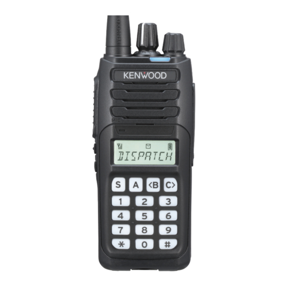
ORIENTATION Buttons and Controls Antenna Speaker Microphone Display Battery pack Keypad Standard Button Model Basic Button Model Full Button Model a Selector Rotate to change the operating channel or zone. b Status indicator Lights during a specified mode, based on dealer programming. (Red, Purple, Blue, Light Blue, Green, Yellow, White) c Power switch/ Volume control Turn clockwise to switch ON the transceiver. -
Page 11: Display
Display Indicator Description Displays the signal strength. The Monitor or Squelch Off function is activated. Blinks when an incoming call matches your Optional Signaling. The Talk Around function is activated. Scan, Priority Scan, or Voting/ Site Roaming is in progress. Blinks when the scan is paused. -
Page 12: Basic Operations
BASIC OPERATIONS SWITCHING POWER ON/ OFF Turn the Power switch/ Volume control clockwise to switch the transceiver power • The Power on text appears if the Power on text has been set. Turn the Power switch/ Volume control counterclockwise to switch the transceiver power OFF. -
Page 13: Transmitting
TRANSMITTING Select the desired zone and channel. Press the button programmed as [Monitor] or [Squelch Off] to check whether or not the channel is free. • If the channel is busy, wait until it becomes free. Press the PTT switch and speak to the microphone. Release the PTT switch to receive. -
Page 14: Making Individual Calls (Nxdn/ Dmr)
Making Individual Calls (NXDN/ DMR) You can select a Unit ID/ name from the list to make a call to those parties on a channel. Press the button programmed as [Individual], [Individual + Short Message] or [Individual + Status] to enter Individual Call Mode. Alternatively, press the button programmed as [Menu] to enter Individual •... -
Page 15: Receiving Group Calls (Nxdn/ Dmr)
Receiving Group Calls (NXDN/ DMR) When you receive a group call on a channel and the received group ID matches the ID set up on your transceiver, you can hear the caller’s voice. Receiving Individual Calls (NXDN/ DMR) When you receive an individual call on a channel, a ringing tone will sound and the display will show the caller’s ID. -
Page 16: Accessible Functions
ACCESSIBLE FUNCTIONS FUNCTION MODE Your transceiver operations vary according to the functions that your dealer has programmed to the transceiver buttons and Selector. Refer to “FUNCTIONS LIST” {p. 18} for the available programmable functions. MENU MODE (LCD Model) Many functions on this transceiver are selected or configured through the Menu instead of physical controls. - Page 17 Press the [ S ] button to view the function list for the selected category. Press [ <B ] and [ C> ] to select a function item. Press the [ A ] button to return to the category list. •...
-
Page 18: Functions List
FUNCTIONS LIST PF Button : Functions that can be programmed to the transceiver buttons Menu : Functions that can be accessed using the transceiver Menu Non-LCD : Non-LCD Model Analog : Channels set up for Analog NXDN : Channels set up for NXDN DMR : Channels set up for DMR ✔... - Page 19 Non- Menu Function Menu Analog NXDN Display Button Digit 1x Down – ✔ ✔ Digit 1x Up – ✔ ✔ Digit 10x Down – ✔ ✔ Digit 10x Up – ✔ ✔ Direct Channel – ✔ ✔ ✔ ✔ ✔ 1 ~ 5 DR 1 SEL Direct Channel 1...
- Page 20 Non- Menu Function Menu Analog NXDN Display Button Lone Worker L-WK ✔ ✔ ✔ ✔ ✔ ✔ Low Transmit LOW PWR ✔ ✔ ✔ ✔ ✔ ✔ Power Maintenance MAINT ✔ ✔ ✔ ✔ ✔ Manual Site Hunt M SITE H ✔...
- Page 21 Non- Menu Function Menu Analog NXDN Display Button RX Auto Gain RX AGC ✔ ✔ ✔ Control SAVE Save Log Data ✔ ✔ ✔ ✔ ✔ ✔ Scan SCAN ✔ ✔ ✔ ✔ ✔ ✔ Scan Delete/Add SCN D/A ✔ ✔...
- Page 22 Non- Menu Function Menu Analog NXDN Display Button Zone Delete/Add ZONE D/A ✔ ✔ ✔ ✔ ✔ ✔ Zone Down – ✔ ✔ ✔ ✔ ✔ Zone Down – ✔ ✔ ✔ ✔ ✔ (Continuous) Zone Select * – ✔ ✔...
-
Page 23: Functions Overview
FUNCTIONS OVERVIEW Following is a brief overview of the functions available on the transceiver accessible using the Menu and/or programmable to the transceiver buttons. • For details on functions that are not included in “FUNCTIONS OVERVIEW” and “FUNCTION DESCRIPTIONS” {p. 66}, please consult your dealer. None [Analog/ NXDN/ DMR] No function has been programmed. - Page 24 Battery Status [Analog/ NXDN/ DMR] Allows you to check the battery power status. PF Button: Press the programmed button, the Battery Status function operates. Menu Mode: Select “BAT STAT” and press the [ S ] button, the Battery Status function operates. Battery status is represented by the number of times the LED indicator flashes red.
- Page 25 Button Lock [Analog/ NXDN/ DMR] Locking the transceiver button operation. This function prevents the incorrect operation of the transceiver by physical contact while carrying the transceiver, such as around the waist. PF Button: Press the programmed button to lock the transceiver buttons. •...
- Page 26 Call Interruption [DMR] Allows a transceiver other than the transmitting transceiver to terminate voice communications by sending a Call Interruption request message. If a transceiver receives a Call Interruption request message on the channel where the transceiver is performing voice communications, the transceiver terminates the voice communications.
- Page 27 Channel Entry [Analog/ NXDN/ DMR] In Channel Entry Mode, channel can be selected by the same operation as List selection. PF Button: Press the programmed button to enter Channel Entry Mode. Press the [ <B ] and [ C> ] buttons to select your desired channel. Press the [ S ] button to confirm the entry.
- Page 28 To enter 3-digit channel number (example: Channel 123): 1 Press the programmed button to enter Channel Entry Mode. Press the [ <B ] and [ C> ] buttons to select “1” Press the [ S ] button. Press the [ <B ] and [ C> ] buttons to select “2”. Press the [ S ] button.
- Page 29 Channel Select [Analog/ NXDN/ DMR] Selector: Turn the Selector to select the channel number. Channel Up/Down [Analog/ NXDN/ DMR] Selector: Turn the Selector to increase/ decrease the channel number. Channel Up/ Channel Down [Analog/ NXDN/ DMR] PF Button: Press the programmed button to increase/ decrease the channel number. Channel Up (Continuous)/ Channel Down (Continuous) [Analog/ NXDN/ DMR] PF Button:...
- Page 30 Digit 1x Up/ Digit 1x Down [Analog] In 5-tone to increment/ decrement the 5-tone selcall code by 1. PF Button: Press the programmed button to increase/ decrease the 5-tone selcall code by 1 with each press. 1st digit code from the right of 5-tone selcall code Digit 10x Up/ Digit 10x Down [Analog]...
- Page 31 Direct Channel 1 ~ 5 Select [Analog/ NXDN/ DMR] Allows you to set the currently selected channel as the Direct Channel 1 ~ 5. Select the channel to be set as Direct Channel. PF Button: Press and hold the programmed button to set the currently selected channel as Direct Channel 1 ~ 5.
- Page 32 Emergency [Analog/ NXDN/ DMR] This is for entering Emergency Mode if the transceiver is in standby mode. If the transceiver is in Emergency mode, it exits the emergency mode. In Emergency Mode, the transceiver repeats transmission and reception at regular intervals. PF Button: Press and hold the programmed button for the time set in hold delay to enter Emergency Mode.
- Page 33 External Speaker [Analog/ NXDN/ DMR] If external speaker connected to the transceiver, select the output of the speaker to the external speaker or internal speaker. PF Button: Press the programmed button to switch the external speaker or internal speaker. Menu Mode: Select “SPEAKER”...
- Page 34 Function [Analog/ NXDN/ DMR] Allows you to access the 2nd function programmed to a button. Programmable buttons can be assigned Main function and 2nd function. PF Button: Press the programmed button to enter 2nd function input wait state. • Beep A (1 beep) sounds. •...
- Page 35 Group + Short Message [Analog/ NXDN/ DMR] Allows you to specify a Group ID to send short messages. PF Button: Press the programmed button to enter Group Call Mode (NXDN/ DMR) or Selcall Mode (FleetSync/ MDC-1200/ 5-tone). Menu Mode: Select “GRP SDM” and press the [ S ] button to enter Group Call Mode (NXDN/ DMR) or Selcall Mode (FleetSync/ MDC-1200/ 5-tone).
- Page 36 High Transmit Power [Analog/ NXDN/ DMR] Turns High Transmit Power On or Off. When using a channel programmed with low or medium power, this allows you to change the output power to high. PF Button: Press the programmed button to change the output power to high. •...
- Page 37 Home Channel Select [Analog/ NXDN/ DMR] Allows you to set the currently selected channel to Home Channel. Select the channel to be set as Home Channel. PF Button: Press and hold the programmed button to set the currently selected channel as the Home Channel. •...
- Page 38 Individual + Short Message [Analog/ NXDN/ DMR] Allows you to specify a Unit ID to send short messages. PF Button: Press the programmed button to enter Individual Call Mode (NXDN/ DMR) or Selcall Mode (FleetSync/ MDC-1200/ 5-tone). Menu Mode: Select “IND SDM” and press the [ S ] button to enter Individual Call Mode (NXDN/ DMR) or Selcall Mode (FleetSync/ MDC-1200/ 5-tone).
- Page 39 Lone Worker [Analog/ NXDN/ DMR] Using Lone Worker function, the transceiver can automatically enter Emergency Mode and notify the base station of the emergency status when the transceiver becomes disabled from operating due to an accident. PF Button: Press the programmed button to change the Lone Worker On. •...
- Page 40 Low Transmit Power [Analog/ NXDN/ DMR] Turns Low Transmit Power On or Off. When using a channel programmed with medium or high power, this allows you to change the output power to low. PF Button: Press the programmed button to change the output power to Low. •...
- Page 41 Maintenance [Analog/ NXDN/ DMR] Allows you to display the signal strength and Bit Error Rate (BER) on the LCD when constructing the system or during maintenance. PF Button: Press the programmed button to enter Maintenance Display Mode. Menu Mode: Select “MAINT” and press the [ S ] button to enter Maintenance Display Mode.
- Page 42 Manual Site Hunt [DMR] Allows you can manually move the Revert Channel to another Channel without waiting for Site Roaming to resume. PF Button: On the Channel of DMR Site Roaming, press the programmed button, the Manual Site Hunt function operates. •...
- Page 43 Menu [Analog/ NXDN/ DMR] PF Button: Press the programmed button to select and perform functions using the transceiver Menu. Microphone Sense [Analog/ NXDN/ DMR] Allows you to change the internal microphone sensitivity. Menu Mode: Select “MIC SENS” and press the [ S ] button. Press the [ <B ] and [ C>...
- Page 44 Microphone Type [NXDN/ DMR] Allows you to configure the type of the external microphone to be connected to the transceiver and enables the optimal conditions of the audio quality. Menu Mode: Select “MIC TYPE” and press the [ S ] button. Press the [ <B ] and [ C>...
- Page 45 Monitor [Analog/ NXDN/ DMR] Allows you to turn the transceiver signaling off, to listen to all calls that are received on the channel. PF Button: Press the programmed button to change the Monitor On. • Beep A (1 beep) sounds. Press this button again to change the Monitor Off.
- Page 46 OST List [Analog] Allows you to enter OST List mode. PF Button: Press and hold the programmed button to enter OST List Mode. Menu Mode: Select “OST LIST” and press the [ S ] button to enter OST List Mode. Press the [ <B ] and [ C>...
- Page 47 Priority-channel Select [Analog/ NXDN/ DMR] A Priority channel must be programmed in order for Priority Scan to function. When using a single Priority channel, the transceiver will automatically change to the Priority channel when a call is received on it, even if a call is being received on a normal channel.
- Page 48 Radio Check (MDC-1200) [Analog] This function is for MDC-1200 Radio Check. Radio Check is a function for checking whether a transceiver is available for calling, such as whether the transceiver is on or whether it is within the reach of radio waves. Menu Mode: Select “RD CHK”...
- Page 49 Radio Uninhibit (MDC-1200) [Analog] This is for MDC-1200 Radio Uninhibit. Radio Uninhibit is a function for reviving a transceiver which has been stunned. Menu Mode: Select “UNINHIB” and press the [ S ] button to enter Radio Uninhibit Mode. Press the [ <B ] and [ C> ] buttons to select the destination ID from the ID List. Press the PTT switch to send Radio Uninhibit command.
- Page 50 Remote Control [NXDN/ DMR] Allows you to remotely control a specified transceiver from the transceiver. In the NXDN and DMR systems, it allows you to operate the transceiver directly, send a remote control message and control the target transceiver. Note: ◆...
- Page 51 Menu Mode: Select “RMT CTRL” and press the [ S ] button to enter Remote Control Mode. Press the [ <B ] and [ C> ] buttons to select Unit ID List. Press the [ S ] button to enter Remote Control Message Selection. Press the [ <B ] and [ C>...
- Page 52 RX Auto Gain Control [NXDN/ DMR] Allows you to set the transceiver to automatically adjust the volume of the receiving sound to a specific level for easy listening. Menu Mode: Select “RX AGC” and press the [ S ] button. Press the [ <B ] and [ C>...
- Page 53 Scan Delete/Add [Analog/ NXDN/ DMR] Allows you to include or omit each channel in the scan sequence. Select your desired channel. PF Button: Press the programmed button to change the Scan Delete/Add status of the channel. Menu Mode: Select “SCN D/A” and press the [ S ] button to activate/ deactivate the Scan of the channel.
- Page 54 Scrambler/Encryption Code [Analog/ NXDN/ DMR] Allows you to change the Scrambler Code/ Encryption Key used in the transmission. PF Button: Press and hold the programmed button to enter Scrambler/ Encryption Code Mode. Menu Mode: Select “SCRENC C” and press the [ S ] button to enter Scrambler/Encryption Code Mode.
- Page 55 Send the GPS Data [Analog/ NXDN/ DMR] Allows you to send your positioning data to the base station when a GPS speaker/ microphone has been installed. • When the power is turned ON and/or the reception condition of the GPS satellite is poor, positioning may take longer to complete.
- Page 56 Speaker Type [NXDN/ DMR] Allows you to configure the type of the external speaker and speaker/ microphone to be connected to the transceiver and enables the optimal conditions of the audio quality. Menu Mode: Select “SPK TYPE” and press the [ S ] button. Press the [ <B ] and [ C>...
- Page 57 Squelch Level [Analog] Allows you to adjust the transceiver squelch level. PF Button: Press the programmed button to enter Squelch Level Adjustment Mode. Menu Mode: Select “SQL LVL” and press the [ S ] button to enter Squelch Level Adjustment Mode. Press the [ <B ] and [ C>...
- Page 58 Stack [Analog/ NXDN/ DMR] Allows you to check the records of received calls and messages received. • The “ ” indicator lights up when all stacked data is already read. • When there is unread data, The “ ” indicator blinks. PF Button: Press the programmed button to enter Stack Mode.
- Page 59 Press the [ <B ] and [ C> ] buttons to select the List. Each time press the [ S ] button to change display type (Message → Caller • ID → Channel No.→ Message→ ). Press the [A] button, delete confirmation is displayed, press the [S] button •...
- Page 60 Surveillance [Analog/ NXDN/ DMR] Allows you to disable the alert tone, backlight and LED functions. The Surveillance function is used when the change of the transceiver status needs to be kept unnoticed, such as while on a Public Safety operation. PF Button: Press the programmed button to activate the Surveillance Mode.
- Page 61 TX Audio Equalizer [NXDN/ DMR] Allows you to set the transmission audio characteristic (Flat, High boost, or Low boost). Menu Mode: Select “TX EQ” and press the [ S ] button. Press the [ <B ] and [ C> ] buttons to select the audio characteristic. Press the [ S ] button to confirm and exit mode.
- Page 62 [Analog/ NXDN/ DMR] Allows you to adjust the VOX Gain level. PF Button: Press the programmed button to enter VOX Gain Level Adjustment Mode. Menu Mode: Select “VOX LVL” and press the [ S ] button to enter VOX Gain Level Adjustment Mode.
- Page 63 Zone Delete/Add [Analog/ NXDN/ DMR] Allows you to include or omit each Zone in the Multi-Zone scan sequence. Select your desired zone. PF Button: Press the programmed button to switch the Zone Delete/Add status of the channel. Menu Mode: Select “ZONE D/A” and press the [ S ] button to switch the Zone Delete/Add status of the channel.
-
Page 64: Keypad Operation
KEYPAD OPERATION The keypad operating method can be selected according to the purpose. Even pressing the [ 0 ] ~ [ 9 ], [ ], [ # ] button, and None button-entry Error Tone will sound and no operation will be performed. - Page 65 This function allows you to send DTMF by pressing Keypad without PTT switch. • If DTMF Manual Dialing is Enabled, the DTMF Code is sent by pressing the [ 0 ] ~ [ 9 ], [ ], [ # ] button. Keypad Auto PTT Press the [ 0 ] ~ [ 9 ], [ ], [ # ] button, send the DTMF...
-
Page 66: Function Descriptions
FUNCTION DESCRIPTIONS For details on functions that are not included in “FUNCTIONS OVERVIEW” {p. 23} and “FUNCTION DESCRIPTIONS”, please consult your dealer. TRANSCEIVER PASSWORD LCD Model If the transceiver is password protected, “PASSWORD” will appear on the display when the power is turned on. To unlock the transceiver, enter the correct password. - Page 67 Non-LCD Model If your transceiver is password protected, the LED will light blue when you turn the transceiver ON. Enter the password (up to 6 digits) using the following procedure. Set the Selector to position “1”. Press the Side 1 or Side 2 button to enter the first digit. The Side 1 button increases the digit value and the Side 2 button •...
- Page 68 SCAN Scan is useful for monitoring signals on the transceiver channels. While scanning, the transceiver checks for a signal on each channel and only stops on a channel if a signal is present. To begin scanning, press the button programmed as [Scan]. •...
- Page 69 SCAN REVERT The Scan Revert channel is the channel selected when you press the PTT switch to transmit during scan. Your dealer can program one of the following Scan Revert channels: Selected: The last channel selected is assigned as the new revert channel. •...
- Page 70 DTMF (DUAL TONE MULTI FREQUENCY) CALLS Note: ◆ Manual Dialing and Keypad Auto PTT are available only on full button model. MAKING A DTMF CALL Manual Dialing Press and hold the PTT switch. Enter the desired digits using the keypad. •...
- Page 71 EMERGENCY CALLS If your transceiver has been programmed with the Emergency function, you can make emergency calls. Press and hold the button programmed as [Emergency]. • Depending on the delay time programmed into your transceiver, the length of time you must hold the Emergency button will vary. •...
- Page 72 SCRAMBLER (ANALOG)/ ENCRYPTION (NXDN/ DMR) Note: ◆ The following types of encryption are available depending on the protocol used. NXDN : Bit scrambling (built-in encryption function) DMR : Bit scrambling (built-in encryption function) and Enhanced Encryption ◆ The Enhanced Encryption is a software option. Ask your dealer for details concerning the Enhanced Encryption settings.
- Page 73 SELECTING THE ENCRYPTION KEY Press the button programmed as [Scrambler/Encryption Code] to enter Scrambler/Encryption Code Mode. Alternatively, press the button programmed as [Menu] to enter Scrambler/ • Encryption Code Mode using the Menu Mode. 2 Select the new Encryption key using the [ <B ] and [ C> ] buttons. •...
- Page 74 SIGNALING QUIET TALK (QT)/ DIGITAL QUIET TALK (DQT) [ANALOG] Your dealer may have programmed QT or DQT signaling on your transceiver channels. A QT tone/ DQT code is a sub-audible tone/ code which allows you to ignore (not hear) calls from other parties who are using the same channel. When a channel is set up with a QT tone or DQT code, squelch will only open when a call containing a matching tone or code is received.
- Page 75 OPTIONAL SIGNALING Your dealer may also program several types of optional signaling for your transceiver channels. 5-tone Signaling [Analog] Refer to “5-TONE SIGNALING” {p. 79}. DTMF Signaling [Analog] DTMF Signaling opens the squelch only when the transceiver receives a call containing a matching DTMF code.
- Page 76 FleetSync: ALPHANUMERIC 2-WAY PAGING FUNCTION FleetSync is an Alphanumeric 2-way Paging Function, and is a protocol owned by JVCKENWOOD Corporation. FleetSync enables a variety of paging functions on your transceiver, some of which depend on dealer programming. Note: ◆ This function is available only in analog operation. SELCALL (SELECTIVE CALLING) A Selcall is a voice call to a station or group of stations.
- Page 77 Identification Codes An ID code is a combination of a 3-digit Fleet number and a 4-digit ID number. Each transceiver has its own ID. • Enter a Fleet number (100 ~ 349) to make a fleet call. • Enter an ID number (1000 ~ 4999) to make an individual call in your fleet. •...
- Page 78 SHORT MESSAGES This transceiver can receive short data messages which contain a maximum of 48 characters. GPS REPORT GPS data can be manually transmitted by pressing the button programmed as [Send the GPS Data], or by accessing the Menu. If set up by your dealer, GPS data may be automatically transmitted at a preset time interval.
- Page 79 5-TONE SIGNALING 5-tone Signaling is enabled or disabled by your dealer. This function opens the squelch only when the transceiver receives the 5 tones programmed in your transceiver. Transceivers that do not transmit the correct tones will not be heard. SELCALL (SELECTIVE CALLING) A Selcall is a voice call to a station or group of stations.
- Page 80 STATUS MESSAGE You can send and receive Status messages which may be decided in your talk group. Messages can contain up to 8 alphanumeric characters. A maximum of 32 received messages can be stored in the stack memory of your transceiver.
- Page 81 VOICE OPERATED TRANSMISSION (VOX) VOX (VOX/ Semi-VOX) operation allows you to transmit hands-free. This feature can be activated or deactivated by your dealer. To operate VOX, you must use an optional headset. VOX Type VOX: When the voice level to the microphone is higher than the reference level (VOX Gain Level), the transceiver automatically starts transmission.
- Page 82 Semi-VOX Operation Connect a headset to the transceiver. • The VOX function does not activate when a headset is not connected to the accessory terminal of the transceiver. Press the button programmed as [VOX Function]. Alternatively, you can press the button programmed as [Menu] to enter •...
- Page 83 BACKGROUND OPERATIONS TIME-OUT TIMER (TOT) The Time-out Timer is used to prevent any caller from using a channel for an extended period of time. If you continuously transmit for a period of time that exceeds the programmed time, the transceiver will stop transmitting and an alert tone will sound. To stop the tone, release the PTT switch.
- Page 84 VOICE ANNOUNCEMENT An audio voice will be announced as below by dealer setting. • When changing the zone and/or channel, the new zone and channel number are announced. • When changing the function setting, the new setting is announced. - Scrambler/Encryption - VOX Function - Home Channel - Button Lock...
- Page 85 BUSY CHANNEL LOCKOUT (BCL) If BCL is set up by your dealer, you will be unable to transmit on the channel if it is already in use. Under these circumstances, use a different channel or wait until the channel becomes free. However, if BCL Override has also been programmed, you can transmit over the current signal: Press and hold the PTT switch.
- Page 86 NX-1200-E NX-1300-E NX-1200-E2 NX-1300-E2 NX-1200-E3 NX-1300-E3 136.000 - 174.000 MHz 400.000 - 470.000 MHz Frequency Range (TX/RX) Maximum Output Power –30°C - +60°C Operating Temperature Range The device complies with RF exposure requirement. © 2021...