
Related Manuals for Siemens RDF302/VB


Summary of Contents for Siemens RDF302/VB
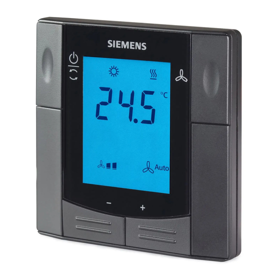
- Page 1 RDF302, RDF302.B RDF302/VB Flush-mounted room thermostats with RS485 Modbus communications RDF302, RDF302/VB, RDF302.B Basic documentation Edition 1.6 CE1P3079en Smart Infrastructure 2022-06-17...
-
Page 2: Table Of Contents
Fan control ..................34 Multifunctional input, digital input............37 3.10 Handling faults ..................39 3.11 Modbus RTU mode ................40 3.11.1 Fault function on Modbus ..............40 3.12 Communication objects................ 41 2 / 62 Siemens RDF302 Basic documentation CE1P3079en Smart Infrastructure Contents 2022-06-17... - Page 3 Operation..................... 53 Disposal ....................54 Connection ..................55 Connection terminals ................55 Connection diagrams ................56 Mechanical design ................57 General ....................57 Dimensions ..................58 Technical data ..................59 3/62 Siemens RDF302 Basic documentation CE1P3079en Smart Infrastructure Contents 2022-06-17...
-
Page 4: About This Document
Pages 2022-06-17 Add one more value of P06 3.12.2 3.13.3 2020-12-01 Update function code description 3.12.2 45-49 2020-02-21 Add product RDF302/VB related information 3.7.1 3.11 3.12.1 2018-12-04 Add product RDF302.B related information 1.1, 1.2 1.4, 1.5 2.1, 2.2 3.2.1 13-14 3.6.4... -
Page 5: Reference Documents
Before you start 1.3.1 Copyright This document may be duplicated and distributed only with the express permission of Siemens, and may be passed only to authorized persons or companies with the required technical knowledge. 1.3.2 Quality assurance This document was prepared with great care. -
Page 6: Target Audience, Prerequisites
Target audience, prerequisites Product & sales managers, distributors, re-sellers & OEM customers who use RDF302, RDF302/VB and RDF302.B room thermostats in the RS485 Modbus RTU network. Since Modbus protocol has been well known for years in the industry, this document will explain the operations related to RDF302, RDF302/VB and RDF302.B Modbus units. -
Page 7: Summary
Modbus Room thermostat S55770-T416 Basic Modbus room thermostat RDF302.B S55770-T428 Modbus Room thermostat RDF302/VB For input and output difference between RDF302, RDF302/VB and RDF302.B, see Connection terminals. Order valve actuators separately. Functions Fan coil units via ON/OFF outputs: • 2-pipe system * •... -
Page 8: Integration Via Modbus
• RS 485 Modbus (terminals +, - and REF) for communication with Modbus compatible devices Integration via Modbus The RDF302, RDF302/VB and RDF302.B are communicative thermostat with Modbus open protocol on RTU (Remote Terminal Unit) mode enabling easy integration into BACS via RS-485. -
Page 9: Equipment Combinations
Changeover mounting kit ARG86.3 N3009 (50 pcs / package) Plastic mounting spacer for flush ARG70.3 N3009 mount thermostats to increase the headroom in the conduit box by 10 mm 9 / 62 Siemens RDF302 Basic documentation CE1P3079en Smart Infrastructure 2022-06-17... -
Page 10: Functions
P07 = 3 or 4. The display format is either in 12- or in 24-hour format. Time of day The information can be received from a master device in the Modbus network. 10 / 62 Siemens RDF302 Basic documentation CE1P3079en Smart Infrastructure... -
Page 11: Operating Modes
– protected against overheating (factory setting OFF, can be enabled or changed via P66) No other operating mode can be selected locally if Protection mode is commanded via Modbus. is displayed. 11 / 62 Siemens RDF302 Basic documentation CE1P3079en Smart Infrastructure 2022-06-17... -
Page 12: Different Ways To Influence The Operating Mode
• Suited for hotel guest rooms or commercial buildings. • Switching manually between 3 modes → → • Suited for homes and rooms where manual switching to Economy mode is desired 12 / 62 Siemens RDF302 Basic documentation CE1P3079en Smart Infrastructure 2022-06-17... -
Page 13: Room Temperature Setpoint
4-pipe heating AND cooling P09 < P10 Cooling setpoint adjustable 18…25 ° C Cooling setpoint adjustable 18…25 ° C Heating setpoint adjustable 18…25 ° C Heating setpoint adjustable 18…25 ° C 13 / 62 Siemens RDF302 Basic documentation CE1P3079en Smart Infrastructure 2022-06-17... -
Page 14: Setting And Adjusting Setpoints
– a Modbus commissioning tool Comfort setpoint – a Modbus master unit The thermostat stores the setpoints – in EEPROM in the form of parameters The table below shows the interrelations: 14 / 62 Siemens RDF302 Basic documentation CE1P3079en Smart Infrastructure 2022-06-17... - Page 15 Protection setpoint is OFF, then minimum 5 ° C and maximum 40 ° C are used • The resulting setpoints for cooling and heating of the same operating mode have a minimum distance of 0.5 K between them 15 / 62 Siemens RDF302 Basic documentation CE1P3079en Smart Infrastructure 2022-06-17...
-
Page 16: Applications Overview
3.4.1 “Applications for fan coil systems” • section 3.4.2 “Applications for universal systems” • section 3.4.3 “Applications for heat pump systems” • section 3.6.5 “Universal applications” • section 3.6.6 “Compressor applications”. 16 / 62 Siemens RDF302 Basic documentation CE1P3079en Smart Infrastructure 2022-06-17... - Page 17 B2 Changeover sensor (optional) E1 Electric heater M1 3- or 1-speed fan RDF302.B does not have inputs X1 and X2, so sensor B1 and B2 are not included in RDF302.B application. 17 / 62 Siemens RDF302 Basic documentation CE1P3079en Smart Infrastructure 2022-06-17...
-
Page 18: Applications For Universal Systems
B2 Changeover sensor (optional) E1 Electric heater D3 Dewpoint sensor RDF302.B does not have inputs X1 and X2, so sensor B1 and B2 are not included in RDF302.B application. 18 / 62 Siemens RDF302 Basic documentation CE1P3079en Smart Infrastructure 2022-06-17... - Page 19 Terminal Y21: for cooling (H &C) E1 Electric heater D3 Dewpoint sensor RDF302.B does not have inputs X1 and X2, so sensor B1 and B2 are not included in RDF302.B application. 19 / 62 Siemens RDF302 Basic documentation CE1P3079en Smart Infrastructure 2022-06-17...
-
Page 20: Additional Functions
• If manual heating / cooling changeover is commissioned (P01 = 2), then heating / cooling mode cannot be changed via changeover sensor / switch; it will remain in the last mode as selected locally via button. 20 / 62 Siemens RDF302 Basic documentation CE1P3079en Smart Infrastructure... - Page 21 Up to 26 ° C for long-time presence, up to 28 ° C for short-time presence. Bath rooms: Up to 28 ° C for long-time presence, up to 30 ° C for short-time presence. 21 / 62 Siemens RDF302 Basic documentation CE1P3079en Smart Infrastructure...
- Page 22 A = Lock all buttons B = Lock operating mode button only C = Lock fan button only D = Lock temperature adjusting buttons (+ & -) only. E = Unlock 22 / 62 Siemens RDF302 Basic documentation CE1P3079en Smart Infrastructure 2022-06-17...
-
Page 23: Control Sequences
– 4-pipe automatic changeover (P01 = 3) means swapping the control outputs according to a heating / cooling sensor or remote switch ("main and secondary" application), see section 3.6.4 For the relation between setpoints and sequences, see section 3.6.7. 23 / 62 Siemens RDF302 Basic documentation CE1P3079en Smart Infrastructure 2022-06-17... -
Page 24: 2-Pipe Fan Coil Unit
Control command “Valve” Note: The diagrams only show the PI thermostat’s proportional part. Setting the sequence and the control outputs Refer to sections 3.4 "Applications", 3.6.1 "Sequences", and 3.7 "Outputs". 24 / 62 Siemens RDF302 Basic documentation CE1P3079en Smart Infrastructure 2022-06-17... -
Page 25: 2-Pipe Fan Coil Unit With Electric Heater
If “Enable electric heater” input is used via Modbus, then the function must not be assigned to a local input X1 or X2. Caution An electric heater must always be protected by a safety limit thermostat! 25 / 62 Siemens RDF302 Basic documentation CE1P3079en Smart Infrastructure 2022-06-17... - Page 26 Setpoint differential (P34) Note: The diagrams only show the PI thermostat’s proportional part. Setting the sequence and the control outputs Refer to sections 3.4 "Applications", 3.6.1 "Sequences", and 3.7 "Outputs". 26 / 62 Siemens RDF302 Basic documentation CE1P3079en Smart Infrastructure 2022-06-17...
-
Page 27: 4-Pipe Fan Coil Unit
• The thermostat assumes winter operation when B2 > P37 (factory setting 28 ° C) • The thermostat assumes summer operation when B2 < P36 (factory setting 16 ° C) • RDF302.B does not have inputs X1 and X2. 27 / 62 Siemens RDF302 Basic documentation CE1P3079en Smart Infrastructure... - Page 28 Dead zone (P33) Note: The diagrams only show the PI thermostat’s proportional part. Setting the sequence and the control outputs Refer to sections 3.4 "Applications", 3.6.1 "Sequences", and 3.7 "Outputs". 28 / 62 Siemens RDF302 Basic documentation CE1P3079en Smart Infrastructure 2022-06-17...
-
Page 29: Chilled / Heated Ceiling And Radiator Applications
• Minimum ON/OFF time: P48 / P49 Notes: • Fan operation: P52 (0 = disabled, 1 = enabled) • Fan speed: P53 (1 = 1-speed, 2 = 3-speed) 29 / 62 Siemens RDF302 Basic documentation CE1P3079en Smart Infrastructure 2022-06-17... -
Page 30: Setpoints And Sequences
W = setpoint in Comfort mode = setpoint heating in Economy or Protection mode HeatEco/Prot = setpoint cooling in Economy or Protection mode CoolEco/Prot YR = radiator sequence E1 = electric heater sequence 30 / 62 Siemens RDF302 Basic documentation CE1P3079en Smart Infrastructure 2022-06-17... - Page 31 1) Manual changeover, P01 = 2 W = setpoint in Comfort mode = heating setpoint for Economy or Protection mode HeatEco/Prot = cooling setpoint for Economy or Protection mode CoolEco/Prot 31 / 62 Siemens RDF302 Basic documentation CE1P3079en Smart Infrastructure 2022-06-17...
-
Page 32: Control Outputs
Different control output signals are available. They need to be defined during outputs commissioning (see below). Control output → 2-position 3-position Product no.↓ RDF302, RDF302/VB, Y11, Y21 Y11, Y21 *) RDF302.B (2 x SPST) (1 x *) Only on 2-pipe application... -
Page 33: Control Outputs Configuration (Setting Via Dip Switches Or Modbus Commissioning Tool)
4-pipe and 2-pipe with electric heater, only have On/Off type of outputs. The application and control output can be changed between On/Off and 3-position Plant type via Modbus. 33 / 62 Siemens RDF302 Basic documentation CE1P3079en Smart Infrastructure 2022-06-17... -
Page 34: Fan Control
Control command “Valve” Switching differential “Heating” Switching differential “Cooling” Dead zone Switching range for fan “Heating” Switching range for fan “Cooling” SDH/SDC >4.5 Look-up table with /XpC ON/OFF control 34 / 62 Siemens RDF302 Basic documentation CE1P3079en Smart Infrastructure 2022-06-17... - Page 35 When the fan starts from standstill, it starts at speed 3 for 1 second to ensure safe fan motor start by overcoming inertia and friction (selected via parameter P58). 1 sec 35 / 62 Siemens RDF302 Basic documentation CE1P3079en Smart Infrastructure...
- Page 36 The “Clean fan filter reminder” is reset when the operating mode is manually set to Protection and back. The ‘Clean fan filter reminder’ and error information (see 3.11.1) can be obtained Fault information via Modbus object: Fault information 36 / 62 Siemens RDF302 Basic documentation CE1P3079en Smart Infrastructure 2022-06-17...
-
Page 37: Multifunctional Input, Digital Input
X1, X2. See also section 3.5. Diagnostic value 0 ˚C is displayed for closed contact / 100 ˚C for open contact, if a switch is connected. 37 / 62 Siemens RDF302 Basic documentation CE1P3079en Smart Infrastructure 2022-06-17... - Page 38 Sensor input to monitor the state of an external (Temperature) sensor (e.g. QAH11.1) via Modbus. • Operational action can be changed between normally open (NO) and normally closed (NC) via parameter P39, P41 38 / 62 Siemens RDF302 Basic documentation CE1P3079en Smart Infrastructure 2022-06-17...
-
Page 39: Handling Faults
For all other cases, no output is activated. The thermostat resumes Comfort mode after the temperature returns to within the measuring range. For fault status messages on the Modbus, see section 3.11.1. Fault information 39 / 62 Siemens RDF302 Basic documentation CE1P3079en Smart Infrastructure 2022-06-17... -
Page 40: Modbus Rtu Mode
3.11 Modbus RTU mode The RDF302, RDF302/VB and RDF302.B thermostats support communication protocol (Modbus RTU mode) as per the Modbus specification (refer to: http://www.modbus.org). Device address The device address range is from 1 to 247. The device address can be changed via parameter P81. (factory setting = 1) Baud rate The available baud rates are 4800 bps, 9600 bps, 19200bps and 38400 bps. -
Page 41: Communication Objects
P01 must be set to 3, the manual heating/cooling changeover Either using local input, X1/X2 input, or Modbus command Dip switch position 1 to 3 must be set to OFF-OFF-OFF Not applicable to RDF302.B 41 / 62 Siemens RDF302 Basic documentation CE1P3079en Smart Infrastructure 2022-06-17... -
Page 42: Description Of Communication Objects
Room operating 0101 0x03 0x06 Comfort 1=Comfort, 3=Economy, mode: 4=Protection, Preselection 0 = Auto Fan command 0102 0x03 0x06 33 = Low Fan value 66 = Mid Fan 42 / 62 Siemens RDF302 Basic documentation CE1P3079en Smart Infrastructure 2022-06-17... - Page 43 2:= Comf - Eco - Prot ° C := Degrees Celsius 0004 0x03 0x06 ° C (0) ° F := Degrees Fahrenheit – 3 ... 3 K 0005 0x03 0x06 43 / 62 Siemens RDF302 Basic documentation CE1P3079en Smart Infrastructure 2022-06-17...
- Page 44 1:= Normally closed / Close 0:= Normally open / Open 0041 0x03 0x06 0 (N.O.) 1:= Normally closed / Close 20…300 sec 0044 0x03 0x06 150 s 0.0~5.0 0182 0x03 0x06 44 / 62 Siemens RDF302 Basic documentation CE1P3079en Smart Infrastructure 2022-06-17...
- Page 45 PROTECTION and AUTO TIMER symbols ** RDF302.B does not have inputs X1 and X2. Parameters related x1 and X2 input functions are not applicable to RDF302.B. 45 / 62 Siemens RDF302 Basic documentation CE1P3079en Smart Infrastructure 2022-06-17...
- Page 46 0 : Time = UT+X {0,1} Standard 1 : Time = UT+X+1 Summer Time 0 : clock without ext. sync signal {0,1} Quality of 1 : clock with ext. sync signal Clock 46 / 62 Siemens RDF302 Basic documentation CE1P3079en Smart Infrastructure 2022-06-17...
-
Page 47: Control Parameters
3.13.2 Parameter setting / download via Modbus communication tool Control parameters can be adjusted via Modbus either by local HMI or Modbus commissioning tools. Please refer to section 4.2 for commissioning. 47 / 62 Siemens RDF302 Basic documentation CE1P3079en Smart Infrastructure 2022-06-17... -
Page 48: Parameters Of The "Service Level
0 (Disabled) 2 = Manual lock Note: Parameter P13 is only displayed for application "2-pipe with electric heater". All temperature settings are in increments of 0.5 ° C. 48 / 62 Siemens RDF302 Basic documentation CE1P3079en Smart Infrastructure 2022-06-17... -
Page 49: Parameters Of The "Expert Level With Diagnostics And Test
ON: Enabled Fan start kick OFF: Disabled Fan minimum on time 2 min 1...6 min Periodic fan kick Comfort 0…89 min, OFF(90) Periodic fan kick Eco 0…359 min, OFF(360) 49 / 62 Siemens RDF302 Basic documentation CE1P3079en Smart Infrastructure 2022-06-17... - Page 50 “---”. Press buttons + and – simultaneously to escape. actuator's running direction Note: Parameters d05 will only appear when the application (DIP switch) set to 2 pipe 3 position. 50 / 62 Siemens RDF302 Basic documentation CE1P3079en Smart Infrastructure 2022-06-17...
-
Page 51: Handling
• Isolate the cables of Modbus communication input +, - and REF for 230 V. • No metal conduits. • No cables provided with a metal shield. • Disconnect from supply before opening the cover. 51 / 62 Siemens RDF302 Basic documentation CE1P3079en Smart Infrastructure 2022-06-17... -
Page 52: Commissioning
To do this, change parameter P05 • We recommend to review the setpoints and setpoint ranges (parameters Setpoint and range limitation P08…P12) and change them as needed to achieve maximum comfort and save energy 52 / 62 Siemens RDF302 Basic documentation CE1P3079en Smart Infrastructure 2022-06-17... -
Page 53: Operation
Operation See also Operating Instructions B3171 [2] enclosed with the thermostat. Layout RDF302, RDF302/VB, RDF302.B 1 Operating mode selector 2 Button to change fan operation 3 Buttons to adjust setpoints and control parameters Button operation User action Effect, description Normal operation... -
Page 54: Disposal
European Directive and may not be disposed of as domestic garbage. • Dispose of the device through channels provided for this purpose. • Comply with all local and currently applicable laws and regulations. 54 / 62 Siemens RDF302 Basic documentation CE1P3079en Smart Infrastructure 2022-06-17... -
Page 55: Connection
(function can be selected via parameter P38/P40). Measuring neutral for sensor and switch RS485 Modbus connection RS485 Modbus connection RS485 signal/common ground (Differential common) RDF302.B does not have inputs X1, X2 and M. 55 / 62 Siemens RDF302 Basic documentation CE1P3079en Smart Infrastructure 2022-06-17... -
Page 56: Connection Diagrams
Heater 4-pipe / Heating and radiator V1 = Heating V2 = Cooling 1-stage compressor C1 = Heating and / or C2 = Cooling 1-stage compressor and electric heater 56 / 62 Siemens RDF302 Basic documentation CE1P3079en Smart Infrastructure 2022-06-17... -
Page 57: Mechanical Design
The base fits on a square conduit box with 60.3 mm fixing centers. Slide the front panel in the mounting base and snap on. Operation and settings RDF302, RDF302/VB, RDF302.B 1. Operating mode selector 2. Change fan operation 3. Adjust setpoints and control parameters For operation, refer to section 4.3. -
Page 58: Dimensions
Dimensions Dimensions in mm 58 / 62 Siemens RDF302 Basic documentation CE1P3079en Smart Infrastructure 2022-06-17... -
Page 59: Technical Data
1.5 mm and length < 1200 m Bus current Max. 50 mA Modbus topology: See Modbus manual (MODBUS over serial line specification and implementation guide from http://www.modbus.org 59 / 62 Siemens RDF302 Basic documentation CE1P3079en Smart Infrastructure 2022-06-17... - Page 60 RAL 9004 black Weight without / with packaging 0.174 kg/0.261 kg The documents can be downloaded from http://siemens.com/bt/download. RDF302.B does not have inputs X1 and X2. Parameters related to X1 and X2 input functions are not applicable to RDF302.B. No condensation is allowed.
- Page 61 Fault ..............38 Standby / Protection mode........11 Fault on KNX ............40 Switching differential ..........10 Fault, handling ............ 39 Synchronization ...........33 Floor cooling ............21 Floor heating............21 61 / 62 Siemens RDF302 Basic documentation CE1P3079en Building Technologies Index 2022-06-17...
- Page 62 Window contact ..........13 Temporary setpoint ..........13 Window state..........11, 38 Universal applications ......... 16 Issued by © Siemens Switzerland Ltd, 2011 (-2022) Siemens Switzerland Ltd Technical specifications and availability subject to change without notice. Smart Infrastructure Global Headquarters Theilerstrasse 1a CH-6300 Zug Tel.