HP ProCurve 2124 Install Manual
Hp procurve 2124: install guide
Hide thumbs
Also See for ProCurve 2124:
- Product overview (4 pages) ,
- Supplementary manual (2 pages) ,
- Brochure & specs (5 pages)
Table of Contents
Advertisement
Advertisement
Table of Contents

Related Manuals for HP ProCurve 2124


Summary of Contents for HP ProCurve 2124
- Page 1 2124 www.hp.com/go/hpprocurve...
- Page 3 HP Procurve Switch 2124 Installation Guide...
- Page 4 A copy of the specific warranty terms applicable to your Hewlett-Packard products and replacement parts can be obtained from your HP Sales and Service Office or authorized dealer. Safety Before installing and operating this product, please read the “Installation Precautions”...
-
Page 5: Table Of Contents
Switch Operation Overview ........1-6... - Page 6 Testing End-to-End Network Communications ....3-6 HP Customer Support Services ....... . . 3-6 A Specifications Physical .
-
Page 7: Introducing The Hp Procurve Switch 2124
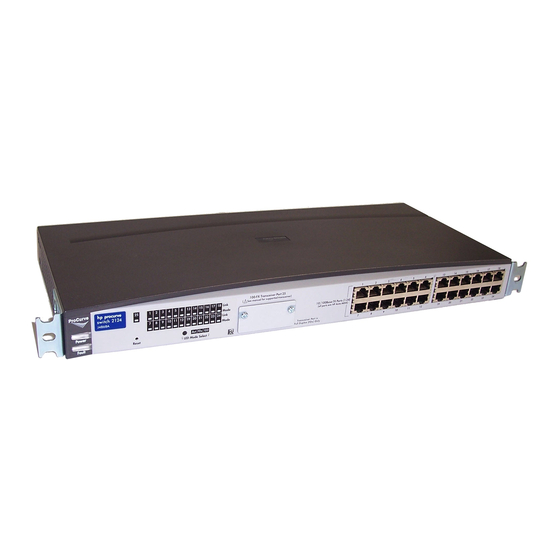
Introducing the HP Procurve Switch 2124 The HP Procurve Switch 2124 is a multiport switch that can be used to build high-performance switched workgroup networks. This switch is a store-and- forward device that offers low latency for high-speed networking. HP Procurve Switch 2124 (HP J4868A) Throughout this manual, this switch will be abbreviated as the Switch 2124. -
Page 8: Front Of The Switch
LEDs Network Ports 24 auto-sensing 10/100Base-TX RJ-45 ports All these ports have the “HP Auto-MDIX” feature, which means that you can use either straight-through or crossover twisted-pair cables to connect any network devices to the switch. One transceiver slot for installing the HP 100-FX SC Transceiver... -
Page 9: Leds
On briefly after the switch is powered on or reset, at the beginning of switch self test. If on for a prolonged time, the switch has a hardware failure, or has failed its self test. See chapter 3, “Troubleshooting” for more information. -
Page 10: Led Mode Select Button And Indicator Leds
To optimize the amount of information that can be displayed for each of the switch ports without overwhelming you with LEDs, the Switch 2124 uses a Mode LED for each port. The operation of this LED is controlled by the LED Mode Select button, and the current setting is indicated by the Mode indicator LEDs near the button. -
Page 11: Back Of The Switch
AC power connector Power Connector The Switch 2124 does not have a power switch; it is powered on when connected to an active AC power source. The switch automatically adjusts to any voltage between 100--240 volts and either 50 or 60 Hz. There are no voltage... -
Page 12: Features
The features of the Switch 2124 include: 24 auto-sensing 10/100Base-TX RJ-45 ports with “HP Auto-MDIX” a slot for installing an HP 100-FX SC Transceiver (HP J4853A) plug-and-play networking — all ports are enabled — just connect the network cables to active network devices and your switched network is operational “HP Auto-MDIX”... - Page 13 Switch 2124 cannot know whether to forward or filter out the packet. In this case, it sends the packet to all the other switch ports. This is referred to as “flooding”. When the destination device receives the packet, it replies, and the switch learns the new address from the reply packet.
-
Page 15: Installing The Switch 2124
Installing the Switch 2124 The HP Switch 2124 is easy to install. It comes with an accessory kit that includes the brackets for mounting the switch in a standard 19-inch telco rack or an equipment cabinet, or on a wall, and with rubber feet that can be attached so the switch can be securely located on a horizontal surface. -
Page 16: Installation Procedures
Please see page 2-3 for some installation precautions. (Optional) Install the transceiver. The Switch 2124 has a slot for installing an HP 100-FX SC Transceiver (HP J4853A). Depending on where you will locate the Switch 2124, it may be easier to install the transceiver first. -
Page 17: Installation Precautions
Installation Precautions: Follow these precautions when installing your HP Switch 2124. W a r n i n g The rack or cabinet should be adequately secured to prevent it from becoming unstable and/or falling over. Devices installed in a rack or cabinet should be mounted as low as possible, with the heaviest device at the bottom and progressively lighter devices installed above. -
Page 18: Prepare The Installation Site
Installation Location - Before installing the switch, plan its location and orientation relative to other devices and equipment: • At the front of the switch, leave at least 7.6 cm (3 inches) of space for the twisted-pair and fiber-optic cabling. •... -
Page 19: Install An Optional Transceiver
2. Install An Optional Transceiver Install an optional HP 100-FX SC Transceiver into the transceiver slot as shown in the illustration below, or by following the instructions in the manual that comes with the transceiver. The slot cover can be removed with either a flat-bladed or Torx T-10 screw- driver. -
Page 20: Verify The Switch Operates Correctly
N o t e The Switch 2124 does not have a power switch. It is powered on when the power cord is connected to the switch and to a power source. For safety, the power outlet should be located near the switch installation. - Page 21 Power and Fault LEDs When the switch is powered on, it performs its diagnostic self test. The self test takes approximately 3 seconds to complete. LED Behavior: During the self test: • All the switch and port LEDs are on.
-
Page 22: Mount The Switch
4. Mount the Switch After a transceiver has been installed and you have verified that the switch passes its self test, you are ready to mount the switch in a stable location. The Switch 2124 can be mounted in these ways:... - Page 23 (0.5-inch) pair on both sides of the rack Place the switch in the rack and lower it so the notches in the bottom of the bracket slide onto the screws, then tighten these screws. lower switch with mounting...
-
Page 24: Wall Mounting
You can mount the switch on a wall as shown in the illustrations below. C a u t i o n The switch should be mounted only to a wall or wood surface that is at least 1/2-inch plywood or its equivalent. - Page 25 Installing the Switch 2124 Installation Procedures Attach the switch to the wall or wood surface with 5/8-inch number 12 wood screws (not included). For “Bookshelf” Wall Mounting For “Flat” Wall Mounting 5/8-inch wood screw 5/8-inch wood screws second 5/8-inch wood screw (hidden)
-
Page 26: Connect The Switch To A Power Source
Place the switch on a table or other horizontal surface. The switch comes with rubber feet in the accessory kit that can be used to help keep the switch from sliding on the surface. Attach the rubber feet to the four corners on the bottom of the switch within the embossed angled lines. -
Page 27: Connect The Network Cables
Connect the network cables, described under “Cabling Infrastructure” (page 2-4), from the network devices or your patch panels to the fixed RJ-45 ports on the switch, or to an HP 100-FX SC Transceiver, if one is installed in the switch. -
Page 28: Example Network Topologies
Notice that the end node devices are connected to the switch by “straight-through” or “crossover” twisted-pair cables. Either cable type can be used because of the “HP Auto-MDIX” feature on the Switch 2124. N o t e The HP 100-FX SC Transceiver, when installed in a Switch 2124, operates only at 100 Mbps and full duplex. -
Page 29: As A Segment Switch
The switch, in turn, is connected to a network backbone through fiber-optic cabling connected to an HP 100-FX SC Transceiver installed in the switch. Now, all the devices on these network segments can access other network resources that are connected elsewhere on the network backbone. -
Page 30: Connecting To A Backbone Switch
The simpler desktop and segment networks shown in the previous two examples can easily be combined and expanded. For example, you could use an HP Procurve Switch 8000M to interconnect each of your smaller switched workgroups to form a larger switched network. All the devices in this network can communicate with each other. -
Page 31: Troubleshooting
(all hubs are configured this way, for example). Connecting the 100Base-FX transceiver port to other devices. An HP 100-FX SC Transceiver installed in the Switch 2124 operates only at 100 Mbps and full duplex. When connecting this port to any other device,... - Page 32 For more information on possible network problems and their solutions, refer to the technical note “Troubleshooting LAN Performance and Intermittent Connectivity Problems”, which can be found on the HP Procurve web site, http://www.hp.com/go/hpprocurve in the Information Library section.
-
Page 33: Diagnosing With The Leds
If the power source and power cord are OK and this condition persists, the switch power supply may have failed. Call your HP-authorized LAN dealer, or use the electronic support services from HP to get assistance. See the Customer Support/ Warranty booklet for more information. - Page 34 See the Customer Support/Warranty booklet for more informa- tion. ™ An unsupported The Switch 2124 supports installation of only the HP J4853A 100-FX SC Transceiver. transceiver has If you have installed any other transceiver, the Port 25 Link LED will blink been installed in simultaneously with the switch Fault LED.
-
Page 35: Hardware Diagnostic Tests
Switch 2124 must be compatible with the appropriate stan- dards. To verify that your cable is compatible with these standards, use a qualified cable test device. HP also offers a wire testing service. Contact your HP-authorized LAN dealer or your local HP sales office for more information. Troubleshooting... -
Page 36: Testing End-To-End Network Communications
The HP Procurve web site, http://www.hp.com/go/hpprocurve also provides up-to-date support information. Additionally, your HP-authorized network reseller can provide you with assis- tance, both with services that they offer and with services offered by HP. -
Page 37: Physical
Specifications Physical Width: Depth: Height: Weight : Electrical The switch automatically adjusts to any voltage between 100-240 volts and either 50 or 60 Hz. AC voltage: Maximum current: Frequency range: Environmental Temperature: Relative humidity: (non-condensing) Maximum altitude: Acoustic Geräuschemission LwA=40 dB am fiktiven Arbeitsplatz nach DIN 45635 T.19 Noise Emission LwA=40 dB in a virtual workspace according to DIN 45635 T.19... -
Page 38: Connectors
IEEE 802.3u 100Base-TX and IEEE 802.3 10Base-T standards. The 100 Mbps SC fiber-optic port on the optional transceiver is compatible with the IEEE 802.3u 100Base-FX standard. Safety The Switch 2124 complies with these safety standards: EN60950 / IEC 950 CSA 22.2 No. 950 NOM-019-SCFI-1994... -
Page 39: B Switch Ports And Network Cables
N o t e Incorrectly wired cabling is the most common cause of problems for LAN communications. HP recommends that you work with a qualified LAN cable installer for assistance with your cabling requirements. Switch Ports... -
Page 40: Cables
Twisted-Pair Cable/Connector Pin-Outs The “HP Auto-MDIX” Feature: The fixed 10/100Base-TX ports on the Switch 2124 all have the “HP Auto-MDIX” feature. They automatically detect the type of port on any device connected to the Switch 2124 and then operate as either an MDI or MDI-X port, whichever is appropriate. If you connect a... - Page 41 IEEE 802.3 10Base-T standard. For 100 Mbps connections to the ports, use 100-ohm differential Category 5 UTP or STP cable only, as supported by the IEEE 802.3u 100Base-TX standard. Switch Ports and Network Cables Twisted-Pair Cable/Connector Pin-Outs...
-
Page 42: Straight-Through Twisted-Pair Cable For 10 Mbps Or 100 Mbps Network Connections
Straight-Through Twisted-Pair Cable for 10 Mbps or 100 Mbps Network Connections Because of the “HP Auto-MDIX” operation of the 10/100 ports on the switch, for all network connections, to PCs, servers or other end nodes, or to hubs or other switches, you can use “straight-through” cables. -
Page 43: Crossover Twisted-Pair Cable For 10 Mbps Or 100 Mbps Network Connection
Crossover Twisted-Pair Cable for 10 Mbps or 100 Mbps Network Connection The “HP Auto-MDIX” operation of the 10/100 ports on the switch also allows you to use “crossover” cables for all network connections, to PCs, servers or other end nodes, or to hubs or other switches. -
Page 45: C Safety And Emc Regulatory Statements
These products do not have a power switch; they are powered on when the power cord is plugged in. Documentation reference symbol. If the product is marked with this symbol, refer to the product documentation to get more information about the product. - Page 46 Safety and EMC Regulatory Statements Informations concernant la sécurité Informations concernant la sécurité WARNING CAUTION Cet appareil est un produit de classe I et possède une borne de mise à la terre. La source d'alimentation principale doit être munie d'une prise de terre de sécurité installée aux bornes du câblage d'entrée, sur le cordon d'alimentation ou le cordon de raccordement fourni avec le produit.
-
Page 47: Hinweise Zur Sicherheit
Hinweise zur Sicherheit Symbol für Dokumentationsverweis. Wenn das Produkt mit diesem Symbol markiert ist, schlagen Sie bitte in der Produktdokumentation nach, um mehr Informationen über das Produkt zu erhalten. WARNING Eine WARNING in der Dokumentation symbolisiert eine Gefahr, die Verletzungen oder sogar Todesfälle verursachen kann. CAUTION CAUTION in der Dokumentation symbolisiert eine Gefahr, die dis Gerät beschädigen kann. -
Page 48: Considerazioni Sulla Sicurezza
Safety and EMC Regulatory Statements Considerazioni sulla sicurezza Considerazioni sulla sicurezza WARNING CAUTION Questo prodotto è omologato nella classe di sicurezza I ed ha un terminale protettivo di collegamento a terra. Dev'essere installato un collegamento a terra di sicurezza, non interrompibile che vada dalla fonte d'alimentazione principale ai terminali d'entrata, al cavo d'alimentazione oppure al set cavo d'alimentazione fornito con il prodotto. -
Page 49: Consideraciones Sobre Seguridad
Consideraciones sobre seguridad Símbolo de referencia a la documentación. Si el producto va marcado con este símbolo, consultar la documentación del producto a fin de obtener mayor información sobre el producto. WARNING Una WARNING en la documentación señala un riesgo que podría resultar en lesiones o la muerte. -
Page 50: Safety Information
Safety and EMC Regulatory Statements Safety Information (Japan) Safety Information (Japan) - Page 51 Safety and EMC Regulatory Statements Safety Information (China) Safety Information (China)
-
Page 52: Emc Regulatory Statements
Safety and EMC Regulatory Statements EMC Regulatory Statements EMC Regulatory Statements U.S.A. FCC Class A This equipment has been tested and found to comply with the limits for a Class A digital device, pursuant to Part 15 of the FCC Rules. These limits are designed to provide reasonable protection against interference when the equipment is operated in a commercial environment. - Page 53 Safety and EMC Regulatory Statements EMC Regulatory Statements Korea Taiwan...
-
Page 54: European Community
Safety and EMC Regulatory Statements EMC Regulatory Statements European Community C-10... - Page 55 MDI-X to MDI-X connections … B-5 straight-through cable pin-out … B-4 switch-to-computer connection … B-4 switch-to-switch or hub connection … B-5 cabling infrastructure … 2-4 connecting the switch to a power source … 2-12 connector specifications … A-2 crossover cable pin-out … B-5 description back of switch …...
- Page 56 … 2-4, 2-14–2-15, B-2 included parts … 2-1 installation connecting the switch to a power source … 2-12 mounting switch in rack or cabinet … 2-8 network cable requirements … 2-4 on a horizontal surface … 2-12 precautions …...
- Page 57 … 2-13 location on switch … 1-2 standards compliance … A-2 types of … 1-2 non-standard network cables, effects … 3-2 parts, included with the switch … 2-1 physical specifications, switch … A-1 pin-outs twisted-pair cables … B-2 port LEDs Link …...
- Page 58 … 3-2 examples of … 2-14 transceiver installation … 2-5 location of slot on switch … 1-2 supported type … 2-5 troubleshooting … 3-1 basic tips … 3-1 checking the LEDs … 3-5 common network problems … 3-1 diagnostic tests …...
- Page 60 Technical information in this document is subject to change without notice. © Copyright Hewlett-Packard Company, 2001. All rights reserved. Reproduction, adaptation, or translation without prior written permission is prohibited except as allowed under the copyright laws. Printed in Taiwan June 2001 Manual Part Number J4868-90001 *J4868-90001*...