HP Compaq dc7600 MT Technical Reference Manual
Business desktop computers
Hide thumbs
Also See for Compaq dc7600 MT:
- User manuals (22 pages) ,
- Supplementary manual (2 pages) ,
- Hardware reference manual (69 pages)
Table of Contents
Advertisement
Quick Links
Technical Reference Guide
HP Compaq dx7200 and dc7600 Series
Business Desktop Computers
Document Part Number: 391758-001
January 2005
This document provides information on the design, architecture, function,
and capabilities of the HP Compaq dx7200 and dc7600 Series Business
Desktop Computers. This information may be used by engineers,
technicians, administrators, or anyone needing detailed information on
the products covered.
Advertisement
Table of Contents

Related Manuals for HP Compaq dc7600 MT


Summary of Contents for HP Compaq dc7600 MT
- Page 1 Document Part Number: 391758-001 January 2005 This document provides information on the design, architecture, function, and capabilities of the HP Compaq dx7200 and dc7600 Series Business Desktop Computers. This information may be used by engineers, technicians, administrators, or anyone needing detailed information on...
- Page 2 Adobe, Acrobat, and Acrobat Reader are trademarks or registered trademarks of Adobe Systems Incorporated. The only warranties for HP products and services are set forth in the express warranty statements accompanying such products and services. Nothing herein should be construed as constituting an additional warranty. HP shall not be liable for technical or editorial errors or omissions contained herein.
-
Page 3: Table Of Contents
2.5 Specifications............. . . 2–25 Technical Reference Guide www.hp.com Contents... - Page 4 5.5.4 Parallel Interface Programming ..........5–15 www.hp.com...
- Page 5 7.4 Signal Distribution............7–13 Technical Reference Guide www.hp.com Contents...
- Page 6 8.7 USB Legacy Support ............8–18 A Error Messages and Codes B ASCII Character Set C Keyboard Index www.hp.com Technical Reference Guide...
-
Page 7: Introduction
About this Guide This guide provides technical information about HP Compaq dx7200 and dc7600 series personal computers that feature the Intel Pentium 4 processor and the Intel 945G chipset. This document describes in detail the system's design and operation for programmers, engineers, technicians, and system administrators, as well as end-users wanting detailed information. -
Page 8: Model Numbering Convention
Introduction Model Numbering Convention The model numbering convention or HP systems is as follows: www.hp.com Technical Reference Guide... -
Page 9: Serial Number
Serial Number The unit's serial number is located on a sticker placed on the exterior cabinet. The serial number is also written into firmware and may be read with HP Diagnostics or Insight Manager utilities. Notational Conventions The notational guidelines used in this guide are described in the following subsections. -
Page 10: Common Acronyms And Abbreviations
Basic assurance test binary-coded decimal basic input/output system second/new revision Bayonet Neill-Concelman (connector type) bits per second Bootstrap processor Built to order column address strobe compact disk compact disk read-only memory compact disk system color graphics adapter www.hp.com Technical Reference Guide... - Page 11 Digital video interface Double word (32 bits) extended display identification data extended data out (RAM type) electrically eraseable PROM enhanced graphics adapter Electronic Industry Association extended ISA enhanced parallel port enhanced IDE www.hp.com Introduction...
- Page 12 Hertz (cycles-per-second) I/O controller hub integrated drive element Institute of Electrical and Electronic Engineers interrupt flag interface integrated graphics controller inch interrupt input/output initial program loader Infrared Data Association interrupt request industry standard architecture www.hp.com Technical Reference Guide...
- Page 13 Non-return-to-zero inverted nanosecond nested task flag National Television Standards Committee non-volatile random access memory operating system 1. programmable array logic 2. phase alternating line Parallel ATA www.hp.com Introduction...
- Page 14 Read/Write Serial ATA small computer system interface Singles data rate (memory) Synchronous Dynamic RAM Serial digital video output Single Edge-Connector sequential colour avec memoire (sequential color with memory) sign flag Synchronous Graphics RAM www.hp.com Technical Reference Guide...
- Page 15 Telecommunications Information Administration twisted pair ethernet track per inch transistor-transistor logic television transmit universal asynchronous receiver/transmitter Ultra DMA Uniform resource locator microsecond Universal Serial Bus unshielded twisted pair volt Volts alternating current www.hp.com Introduction...
- Page 16 VLSI VRAM WRAM 1-10 Table 1-1 Acronyms and Abbreviations Description Volts direct current Video Electronic Standards Association video graphics adapter very large scale integration Video RAM watt Wake-On-LAN Windows RAM zero flag zero insertion force (socket) www.hp.com Technical Reference Guide...
-
Page 17: System Overview
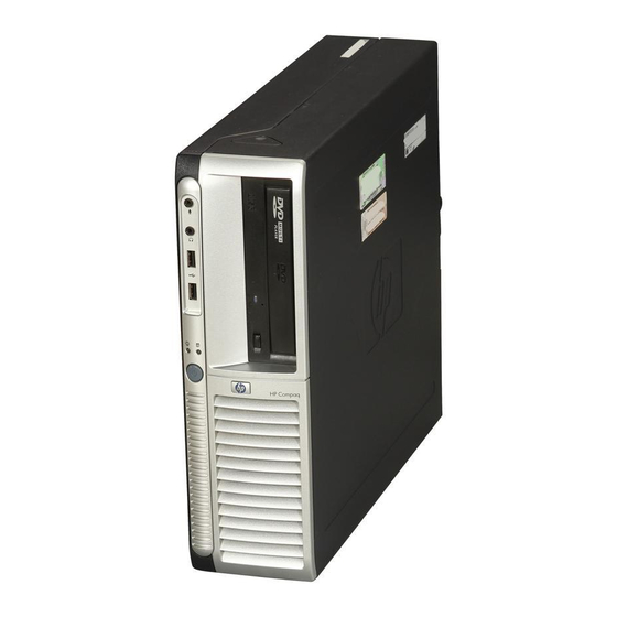
Introduction The HP Compaq dx7200 and dc7600 Series Business Desktop Computers (Figure 2-1) deliver an outstanding combination of manageability, serviceability, and compatibility for enterprise environments. Based on the Intel Pentium 4 processor with the Intel 945G Chipset, these systems emphasize performance along with industry compatibility. These models feature architectures incorporating the PCI bus. -
Page 18: Features
Energy Star compliant ■ Security features including: ❏ Flash ROM Boot Block ❏ Diskette drive disable, boot disable, write protect ❏ Power-on password ❏ Administrator password ❏ Serial/parallel port disable ■ PS/2 enhanced keyboard ■ PS/2 scroll mouse www.hp.com Technical Reference Guide... - Page 19 2 full-height [5] 2 full-height [5] Standard Not supported Not supported Sensor only Both 200-watt 240-watt 240-watt Active PFC Active PFC Active PFC www.hp.com System Overview dx7200 dc7600 µATX µATX Standard Standard 4 GB 4 GB 4 GB DDR2 DDR2...
-
Page 20: Mechanical Design
2.3 Mechanical Design This guide covers five form factors: ■ Ultra Slim Desktop (USDT)—Very slim design that can be used in a tradition desktop (horizontal) orientation or as a small tower mounted in the supplied tower stand. ■ Small Form Factor (SFF)—A small-footprint desktop requiring minimal desk space. -
Page 21: Cabinet Layouts
2.3.1 Cabinet Layouts Front Views Figure 2-2 shows the front panel components of the Ultra Slim Desktop (USDT) format factor. Item Description MultiBay device bay MultiBay device eject lever Microphone audio In jack Headphone audio Out jack Figure 2-2. HP Compaq dc7600 USDT Front View... - Page 22 Diskette drive media door CD-ROM drive acitvity LED Diskette drive eject button CD-ROM media tray CD-ROM drive open/close button Figure 2-3. HP Compaq dc7600 SFF Front View Item Decription Microphone audio In jack Headphone audio Out jack USB ports 7, 8...
- Page 23 Microphone audio in jack Headphone audio out jack USB ports 7, 8 hard drive activity LED Power LED Power button Figure 2-4. HP Compaq dx7200 ST Front View Technical Reference Guide Item Decription Diskette drive activity LED Diskette media door...
- Page 24 CD-ROM drive CD-ROM drive activity LED Diskette drive media door Diskette drive activity LED Diskette drive eject button USB ports 7, 8 Figure 2-5. HP Compaq dx7200 MT Front View Item Decription CD-ROM drive open/close button Power button Power LED...
- Page 25 CD-ROM drive CD-ROM drive activity LED Diskette drive media door Diskette drive activity LED Diskette drive eject button Hard drive activity LED Figure 2-6. HP Compaq dc7600 CMT Front View Technical Reference Guide Item Decription CD-ROM drive open/close button Power button...
- Page 26 DB-15 female connector for video monitor. 1/8 inch, 3-conductor phone jack (color-coded blue) for stereo audio line input. 1/8-inch, 3-conductor phone jack (color-coded green) for stereo audio line output. 1/8-inch, 3-conductor phone jack (color-coded pink) for stereo audio microphone input. www.hp.com Technical Reference Guide...
-
Page 27: Chassis Layouts
UIltra Slim Desktop Chassis The Ultra Slim Desktop (USDT) chassis used for the HP Compaq dc7600 models uses a compact, space-saving form factor. Item... - Page 28 Small Form Factor / Slim Tower Chassis The chassis layouts for the Small Form Factor (SFF) used for the HP Compaq dc7600 models and the Slim Tower (ST) used for the HP Comapq dx7200 models are shown in Figure 2-8. Features include: ■...
-
Page 29: Microtower Chassis
Microtower Chassis Figure 2-9 shows the layout for the Microtower (MT) chassis used for the HP Compaq dx7200 models. Features include: ■ Externally accessible drive bay assembly. ■ Easy access to expansion slots and all socketed system board components. Item... - Page 30 System Overview Convertible Minitower Figure 2-10 shows the layout for the Convertible Minitower (CMT) chassis in the minitower configuration used for HP Compaq dc7600 models. Features include: ■ Externally accessible drive bay assembly may be configured for minitower (vertical) or desktop (horizontal) position.
-
Page 31: Board Layouts
Power button, power LED, HD LED, temp sensor header Chassis speaker connector Front panel audio connector Chassis fan, secondary Front panel USB port connector Chassis fan connector Processor fan connctor DIMM sockets (3) MultiBay riser connector Battery Power supply connector www.hp.com System Overview 2-15... - Page 32 See SFF and ST rear chassis illustrations for externally accessible I/O connectors. Figure 2-12. SFF/ST System Board 2-16 4 5 6 7 8 Item www.hp.com Description Power button, power LED, HD LED header Front panel audio header Chassis speaker connector...
- Page 33 Password clear jumper header Power LED/button, HD LED header CMOS clear switch SATA #1 connector (white) Internal speaker connector Auxiliary audio input connector Front panel USB port connector PCI expansion board connector [2] Front panel audio connector www.hp.com System Overview 2-17...
-
Page 34: System Architecture
PCI 2.3 card PCI 2.3 card Yes [1] Yes [2] Yes [2] Yes [2] Yes [2] Optional [3] Standard [4] Standard [4] www.hp.com PCI-E or PCI-E or PCI 2.3 card PCI 2.3 card Standard [4] Standard [4] Technical Reference Guide... - Page 35 PEG I/F [1] SATA 82801 PATA ICH8 LPC I/F Audio I/F PCI Cntlr. PCI 2.3 slot(s) PCI Express x1 slot [1] www.hp.com System Overview Ch A DDR2 SDRAM Ch B DDR2 SDRAM USB Ports 1-8 Serial I/F [1] Parallel I/F [1] SCH5307 I/O Cntlr.
-
Page 36: Intel Pentium 4 Processor
The processor heatsink/fan assembly mounting differs between form factors. Always use the same assembly or one of the same type when replacing the processor. Refer to the applicable Service Reference Guide for detailed removal and replacement procedures of the heatsink/fan assembly and the processor. 2-20 www.hp.com Technical Reference Guide... -
Page 37: Chipset
PCI 2.3 bus I/F PCI Express x1 LPC bus I/F SMBus I/F IDE I/F with SATA and PATA support HD audio interface RTC/CMOS IRQ controller Power management logic USB 1.1/2.0 controllers supporting eight (8) ports Loaded with HP/Compaq BIOS www.hp.com System Overview 2-21... -
Page 38: Support Components
Fan control and monitoring Power supply voltage monitoring SMBus and Low Pin Count (LPC) bus I/F 10/100/1000 Fast Ethernet network interface controller. Audio mixer One digital-to-analog 2-channel converter Two analog-to-digital 2-channel converters Analog I/O 2-channel audio support www.hp.com Technical Reference Guide... -
Page 39: Mass Storage
100BASE-TX, or 1000BASE-T operation with a local area network and includes power-down, wake-up, and Alert-On-LAN (AOL), and Alert Standard Format (ASF) features. An RJ-45 connector with status LEDs is provided on the rear panel. Technical Reference Guide www.hp.com System Overview 2-23... -
Page 40: Graphics Subsystem
Integrated Graphics Controller Hi 2D, Entry 3D Int. PCI Express 8 MB pre-allocated DVMT 3.0 400 MHz 2048x1536 @ 85 Hz Quick Draw, DirectX 9.0, Direct Draw, Direct Show, Open GL 1.4, MPEG 1-2, Indeo 1 RGB www.hp.com Technical Reference Guide... -
Page 41: Specifications
240 watts 300 watts 365 watts 4 A @ 100 VAC 5 A @ 100 VAC 5.4 A @ 100 VAC 6 A @ 100 VAC www.hp.com System Overview Non-operating to 140 F (-30 to 60 C, max. rate of change < 20°C/Hr ) 20 Gs [1] 0.0005 G... - Page 42 [1] System weight may vary depending on installed drives/peripherals. [2] Without MultiBay device installed. [3] Minitower configuration. For desktop configuration, swap Height and Width dimensions. [4] Applicable to unit in desktop orientation only and assumes reasonable type of load such as a monitor. 2-26...
- Page 43 Average Access Time: Track-to-Track (high/low) Average (high/low) Settling Time Latency Average Technical Reference Guide Table 2-10 Measurement 3.5 in 1.44 MB/720 KB diskette 1/3 bay (1 in) 3 ms/6 ms 94 ms/169 ms 15 ms 100 ms www.hp.com System Overview 2-27...
-
Page 44: Optical Drive Specifications
0.14 mW GaAs 790 +/- 25 nm <100 ms <150 ms 0.7 Vrms 128 KB www.hp.com 48/24/28x CD-RW Drive Mode 1,2, Mixed Mode, CD-DA, Photo CD, Cdi, CD-XA CD-R, CD-RW CD-ROM, 4.8 Kb/s; CD-ROM/CD-R, 1.5-6 Kb/s CD-R, 2.4 Kbps (sustained);... -
Page 45: Hard Drive Specifications
1.2 ms 0.8 ms 8.0 ms 9.0 ms 18 ms 17 ms 78,165,360 156,301,488 5400/7200 5400/7200 SMART III SMART III www.hp.com System Overview 160 GB 3.5 in SATA 300 Gb/s 0.8 ms 9 ms 17 ms 320,173,056 7200 RPM SMART III... - Page 46 System Overview 2-30 www.hp.com Technical Reference Guide...
-
Page 47: Processor/Memory Subsystem
Pentium 4 processor (3.2), page 3-2 ■ Memory subsystem (3.3), page 3-4 Technical Reference Guide Processor/Memory Subsystem XMM1 Ch A FSB I/F DIMM SDRAM 82945G GMCH Cntrl Ch B DIMM XMM3 www.hp.com XMM2 [1] Ch A DIMM Ch B DIMM XMM4... -
Page 48: Pentium 4 Processor
Quad-pumped Front Side Bus (FSB)—The FSB uses a 200-MHz clock for qualifying the buses' control signals. However, address information is transferred using a 2x strobe while data is transferred with a 4x strobe, providing a maximum data transfer rate that is four times that of earlier processors. www.hp.com Technical Reference Guide... -
Page 49: Processor Upgrading
3.80 GHz 7.6 GHz 3.60 GHz 7.2 GHz 3.40 GHz 6.8 GHz 3.20 GHz 6.4 GHz 3.00 GHz 6.0 GHz www.hp.com Processor/Memory Subsystem Adv.. Cache Data Transfer Cache Cache FSB speed (max. data transfer rate) FSB Speed L2 Cache Size... -
Page 50: Memory Subsystem
The SPD format supported by these systems complies with the JEDEC specification for 128-byte EEPROMs. This system also provides support for 256-byte EEPROMs to include additional HP-added features such as part number and serial number. The SPD format as supported in this system (SPD rev. 1) is shown in Table 3-1. - Page 51 256-MB none none none 512-MB none none none 1-GB 1-GB 1-GB 1-GB 1-GB www.hp.com Processor/Memory Subsystem Socket 4 Total none 128-MB none 256-MB (dual-channel) none 384-MB (dual-channel) 128-MB 512-MB (dua- channel) none 256-MB none 512-MB (dual-channel) none...
- Page 52 [8] Field specified as optional by JEDEC but required by this system. [9] HP usage. This system requires that the DIMM EEPROM have this space available for reads/writes. [10] Serial # in ASCII format (MSB is 133). Intended as backup identifier in case vender data is invalid.
- Page 53 IGC (1-32 MB) TSEG Main Memory 0100 0000h 00FF FFFFh Main Memory 0010 0000h 000F FFFFh BIOS Extended BIOS Expansion Area Legacy Video Base Memory 0000 0000h www.hp.com Processor/Memory Subsystem 4 GB Top of DRAM 16 MB 1 MB 640 KB...
- Page 54 Processor/Memory Subsystem www.hp.com Technical Reference Guide...
-
Page 55: System Support
Direct Media Interface (DMI) links the GMCH and ICH8 components and operates as a subset of the PCI bus. All PCI slots and the NIC function internal to the ICH8 reside on PCI bus #2. Technical Reference Guide System Support www.hp.com... -
Page 56: Pci 2.3 Bus Operation
82801 ICH8 PCI Bus 1 Cntlr PCI Exp. Function Port 2 Function Cntlr PCI Express x1 slot [1] PCI 2.3 slot(s) www.hp.com RGB Monitor PCI Express x16 graphics slot [1] SATA USB I/F HD Audio Cntlr Bridge Cntlr Cntlr Function... - Page 57 Technical Reference Guide PCI Configuration Address Register I/O Port 0CF8h, R/W, (32-bit access only) 31..0 Device Reserved Number Number IDSEL (only one signal line asserted) www.hp.com System Support Function Configuration Data. 2 1 0 [1] Function Register Number Index Function...
- Page 58 [1] Function not used in these systems. [2] SFF, ST, & CMT form factors only. [3] CMT form factor with PCI expansion board. Table 4-1 PCI Component Configuration Access Notes Function # Device # www.hp.com PCI Bus IDSEL Wired to: AD20 AD25 AD27 AD29...
- Page 59 Prefetch. Mem. Limit Secondar y Status Lat.Tmr Lat. Timer Line Size BIST Revision ID Command Vendor ID Not required www.hp.com System Support 24 23 16 15 Device-Specific Area Brid ge Control Int. Pin Int. Line Ex pansion ROM Base Address Reserved...
-
Page 60: Pci Express Bus Operation
Message Signal Interrupt (MSI) introduced with the PCI 2.2 specification. The MSI method eliminates the need for hard-wired sideband signals by incorporating those functions into packets. Table 4-3. REQ/GNT Line Note REQ0/GNT0 REQ1/GNT1 REQ3/GNT3 REQ4/GNT4 www.hp.com Technical Reference Guide... - Page 61 Table 4-4: Table 4-4. PCI Express Byte Transfer Transfer Transfer Byte # Lane # Lane # Technical Reference Guide System Board Device A Transfer Lane # www.hp.com System Support PCI Express Card Device B...
-
Page 62: Option Rom Mapping
4.2.5 PCI Power Management Support This system complies with the PCI Power Management Interface Specification (rev 1.0). The PCI Power Management Enable (PME-) signal is supported by the chipset and allows compliant PCI peripherals to initiate the power management routine. www.hp.com Technical Reference Guide... -
Page 63: Pci Connectors
C/BE2- +3.3 VDC FRAME- IRDY- +3.3 VDC TRDY- DEVSEL- STOP- LOCK- +3.3 VDC PERR- SDONE n +3.3 VDC SBO- SERR- www.hp.com System Support B Signal A Signal +3.3 VDC C/BE1- AD15 AD14 +3.3 VDC AD13 AD12 AD11 AD10 AD09 AD08... -
Page 64: Pci Express Connectors
PERp5 PERn5 PETp6 PETn6 PERp6 PERn6 PETp7 PETn7 PERp7 PRSNT2# PERn7 PETp8 RSVD PETn8 PERp8 PERn8 PETp9 PETn9 PERp9 www.hp.com B Signal A Signal PERn9 PETp10 PETn10 PERp10 PERn10 PETp11 PETn11 PERp11 PERn11 PETp12 PETn12 PERp12 PERn12 PETp13 PETn13 PERp13... -
Page 65: System Resources
A serialized interrupt stream is then routed to the ICH component. Interrupts may be processed in one of two modes (selectable through the F10 Setup utility): ■ 8259 mode ■ APIC mode These modes are described in the following subsections. Technical Reference Guide www.hp.com System Support 4-11... - Page 66 Sec. IDE I/F controller (not available on SATA units) IRQ3 Serial port (COM2) IRQ4 Serial port (COM1) IRQ5 Network interface controller IRQ6 Diskette drive controller IRQ7 Parallel port (LPT1) IRQ2 NOT AVAILABLE (Cascade from interrupt controller 2) www.hp.com Technical Reference Guide...
-
Page 67: Apic Mode
Slot 3 Slot 4 INTA- INTD- INTB- INTD- — — — — INTB- INTA- INTC- INTA- — — — — — — — — INTC- INTB- INTD- INTB- INTD- INTC- INTA- INTC- — — — — www.hp.com System Support 4-13... -
Page 68: Non-Maskable Interrupts
Parity errors detected on a PCI bus (activating SERR- or PERR-). ■ Microprocessor internal error (activating IERRA or IERRB) The SERR- and PERR- signals are routed through the ICH8 component, which in turn activates the NMI to the microprocessor. 4-14 Table 4-8. www.hp.com Technical Reference Guide... - Page 69 APM BIOS to service the SMI- according to the cause of the timeout. Although the SMI- is primarily used for power management the interrupt is also employed for the QuickLock/QuickBlank functions as well. Technical Reference Guide www.hp.com System Support 4-15...
-
Page 70: Direct Memory Access
The DMA logic is accessed through two types of I/O mapped registers; page registers and controller registers. 4-16 Table 4-9. Device ID Spare Audio subsystem Diskette drive Parallel port Cascade for controller 1 Spare Spare Spare www.hp.com Technical Reference Guide... - Page 71 Address lines LA23..17, SA18,19 are driven low. Technical Reference Guide Table 4-10. Page Register I/O Port 087h 083h 081h 082h 08Bh 089h 08Ah 08Fh [see note] 8-Bit DMA Controller A15..A00 16-Bit DMA Controller A16..A01, (A00 = 0) www.hp.com System Support 4-17...
- Page 72 000h 001h 001h 002h 002h 003h 003h 004h 004h 005h 005h 006h 006h 007h 007h 00Dh 00Ch 00Dh 00Eh www.hp.com Controller 2 0D0h 0D0h 0D6h 0D4h 0DEh 0D2h 0C0h 0C0h 0C2h 0C2h 0C4h 0C4h 0C6h 0C6h 0C8h 0C8h 0CAh 0CAh...
-
Page 73: Real-Time Clock And Configuration Memory
Register A Memory Area Year (128 bytes) Month Date of Month Day of Week Standard Config. Hours (Alarm) Memory Area Hours (Timer) (114 bytes) Minutes (Alarm) Minutes (Timer) RTC Area Seconds (Alarm) (14 bytes) Seconds (Timer) CMOS www.hp.com System Support 4-19... -
Page 74: Standard Cmos Locations
4-20 Table 4-12. Configuration Memory (CMOS) Map Location 2Eh-2Fh 30h-31h 37h-3Fh 40-FFh www.hp.com Function System board ID System architecture data Auxiliary peripheral configuration Speed control external drive Expanded/base mem. size, IRQ12 Miscellaneous configuration Hard drive timeout System inactivity timeout... -
Page 75: Setup Password
Through Setup, the user can set this function to be used by Alert-On-LAN and or one of three levels of support for a “cover removed” condition: Technical Reference Guide www.hp.com System Support 4-21... -
Page 76: Power Management
RTC Alarm Wake On LAN (w/NIC) Serial Port Ring Keyboard Mouse 4-22 System Wakes From Suspend or soft-off Suspend or soft-off Suspend or soft-off Suspend or soft-off Suspend or soft-off Suspend only Suspend only Suspend only www.hp.com Technical Reference Guide... -
Page 77: System Status
7 [2] Blinks red 8 times @ I Hz [1] 8 [2] Blinks red 9 times @ I Hz [1] 9 [2] Blinks red 10 times @ I Hz [1] None www.hp.com System Support Action Required None None None None... -
Page 78: Register Map And Miscellaneous Functions
PCI Configuration Data (byte, word, or dword access) NOTE: Assume unmarked gaps are unused, reserved, or used by functions that employ variable I/O address mapping. Some ranges may include reserved addresses. 4-24 Table 4-14 System I/O Map www.hp.com Technical Reference Guide... -
Page 79: Sch5307 I/O Controller Functions
PLL / Oscillator Control Reserved Configuration Address (Low Byte) Configuration Address (High Byte) 28-2Fh Reserved NOTE: For a detailed description of registers refer to appropriate documentation available from SMC Corporation. Technical Reference Guide Table 4-15. Reset Value www.hp.com System Support 4-25... - Page 80 Legacy/ACPI power button mode control—The SCH5307 receives the pulse signal from the system's power button and produces the PS On signal according to the mode (legacy or ACPI) selected. Refer to chapter 7 for more information regarding power management. 4-26 www.hp.com Technical Reference Guide...
-
Page 81: Input/Output Interfaces
100 MB/s. IDE Programming The IDE interface is configured as a PCI device during POST and controlled through I/O-mapped registers at runtime. Non-DOS (non-Windows) operating systems may require using Setup (F10) for drive configuration. Technical Reference Guide Input/Output Interfaces www.hp.com... - Page 82 EIDE PCI Configuration Registers (82801) Reset PCI Conf. Value Addr. 8086h 0F..1Fh 20-23h 0000h 2C, 2Dh 0280h 2E, 2Fh 30..3Fh 40-43h 4A-4Bh www.hp.com Reset Register Value Reserved 0’s BMIDE Base Address Subsystem Vender ID 0000h Subsystem ID 0000h Reserved 0’s Pri./Sec. IDE Timing 0’s Slave IDE Timing Sync.
-
Page 83: Ide (Pata) Connector
The USDT form factor does not include 40-pin IDE connctor. The IDE interface and hard drive power signals are both a part of the MultiBay interface used on the USDT form factor. Technical Reference Guide Table 5-2. Default Register 0000 0000h 0000 0000h www.hp.com Input/Output Interfaces Value... - Page 84 40-Pin IDE (PATA) Connector Pinout Signal IOW- IOR- IORDY CSEL DAK- IRQn IO16- DSKPDIAG CS0- CS1- HDACTIVE- www.hp.com Description DMA Request Ground I/O Write [1] Ground I/O Read [2] Ground I/O Channel Ready [3] Cable Select DMA Acknowledge Ground Interrupt Request [4]...
-
Page 85: Sata Interfaces
Register Value Addr. 8086h 0F..1Fh 24D1h 10-17h 0000h 18-1Fh 02B0h 20-23h 2C, 2Dh 2E, 2Fh 40-57h www.hp.com Input/Output Interfaces Reset Register Value Reserved 0’s Pri. Cmd, Cntrl. 1 (both) Addrs. Sec. Cmd, Cntrl. 1 (both) Addrs. BMstr Base Address Subsystem Vender ID... -
Page 86: Sata Connector
Bus Master IDE Command (Secondary) Bus Master IDE Status (Secondary) Bus Master IDE Descriptor Pointer (Secondary Pin 1 Table 5-6. Description RX positive Ground Holding clip Holding clip www.hp.com Default Value 0000 0000h 0000 0000h Pin 7 Technical Reference Guide... -
Page 87: Diskette Drive Interface
1. Write 07h to I/O register 2Eh. 2. Write 00h to I/O register 2Fh (this selects the diskette drive I/F). 3. Write 30h to I/O register 2Eh. 4. Write 01h to I/O register 2Fh (this activates the interface). Technical Reference Guide www.hp.com Input/Output Interfaces... - Page 88 For detailed configuration register information refer to the SMSC data sheet for the SCH5307 I/O component. Table 5-7. Function Activate Base Address Interrupt Select DD Mode DD Option DD Type DD 0 DD 1 www.hp.com Reset Value 03F0h Technical Reference Guide...
- Page 89 <5,4> Motor 1, 0 enable (active high) <3> DMA enable (active high) <2> Reset (active low) <1,0> Drive select (00 = Drive 1, 01 = Drive 2, 10 = Reserved, 11 = Tape drive) Tape Drive Register (available for compatibility) www.hp.com Input/Output Interfaces...
- Page 90 <7> DSK CHG status (records opposite value of pin) <6..0> Reserved (0’s) Configuration Control Register (CCR): <7..2> Reserved <1,0> Data rate select (00 = 500 Kb/s, 01 = 300 Kb/s, 10 = 250 Kb/s, 11 = 2/1 Mb/s) www.hp.com Technical Reference Guide...
-
Page 91: Diskette Drive Connector
Signal DIR- STEP- WR DATA- WR ENABLE- TRK 00- WR PRTK- RD DATA- SIDE SEL- DSK CHG- www.hp.com Input/Output Interfaces Description Drive head direction control Ground Drive head track step cntrl. Ground Write data Ground Enable for WR DATA- Ground... -
Page 92: Serial Interface
Address selection and activation of the serial interface are affected through the PnP configuration registers of the SCH5307 I/O controller. 5-12 Table 5-10. DB-9 Serial Connector Pinout Signal www.hp.com Description Data Set Ready Request To Send Clear To Send Ring Indicator... - Page 93 2FCh Modem Control Register 3FDh 2FDh Line Status Register 3FEh 2FEh Modem Status Technical Reference Guide Table 5-11. Function Activate Base Address MSB Base Address LSB Interrupt Select Mode Register Table 5-12. Serial Interface Control Registers www.hp.com Input/Output Interfaces 5-13...
-
Page 94: Parallel Interface
EPP timing. A watchdog timer is used to prevent system lockup. Five additional registers are available in EPP mode to handle 16- and 32-bit CPU accesses with the parallel interface. Address decoding includes address lines A0, A1, and A2. 5-14 www.hp.com Technical Reference Guide... -
Page 95: Extended Capabilities Port Mode
The parallel interface configuration registers are listed in the following table: Parallel Interface Configuration Registers Index Address Function Activate Base Address MSB Base Address LSB Interrupt Select DMA Channel Select Mode Register Mode Register 2 Technical Reference Guide Table 5-13. Reset Value www.hp.com Input/Output Interfaces 5-15... - Page 96 LPT1 = 378h LPT2 = 278h LPT3 = 3BCh 5-16 Table 5-14. Mode Mode Ports Ports LPT1,2,3 LPT1,2 LPT1,2,3 LPT1,2 LPT1,2,3 LPT1,2 LPT1,2 LPT1,2 LPT1,2 LPT1,2 LPT1,2 www.hp.com Mode Ports LPT1,2,3 LPT1,2,3 LPT1,2,3 LPT1,2,3 LPT1,2,3 LPT1,2,3 LPT1,2,3 LPT1,2,3 LPT1,2,3 Technical Reference Guide...
-
Page 97: Parallel Interface Connector
[4] EPP mode: Reset ECP modes: Initialize or Reverse Req. Technical Reference Guide Table 5-15. DB-25 Parallel Connector Pinout Signal ERR- INIT- SLCTIN- www.hp.com Input/Output Interfaces Function Line Feed [2] Error [3] Initialize Paper [4] Select In / Address. Strobe [1] Ground Ground... -
Page 98: Keyboard/Pointing Device Interface
25 us Tch (Clock High) 25 us Th (Data Hold) 0 us Tss (Stop Bit Setup) 8 us Tsh (Stop Bit Hold) 15 us www.hp.com Parity Stop (MSb) 80 us 35 us 45 us 25 us 20 us 25 us... - Page 99 Resets keyboard to power-on default state and halts scanning pending next 8042 command. Resets keyboard to power-on default state and enable scanning. Clears keyboard buffer and sets default scan code set. [1] www.hp.com Input/Output Interfaces 5-19...
-
Page 100: Pointing Device Interface Operation
Clears keyboard buffer and prepares to receive key ID. [1] Clears keyboard buffer and prepares to receive key ID. [1] Clears keyboard buffer and prepares to receive key ID. [1] 8042 detected error in keyboard transmission. Resets program, runs keyboard BAT, defaults to Mode 2. www.hp.com Technical Reference Guide... - Page 101 Status register to DATA. The input buffer is used for transferring data from the system to the keyboard. All data written to this port by the CPU will be transferred to the keyboard except bytes that follow a multibyte command that was written to 64h Technical Reference Guide Table 5-17. www.hp.com Input/Output Interfaces 5-21...
- Page 102 Enable pointing device. This command clears bit <5> of the 8042 command byte, activating the clock line of the pointing device interface. 5-22 Table 5-18. CPU Commands to the 8042 www.hp.com Technical Reference Guide...
- Page 103 Pulse output port. Controls the pulsing of bits <3..0> of the output port (0 = pulse, 1 = don’t pulse). Note that pulsing bit <0> will reset the system. Technical Reference Guide Table 5-18. (Continued) CPU Commands to the 8042 www.hp.com Input/Output Interfaces 5-23...
-
Page 104: Keyboard/Pointing Device Interface Connector
Figure 5-7. PS/2 Keyboard or Pointing Device Interface Connector (as viewed from rear of chassis) Keyboard/Pointing Device Connector Pinout Signal Description DATA Data Not Connected Ground 5-24 Table 5-19. Signal Description + 5 VDC Power Clock Not Connected www.hp.com Technical Reference Guide... -
Page 105: Universal Serial Bus Interface
82801 ICH8 Data 0 Data 1 Data 2 Data 3 Data 4 Data 5 Data 6 Data 7 www.hp.com Input/Output Interfaces Rear Panel USB Port 1 USB Port 2 USB Port 3 USB Port 4 USB Port 5 USB Port 6... -
Page 106: Usb Data Formats
(11 bits) Sync Field PID Field (8 bits) (8 bits) (0-1023 bytes) Sync Field PID Field (8 bits) (8 bits) www.hp.com ENDP. Field CRC Field (4 bits) (5 bits) CRC Field (5 bits) Data Field CRC Field (16 bits) Technical Reference Guide... -
Page 107: Usb Programming
USB Interface Configuration Registers Reset PCI Config. Value Address 8086h 0Eh 20-23h 0000h 2C, 2Dh 0280h 3Ch C0, C1h www.hp.com Input/Output Interfaces Reset Register Value Header Type I/O Space Base Address Sub. Vender ID Interrupt Line Interrupt Pin Serial Bus Release No. -
Page 108: Usb Connector
These systems provide type-A USB ports as shown in Figure 5-10 below. Figure 5-10. Universal Serial Bus Connector (Female) Signal USB- 5-28 Table 5-21. USB Control Registers Table 5-22. USB Connector Pinout Description +5 VDC Data (minus) www.hp.com Default Value 0000h 0000h 0000h 0000h 0000h 0080h 0080h Signal Description USB+... -
Page 109: Usb Cable Data
Maximum Length 0.036 Ω 16.4 ft (5.00 m) 0.057 Ω 9.94 ft (3.03 m) 0.091 Ω 6.82 ft (2.08 m) 0.145 Ω 4.30 ft (1.31 m) 0.232 Ω 2.66 ft (0.81 m) Insulation color Green White Black www.hp.com Input/Output Interfaces 5-29... -
Page 110: Audio Subsystem
[2] SSF, ST, MT, and CMT only. On USDT form facter, aux audio is routed through MultiBay interface. Figure 5-11. Audio Subsystem Functional Block Diagram 5-30 PC Beep HD Audio I/F Speaker Audio (L+R) Header Header ALC260 Headphone HD Audio Audio (L/R) Codec Line Audio Out (L/R) www.hp.com Header Audio Headphones Line Out Technical Reference Guide... -
Page 111: Hd Audio Controller
SYNC Command Stream RST# NOTE: Clock not drawn to scale. Figure 5-12. HD Audio Interface Protocol Technical Reference Guide Frame Tag A Tag B Stream B Stream A Tag C Stream C Response Stream www.hp.com Input/Output Interfaces Frame Start 5-31... -
Page 112: Hd Audio Link Bus
Mic Audio In CD Audio In Line Audio In PC Beep In Line Audio Gain HP Audio Gain NOTE: The audio codec includes two ADCs. However, only one is typcially used. All audio lines represent both left and right channel information. -
Page 113: Audio Programming
Subsystem Vender ID 0000h 2E-2Fh Subsystem ID 0280h Capability List Pointer Interrupt Line Interrupt Pin HD Audio Control Traffic Class Select 4C, 4Dh Docking Control/Status 50-14Fh -HD audio functions www.hp.com Input/Output Interfaces Value on Reset 0000h 0000h 0’s 0080h 5-33... - Page 114 Get Beep Generator F0Ah 00Ah Set Beep Generator 70Ah 002h Get GPIO Data F15h F05h Set GPIO Data 715h www.hp.com Verb Value Get GPIO Enable Mask F16h Set GPIO Enable Mask 716h Get GPIO Direction F17h Set GPIO Direction 717h Get GPIO Unsol.
-
Page 115: Audio Specifications
44.1-, 48-, 96-, & 192-KHz [1] 44.1-, 48-, & 96-KHz [1] 24-bit 20-bit .283 Vp-p 2.83 Vp-p 64K ohms 64K ohms 200 ohms 32 0hms 95 db (nom) 1.5 watts 1 db -94.5 db 10 – 22,000 Hz 450–4000 Hz www.hp.com Input/Output Interfaces 5-35... -
Page 116: Network Interface Controller
AC outlet. Controlling unit power through a switchable power strip will, with the strip turned off, disable any wake, alert, or power mangement functionality. 5-36 Green LED Tx/Rx Data Tx/Rx Data LAN I/F Yellow LED www.hp.com RJ-45 Connector Technical Reference Guide... -
Page 117: Wake-On-Lan Support
Flexible packet filtering—Packets that match defined CRC signature The PROSet Application software (pre-installed and accessed through the System Tray or Windows Control Panel) allows configuration of operational parameters such as WOL and duplex mode. Technical Reference Guide www.hp.com Input/Output Interfaces 5-37... -
Page 118: Nic Programming
The Broadcom BCM5752 is configured as a PCI device and controlled through registers mapped in variable I/O space. The BIOS for the BCM5782 is contained within the HP/Compaq BIOS in system ROM. Refer to Broadcom documentation for details regarding BCM5782 register programming. -
Page 119: Nic Specifications
MS Windows NT 3.51 & 4.0 Novell Netware 3.x, 4.x, 5x Novell Netware/IntraNetWare SCO UnixWare 7 Linux 2.2, 2.4 PXE 2.0 Intel PRO/100 Boot Agent (PXE 3.0, RPL) PCI Express x1 ACPI, PCI Power Management Spec. www.hp.com Input/Output Interfaces 5-39... - Page 120 Input/Output Interfaces 5-40 www.hp.com Technical Reference Guide...
-
Page 121: Integrated Graphics Subsystem
(refer to section 6.4 for more information on upgrading the graphics subsystem). This chapter covers the following subjects: ■ Functional description (6.2), page 6-2 ■ Display Modes (6.3), page 6-4 ■ Upgrading graphics (6.4) , page 6-5 ■ VGA Monitor connector (6.5), page 6-6 Technical Reference Guide www.hp.com... -
Page 122: Functional Description
■ Provides two serial digital video out (SDVO) channels for use by an appropriate ADD2 accessory card. 82945G GMCH Integrated Graphics Controller PCI-E & SDVO Data PCI Expr. I/F www.hp.com DDR2 SDRAM SDRAM (System Controller Memory) Technical Reference Guide... - Page 123 (video) may be reported in a message on the screen, depending on the operating system and/or applications running on the machine. Technical Reference Guide Integrated Graphics Subsystem Maximum Memory Allocation 8-32 MB 8-64 MB 8-128 MB www.hp.com...
-
Page 124: Display Modes
Single or dual channel memory ■ Number and type of monitors ✎ The IGC is designed for optimum performance with multi-sync analog monitors. Digital displays may not provide an image as high in quality, depending on resolution. www.hp.com Technical Reference Guide... -
Page 125: Upgrading Graphics
PCI card in the PCI 2.3 slot (assuming no riser cards are installed ). Depending on accessory, upgrading through the PCI Express x16 slot can provide digital monitor support and/or dual-monitor support allowing display-cloning or extended desktop functionality. Software drivers may need to be downloaded for specific cards. -
Page 126: Vga Monitor Connector
B GND Green Analog Ground NOTES: [1] Fuse automatically resets when excessive load is removed. Table 6-1. DB-15 Monitor Connector Pinout Signal HSync VSync www.hp.com Description +5 VDC (fused) [1] Ground Not Connected DDC2-B Data Horizontal Sync Vertical Sync DDC2-B Clock... -
Page 127: Power And Signal Distribution
Technical Reference Guide Power and Signal Distribution System Board CPU, slots, Chipsets, Logic, & Voltage Regulators +3.3 VDC 5 AUX +5 VDC +12 VDC Spd [1] Power Supply Assembly www.hp.com -12 VDC +12 VccP +3.3 VDC +5 VDC Drives +12 VDC... -
Page 128: Power Supply Assembly
3.0 A + 5 % 0.1 A 7.5 A + 5 % 0.1 A 12.5 A + 10 % 0.0 A 0.15 A www.hp.com Surge Max. Current [2] Ripple 12.0 A 50 mV 10.0 A 50 mV 2.0 A 50 mV 17.0 A... - Page 129 3.00 A + 5 % 0.20 A 12.0 A + 5 % 0.00 A 14.5 A + 10 % 0.00 A 0.15 A www.hp.com Power and Signal Distribution Surge Max. Current Ripple 19.0 A 50 mV 25.0 A 50 mV 2.00 A...
-
Page 130: Power Control
(this operation is meant as a guard if the OS is hung). Pressed and Held At least Four Seconds Before Release: If the button is held in for at least four seconds and then released, PS On is negated, de-activating the power supply. www.hp.com Technical Reference Guide... -
Page 131: Wake Up Events
System dead. Press and hold power button for less than 4 seconds. If HD LED turns green then check voltage select switch setting or expansion cards. If no LED light then check power button/power supply cables to system board or system board. www.hp.com Power and Signal Distribution... - Page 132 A power management event that asserts the PME- signal on the PCI bus can be enabled to cause the power control logic to generate the PS On. Note that the PCI card must be PCI ver. 2.2 compliant to support this function. www.hp.com Technical Reference Guide...
-
Page 133: Power Management
< 5 sec. after keyboard, pointing device, or power button action <25 sec. after power button Minimum <35 sec. after power button None www.hp.com Power and Signal Distribution OS Restart Required action action action — —... -
Page 134: Power Distribution
The power supply assembly includes a multi-connector cable assembly that routes +3.3 VDC, +5 VDC, +5 VDC STB, +12 VC, and -12 VDC to the system board as well as to the individual drive assemblies. Figure 7-2 shows the power supply cabling for the Ultra Slim Desktop form factor. Power Supply... - Page 135 Technical Reference Guide Pin 3 Pin 4 Pin 5 Pin 6 Pin 7 PS On Pwr Gd +3.3 VccP VccP www.hp.com Power and Signal Distribution 1 2 3 4 P4, P5 Pin 8 Pin 9 +3.3 +3.3 Tach +3.3 sns +3.3...
- Page 136 Figure 7-4. MT Power Cable Diagram 7-10 Pin 3 Pin 4 Pin 5 Pin 6 Pin 7 PS On VccP VccP +5.08 www.hp.com P9, P10 P2-P6 1 2 3 4 Pin 8 Pin 9 5 aux +3.3 Open Technical Reference Guide...
- Page 137 Technical Reference Guide Pin 3 Pin 4 Pin 5 Pin 6 Pin 7 PS On VccP VccP +5.08 www.hp.com Power and Signal Distribution P4, P5, P9, P10 P6, P7, P11 1 2 3 4 Pin 8 Pin 9 5 aux +3.3 Open...
-
Page 138: Low Voltage Production/Distribution
3.3 VDC AUX Regulator 3 VDC Switch 1.2 Aux V Regulator 2.5 V Regulator 1.5 V Regulator 1.2 V Regulator 1.05 V Regulator www.hp.com VccP Processor 5 VDC PS PCI, SATA, LPT, COM, Diskette logic 5 VDC USB, PS2 Kybd 1.8 VDC Chipset, DIMMs 0.9 VDC... -
Page 139: Signal Distribution
Hard Drive IDE I/F., Diskette I/F., MultiBay CD Audio Daughter Board Keyboard Kybd data Mouse Mouse data Mic In, HP Out Audio Front Panel USB 6,7 Tx/Rx I/O Module www.hp.com Power and Signal Distribution HD LED CD, DVD, or Diskette Drive... - Page 140 Supply PS On, POK Assembly Diskette Diskette I/F SATA I/F SATA Hard Drive CD-ROM IDE I/F Keyboard Kybd data Mouse Mouse data Mic In, HP Out Audio Front Panel USB 6,7 Tx/Rx I/O Module www.hp.com HD LED Technical Reference Guide...
- Page 141 Diskette Diskette I/F SATA I/F Hard Drive CD-ROM IDE I/F. Keyboard Kybd data Mouse data Mic In, HP Out Audio USB 6,7 Tx/Rx I/O Module PCI 2.3 I/F PCI Expansion Daughter Board [1] www.hp.com Power and Signal Distribution Power On...
- Page 142 12 NC 14 Therm Diode C Chassis ID2 15 Chassis ID0 17 Mic In Tip 1 Mic In Sleeve 3 HP Out Right 5 Front Audio Detect 7 HP Out Left 9 2 UART1 DSR- UART2 DTR- 1 4 UART1 RTS-...
-
Page 143: Introduction
ROM flashing (8.2), page 8-2 ■ Boot functions (8.3), page 8-3 ■ Setup utility (8.4), page 8-6 ■ Client management functions (8.5), page 8-16 ■ SMBIOS support (8.6), page 8-18 ■ USB legacy support (8.7), page 8-18 Technical Reference Guide www.hp.com BIOS ROM... -
Page 144: Rom Flashing
All BIOS ROM upgrades are available directly from HP. Flashing is done either locally thrugh F10 setup, the HPQFlash program in a Windows environment, or with the FLASHBIN.EXE utility in a DOS or DOS-like environment. Flashing may also be done by deploying either HPQFlash or FLASHBIN.EXE through the network boot... -
Page 145: Changeable Splash Screen
A corrupted splash screen may be restored by reflashing the BIOS image through F10 setup, running HPQFlash, or running FLASHBIN.EXE. Depending on the system, changing (customizing) the splash screen may only be available with asistance from HP. The splash screen (image displayed during POST) is stored in the BIOS ROM and may be replaced with another image of choice by using the Image Flash utility (Flashi.exe). -
Page 146: Network Boot (F12) Support
1. Program the buffer strength control registers based on SPD data and the DIMM slots that are populated. 2. Determine the common CAS latency that can be supported by the DIMMs. 3. Determine the memory size for each DIMM and program the GMCH accordingly. 4. Enable refresh www.hp.com Technical Reference Guide... -
Page 147: Boot Error Codes
PCA failure. Check/replace system board. 8 beeps Invalid ROM (checksum error). Reflash ROM using CD or replace system board. 9 beeps System powers on but fails to boot. Check power supply, CPU, system board. None Bad option card. www.hp.com BIOS ROM... -
Page 148: Setup Utility
Save Current Settings as Default Saves the current system configuration settings as the default. Restore Factory Settings as Default Restores the factory system configuration settings as the default. Applies the currently selected default settings and clears any established passwords. www.hp.com Technical Reference Guide... - Page 149 BIOS should not be changed. If the selected translation mode is not compatible with the translation mode that was active when the disk was partitioned and formatted, the data on the disk will be inaccessible. www.hp.com BIOS ROM...
- Page 150 BIOS should not be changed. If the selected translation mode is not compatible with the translation mode that was active when the disk was partitioned and formatted, the data on the disk will be inaccessible. www.hp.com Technical Reference Guide...
- Page 151 SATA devices may be accessed in this mode. The SATA and PATA controllers appear as one combined IDE controller. Use this option with Microsoft Windows 98 and earlier operating systems. • PATA Primary Device 0 replaces SATA 1 • PATA Primary Device 1 replaces SATA 3 www.hp.com BIOS ROM...
- Page 152 Setup options, flash the ROM, and make changes to certain plug and play settings under Windows. See the Troubleshooting Guide on the Documentation CD for more information. Allows you to set and enable power-on password. See the Troubleshooting Guide for more information. www.hp.com Technical Reference Guide...
- Page 153 Setup Password requires that the setup password be entered to boot the computer if the sensor detects that the cover has been removed. This feature is supported on select models only. See the Desktop Management Guide on the Documentation CD for more information.
- Page 154 This selection will only appear when at least one drive that supports ATA security command set feature is attached to the system. See the Desktop Management Guide on the Documentation CD for more information. Enable/Disable. Data Execution Prevention Mode help prevent OS security breaches.
- Page 155 F10 to enter Computer (F10) Setup. • I/O APIC Mode (enable/disable). Enabling this feature will allow Microsoft Windows Operating Systems to run optimally. This feature must be disabled for certain non-Microsoft Operating Systems to work properly. www.hp.com BIOS ROM 8-13...
- Page 156 On select models, allows you to enable or disable: • PCI SERR# Generation. • PCI VGA palette snooping, which sets the VGA palette snooping bit in PCI configuration space; only needed when more than one graphics controller is installed. www.hp.com Technical Reference Guide...
- Page 157 ROM space. The default will be to have the NIC option ROM enabled. Displayed only if there are multiple PCI video adapters in the system. Allows you to specify which VGA controller will be the “boot” or primary VGA controller. www.hp.com BIOS ROM 8-15...
-
Page 158: Client Management Functions
Real, 16-, & 32-bit Prot. Real, 16-, & 32-bit Prot. Real, 16-, & 32-bit Prot. Real, 16-, & 32-bit Prot. Real Real Real, 16-, & 32-bit Prot. Real Real Real Real Real, 16-, & 32-bit Prot. www.hp.com Technical Reference Guide... -
Page 159: System Id And Rom Type
512-byte block of drive attribute data while the INT 15, AX=E81Bh is used to retrieve the drive's warranty threshold data. If data is returned indicating possible failure then the following message is displayed: 1720-SMART Hard Drive detects imminent failure Technical Reference Guide System ID 09FCh 09F8h 09F4h 09F0h www.hp.com BIOS ROM 8-17... -
Page 160: Smbios
PS/2 data. The data will be passed to the keyboard controller and processed as in the PS/2 interface. Changing the delay and/or typematic rate of a USB keyboard though BIOS function INT 16 is not supported. 8-18 www.hp.com Technical Reference Guide... -
Page 161: Error Messages And Codes
Not all errors listed in this appendix may be applicable to a particular system model and/or configuration. A.2 Beep/Power LED Codes ✎ Beep and Power LED indictions listed in Table A-1 apply only to HP-branded models. Beeps Power LED None... - Page 162 Current parallel port address is conflicting with another device. NIC BIOS could not read Device ID of embedded NIC. Graphics display controller. Corrupted splash screen image. Restore default image w/flash utility. Processor heat sink fan is not connected. www.hp.com Technical Reference Guide...
- Page 163 Emulation” is set to “Combined IDE Controller” in Computer Setup One or more SATA devices are improperly attached. For optimal performance, the SATA 0 and SATA 1 connectors must be used before SATA 2 and SATA 3. www.hp.com Error Messages and Codes...
- Page 164 A processor is installed for which the BIOS ROM has no patch. Check for ROM update. Electronic serial number has become corrupted. Keyboard failure while Network Server Mode enabled. Keyboard failure while Network Server Mode enabled. www.hp.com Technical Reference Guide...
- Page 165 Protected mode test failed 114-01 Speaker test failed 116-xx Way 0 read/write test failed 162-xx Sys. options failed (mismatch in drive type) 163-xx Time and date not set 164-xx Memory size 199-00 Installed devices test failed www.hp.com Error Messages and Codes...
- Page 166 207-xx ECC failure 210-01 Memory increment pattern test 210-02 Error while saving memory during increment pattern test 210-03 Error while restoring memory during increment pattern test 211-01 Memory random pattern test Table A-4. Memory Error Messages www.hp.com Technical Reference Guide...
- Page 167 Keyboard repeat key test failed 304-02 Unable to enter mode 3 304-03 Incorrect scan code from keyboard 304-04 No Make code observed 304-05 Cannot /disable repeat key feature 304-06 Unable to return to Normal mode www.hp.com Error Messages and Codes...
- Page 168 320x200 mode, color set 0 test failed 509-01 320x200 mode, color set 1 test failed 510-01 640x200 mode test failed 511-01 Screen memory page test failed 512-01 Gray scale test failed 514-01 White screen test failed 516-01 Noise pattern test failed www.hp.com Technical Reference Guide...
- Page 169 612-xx = Sec. diskette drive port addr. conflict 694-00 = Pin 34 not cut on 360-KB drive 697-00 = Diskette type error 698-00 = Drive speed not within limits 699-00 = Drive/media ID error (run Setup) www.hp.com Error Messages and Codes...
- Page 170 Clock reset failure 1109-04 Input line or clock failure 1109-05 Address line fault 1109-06 Data line fault 1150-xx Comm port setup error (run Setup) 1151-xx COM1 address conflict 1152-xx COM2 address conflict 1155-xx COM port address conflict www.hp.com Technical Reference Guide...
- Page 171 Modem time-out waiting for remote response 1205-09 Modem exceeded maximum redial limit 1205-10 Line quality prevented remote response 1205-11 Modem time-out waiting for remote connection Dial multi-frequency tone test 1206-17 Tone detection failure 1210-XX Modem direct connect test www.hp.com Error Messages and Codes A-11...
- Page 172 Modem exceeded maximum redial limit 1210-10 Line quality prevented remote response 1210-11 Modem time-out waiting for remote connection [4] Modem auto originate test [5] Modem auto answer test [6] Modem direct connect test Table A-11 System Status Error Messages www.hp.com Technical Reference Guide...
- Page 173 Failed to write long 17xx-68 Failed to read long 17xx-69 Failed to read drive size 17xx-70 Failed translate mode 17xx-71 Failed non-translate mode 17xx-72 Bad track limit exceeded 17xx-73 Previously exceeded bad track limit www.hp.com Error Messages and Codes A-13...
- Page 174 = 82, Pri. IDE controller failure xx = 90, Disk 0 failure xx = 91, Disk 1 failure xx = 92, Se. controller failure xx = 93, Sec. Controller or disk failure xx = 99, Invalid hard drive type www.hp.com Technical Reference Guide...
- Page 175 Data mismatch on track 0 19xx-40 Failed self-test 19xx-91 Power lost during test 1904-xx = Tape BOT/EOT test failed 1905-xx = Tape read test failed 1906-xx = Tape R/W compare test failed 1907-xx = Tape write-protect failed www.hp.com Error Messages and Codes A-15...
- Page 176 2458-xx 2468-xx 2477-xx 2478-xx 2480-xx Table A-15 Audio Error Messages www.hp.com Probable Cause EGA shadow RAM test failed EGA ROM checksum test failed EGA attribute test failed 640x200 mode test failed 640x350 16-color set test failed 640x350 64-color set test failed EGA Mono.
- Page 177 Network Interface Error Messages Message Probable Cause 6054-xx Token ring configuration test failed 6056-xx Token ring reset test failed 6068-xx Token ring int. loopback test failed 6069-xx Token ring ext. loopback test failed 6089-xx Token ring open www.hp.com Error Messages and Codes A-17...
- Page 178 BSY stayed busy 6nyy-60 Controller CONFIG-1 register fault 6nyy-61 Controller CONFIG-2 register fault 6nyy-65 Media not unloaded 6nyy-90 Fan failure 6nyy-91 Over temperature condition 6nyy-92 Side panel not installed 6nyy-99 Autoloader reported tape not loaded properly www.hp.com Technical Reference Guide...
- Page 179 Technical Reference Guide Table A-19 Pointing Device Interface Error Messages Message Probable Cause 8601-07 Right block not selected 8601-08 Timeout occurred 8601-09 Mouse loopback test failed 8601-10 Pointing device is inoperative I/F test failed www.hp.com Error Messages and Codes A-19...
- Page 180 Error Messages and Codes A-20 www.hp.com Technical Reference Guide...
- Page 181 Regarding keystrokes, refer to notes at the end of the table. Applications may interpret multiple keystroke accesses differently or ignore them completely. Symbol Blank © ® ß ™ Technical Reference Guide ASCII Character Set Table B-1. ASCII Character Set Symbol Space “ & ‘ www.hp.com Symbol Symbol ‘...
- Page 182 ë è ï î ì Ä Å É Table B-1. (Continued) ASCII Character Set Symbol < > á í ó ú ñ Ñ ª º ¿ ¬ ½ ¼ ¡ « » www.hp.com Symbol Symbol ß µ Technical Reference Guide...
- Page 183 Key w/corresponding symbol Shift and key w/corresponding symbol Key w/corresponding symbol Key w/corresponding symbol or Shift and key w/corresponding symbol and Caps Lock active Ctrl - Alt and decimal digit(s) of desired character www.hp.com ASCII Character Set Symbol Symbol ± ÷...
- Page 184 ASCII Character Set www.hp.com Technical Reference Guide...
- Page 185 C.1 Introduction This appendix describes the HP keyboard that is included as standard with the system unit. The keyboard complies with the industry-standard classification of an “enhanced keyboard” and includes a separate cursor control key cluster, twelve “function” keys, and enhanced programmability for additional functions.
- Page 186 (and the respective key strokes) are lost. Multi-byte sequences must fit entirely into the buffer before the respective keystroke can be registered. Caps Lock Lock Matrix Drivers Keyboard Matrix Processor Receivers www.hp.com Scroll Lock Data/ Keyboard Interface (System Unit) Technical Reference Guide...
- Page 187 Technical Reference Guide Data Data Data Data Data Minimum Nominal Maximum 60 us 80 us 30 us 41 us 50 us 30 us 40 us 20 us www.hp.com Keyboard (MSb) Stop Data Data Parity...
- Page 188 C.2.3 Keyboard Layouts Figures C-3 through C-8 show the key layouts for keyboards shipped with HPsystems. Actual styling details including location of the HP logo as well as the numbers lock, caps lock, and scroll lock LEDs may vary. C.2.3.1 Standard Enhanced Keyboards...
- Page 189 Technical Reference Guide 10 11 12 13 49 50 51 111 112 10 11 12 13 48 49 50 51 111 112 www.hp.com Keyboard 14 15 16 35 36 37 38 32 33 34 52 53 54 55 56 57...
- Page 190 The Easy Access Keyboard uses the PS/2-type connection. ✎ Main key positions same as Windows Enhanced (Figures C-5 or C-6). Figure C-7. 8-Button Easy Access Keyboard Layout Btn 1 Btn 2 Btn 3 Btn 4 Btn 5 Btn 6 Btn 7 www.hp.com Btn 8 Technical Reference Guide...
- Page 191 (pos. 14) key can, when pressed, generate an interrupt that initiates key (pos. 15) when pressed and released, invokes a BIOS Insert Home Page Up Down, Delete key is toggled on, then a held www.hp.com Keyboard , and keys is suppressed by Caps Lock key. , and...
- Page 192 Find document Find computer Minimize all Undo minimize all Display Run dialog box Perform system function Reserved for OEM use (see following text) ) is used in combination with other www.hp.com key positions provide results in software Technical Reference Guide...
- Page 193 All buttons may be re-programmed by the user through the Easy Access utility. Technical Reference Guide Default Function AltaVista web site AltaVista search engine Launches user Email Industry specification info Launches Bloomberg market monitor Links to user’s project center News retrieval service www.hp.com Keyboard...
- Page 194 (except the Echo and Resend commands). Issued by the keyboard following an invalid input. 83ABh Upon receipt of the Read ID command from the system, the keyboard issues the ACK command followed by the two IDS bytes. www.hp.com Technical Reference Guide...
- Page 195 76/F0 76 05/F0 05 06/F0 06 04/F0 04 0C/F0 0C 03/F0 03 0B/F0 0B 83/F0 83 0A/F0 0A 01/FO 01 09/F0 09 78/F0 78 07/F0 07 www.hp.com Keyboard Mode 3 08/na 07/na 0F/na 17/na 1F/na 27/na 2F/na 37/na 3F/na 47/na...
- Page 196 E0 12 E0 6C/E0 F0 6C E0 F0 12 [6] E0 7D/E0 F0 7D E0 F0 12 E0 7D/E0 F0 7D E0 12 [5] E0 12 E0 7D/E0 F0 7D E0 F0 12 [6] www.hp.com Mode 3 57/na 5F/na 62/na...
- Page 197 E0 7A/E0 F0 7A E0 F0 12 E0 7A/E0 F0 7A E0 12 [5] E0 12 E0 7A/E0 F0 7A E0 F0 12 [6] 6C/F0 6C [6] 75/F0 75 [6] 7D/F0 7D [6] www.hp.com Keyboard Mode 3 76/na 77/na 7E/na...
- Page 198 12/F0 12 1A/F0 1A 22/F0 22 21/F0 21 2A/F0 2A 32/F0 32 31/F0 31 3A/F0 3A 41/F0 41 49/F0 49 www.hp.com Mode 3 7C/F0 7C 14/F0 14 1C/F0 1C 1B/F0 1B 23/F0 23 2B/F0 2B 34/F0 34 33/F0 33 3B/F0 3B...
- Page 199 E0 F0 12 E0 74/E0 F0 74 E0 12[5] E0 12 E0 74/E0 F0 74 E0 F0 12[6] 70/F0 70 [6] 71/F0 71 [6] 6D/F0 6D 5D/F0 5D 61/F0 61 www.hp.com Keyboard Mode 3 4A/F0 4A 59/F0 59 63/F0 63 69/na [6]...
- Page 200 E0 1B/E0 F0 1B E0 54/E0 F0 54 E0 1C/E0 F0 1C E0 2D/E0 F0 2D E0 2C/E0 F0 2C E0 35/E0 F0 35 E0 5B/E0 F0 5B www.hp.com Mode 3 8B/F0 8B 8C/F0 8C 8D/F0 8D 95/F0 95 9C/F0 9C...
- Page 201 C.3 Connectors Two types of keyboard interfaces may be used in HP/Compaq systems: PS/2-type and USB-type. System units that provide a PS/2 connector will ship with a PS/2-type keyboard but may also support simultaneous connection of a USB keyboard. Systems that do not provide a PS/2 interface will ship with a USB keyboard.
- Page 202 Keyboard C-18 www.hp.com Technical Reference Guide...
- Page 203 Network Interface Controller 5-36 parallel interface 5-14 Parallel Interface Connector 5-17 password, Setup 4-21 PATA 4-1 PCI 2.3 4-2 PCI Express 4-6 Pentium 4 processor 3-2 power states 7-7 Processor Upgrading 3-3 Real-time clock (RTC) 4-19 ROM flashing 8-2 www.hp.com Index Index-1...
- Page 204 Universal Serial Bus (USB) interface 5-25 upgrading BIOS 8-2 upgrading graphics 6-5 USB 5-25 VGA connector 6-6 Web sites Adobe Systems, Inc. 1-1 HP 1-1 Intel Corporation 1-1 Standard Microsystems Corporation 1-1 USB user group 1-1 Index-2 www.hp.com Technical Reference Guide...