
Related Manuals for HP MR Gen10 Plus


Summary of Contents for HP MR Gen10 Plus
- Page 1 HPE MR Gen10 Plus Controller User Guide HPE MR Gen10 Plus Controller User Guide Part Number: 30-9E6EB4E3-002 Published: April 2022 Edition: 2...
- Page 2 Abstract Abstract This document includes feature, installation, and configuration information about Hewlett Packard Enterprise MR Gen10 Plus controller and is for the person who installs, administers, and troubleshoots servers and storage systems. Hewlett Packard Enterprise assumes you are qualified in the servicing of computer equipment and trained in recognizing hazards in products with hazardous energy levels.
-
Page 3: Table Of Contents
Table of contents Table of contents 1 HPE MR Gen10 Plus Controller 1.1 200 series 1.2 400 series 2 Features 2.1 Controller supported features 2.1.1 Operating environments 2.1.2 RAID technologies 2.1.3 Transformation 2.1.4 Drive technology 2.1.5 Security 2.1.6 Reliability 2.1.7 IO performance mode 2.2 RAID technologies... - Page 4 2.3 Transformation 2.3.1 Array transformations 2.3.1.1 Expand array 2.3.1.2 Replace Drive 2.3.2 Logical drive transformations 2.3.2.1 Transportable controller 2.3.2.2 Expand Logical Drive 2.3.2.3 Migrate RAID level 2.4 Drive technology 2.4.1 Hot-plug drive LED 2.4.2 Consistency check 2.4.3 Dynamic sector repair 2.4.4 Online drive firmware update 2.4.5 Predictive drive failure 2.4.6 Patrol read...
- Page 5 3.5 Cable part numbers 4 Configuration 4.1 Array and controller configuration 4.1.1 MR Storage Administrator 4.1.2 StorCLI 4.1.3 UEFI System Utilities 4.1.3.1 Using UEFI System Utilities 4.2 Configuration in UEFI System Utilities 4.2.1 Viewing controller information and performing common actions 4.2.2 Configuration management 4.2.2.1 Creating a logical drive 4.2.2.1.1 Selecting drives to include in a logical drive...
- Page 6 5.1 System maintenance tools 5.1.1 Updating software and firmware 5.1.2 Diagnostic tools 5.1.2.1 Troubleshooting resources 6 Models 6.1 HPE MR Gen10 Plus Controller 7 Energy pack options 7.1 HPE Smart Storage Battery 7.2 HPE Smart Storage Hybrid Capacitor 7.3 Energy pack specifications 8 Specifications 8.1 Memory and storage capacity conventions...
-
Page 7: Hpe Mr Gen10 Plus Controller
HPE MR Gen10 Plus Controller HPE MR Gen10 Plus Controller The HPE MR Gen10 Plus Controller is a family of tri-mode controllers ideal for maximizing performance while supporting advanced RAID levels. This controller operates in Mixed Mode, which combines RAID and JBOD operations simultaneously. - Page 8 200 series 200 series HPE MR216i-a Gen10 Plus Controller and HPE MR216i-p Gen10 Plus Controller are ideal for all virtualized environments where HBA / Pass-through mode is applicable offering high-bandwidth and up to 3M IOPs (IO per Second) of 4KiB random read performance. RAID levels —...
- Page 9 400 series 400 series HPE MR416i-a Gen10 Plus Controller and HPE MR416i-p Gen10 Plus Controller are ideal for all data center environments where RAID is applicable offering reduced rebuild times, high-bandwidth, and up to 4.86GBs of RAID 5 sequential write performance. RAID levels —...
-
Page 10: Features
Features Features Features... -
Page 11: Controller Supported Features
Controller supported features Controller supported features This section lists the features supported by this controller. For additional information about the features, see MR Storage Administrator MR Storage Administrator User Guide. User Guide Controller supported features... -
Page 12: Operating Environments
Operating environments Operating environments The following operating environments are supported: Operating system 200 series Operating system 200 series 400 series 400 series Windows Linux VMware Legacy Boot mode UEFI Boot mode Operating environments... -
Page 13: Raid Technologies
RAID technologies RAID technologies The following RAID technologies are supported: Feature Feature 200 series 200 series 400 series 400 series RAID levels 0, 1, 10 0, 1, 5, 6, 10, 50, 60 Max logical drives Max logical drives per array Max physical drives Mixed mode (RAID and JBOD) Read load balancing... -
Page 14: Transformation
Transformation Transformation The following transformation features are supported: Feature Feature 200 series 200 series 400 series 400 series Expand Array Replace Drive Transportable controller Expand logical drive Migrate RAID level Migrate Stripe — — Transformation... -
Page 15: Drive Technology
Drive technology Drive technology The following drive technology features are supported: Feature Feature 200 series 200 series 400 series 400 series Consistency check Dynamic sector repair Online drive firmware update Predictive drive failure Patrol read Drive technology... -
Page 16: Security
Security Security The following security feature is supported: Feature Feature 200 series 200 series 400 series 400 series Drive erase Sanitize Self-Encrypting Drive Security... -
Page 17: Reliability
Reliability Reliability The following reliability features are supported: Feature Feature 200 series 200 series 400 series 400 series Recovery ROM Cache Error Checking and Correction Thermal monitoring Reliability... -
Page 18: Io Performance Mode
IO performance mode IO performance mode The following performance features are supported: Feature Feature 200 series 200 series 400 series 400 series Manage SAS storage link speed Manage PCIe Storage Interface FastPath Read policy Write policy I/O policy Drive caching Strip size selection IO performance mode... -
Page 19: Raid Technologies
RAID technologies RAID technologies RAID technologies... -
Page 20: Selecting The Right Raid Type For Your It Infrastructure
Selecting the right RAID type for your IT infrastructure Selecting the right RAID type for your IT infrastructure The RAID setting that you select is based upon the following: The fault tolerance required The write performance required The amount of usable capacity that you need Selecting the right RAID type for your IT infrastructure... -
Page 21: Selecting Raid For Fault Tolerance
Selecting RAID for fault tolerance Selecting RAID for fault tolerance If your IT environment requires a high level of fault tolerance, select a RAID level that is optimized for fault tolerance. This chart shows the relationship between the RAID level fault tolerance and the size of the storage array. The chart includes RAID 0, 5, 50, 10, 6, and 60. -
Page 22: Selecting Raid For Write Performance
Selecting RAID for write performance Selecting RAID for write performance If your environment requires high write performance, select a RAID type that is optimized for write performance The chart below shows how RAID 10, 5, 50, 6, and 60 compare to the percent write performance of RAID 0. The data in the chart assumes that the performance is drive limited and that drive write performance is the same as drive read performance. -
Page 23: Selecting Raid For Usable Capacity
Selecting RAID for usable capacity Selecting RAID for usable capacity If your environment requires a high usable capacity, select a RAID type that is optimized for usable capacity. The chart in this section demonstrates the relationship between the number of drives in the array and the percent usable capacity over the capacity for RAID 0. Consider the following points when selecting the RAID type: Usable capacity decreases as fault tolerance improves due to an increase in parity data. -
Page 24: Selecting Raid For The Storage Solution
Selecting RAID for the storage solution Selecting RAID for the storage solution The chart in this section shows the relevance of the RAID type to the requirements of your environment. Depending on your requirements, you should optimize the RAID types as follows: RAID 6/60: Optimize for fault tolerance and usable capacity. -
Page 25: Mixed Mode (Raid And Jbod)
Mixed mode (RAID and JBOD) Mixed mode (RAID and JBOD) Mixed mode allows for any drive to be a member of a logical drive (logical volume or RAID volume), unconfigured and hidden from the operating system, or in a JBOD drive state which exposes the drive to the host operating system as a physical drive. When you power down a controller and insert a new drive and if the inserted drive does not contain valid DDF metadata, the drive status is listed as JBOD (Just a Bunch of Drives) when you power on the system again. -
Page 26: Striping
Striping Striping Striping... -
Page 27: Raid
RAID 0 RAID 0 A RAID 0 configuration provides data striping, but there is no protection against data loss when a drive fails. However, it is useful for rapid storage of large amounts of noncritical data (for printing or image editing, for example) or when cost is the most important consideration. -
Page 28: Mirroring
Mirroring Mirroring Mirroring... -
Page 29: Raid 1 And Raid 1+0 (Raid 10)
RAID 1 and RAID 1+0 (RAID 10) RAID 1 and RAID 1+0 (RAID 10) In RAID 1 and RAID 1+0 (RAID 10) configurations, data is duplicated to a second drive. The usable capacity is C x (n / 2) where C is the drive capacity with n drives in the array. - Page 30 No data is lost when a drive fails, as long as no failed drive is mirrored to another failed drive. Up to half of the physical drives in the array can fail. RAID 1 and RAID 1+0 (RAID 10)
-
Page 31: Read Load Balancing
Read load balancing Read load balancing In each mirrored pair or trio, the controller balances read requests between drives based upon individual drive load. This method has the benefit of enabling higher read performance and lower read latency. Read load balancing... -
Page 32: Parity
Parity Parity Parity... -
Page 33: Raid
RAID 5 RAID 5 RAID 5 protects data using parity (denoted by Px,y in the figure). Parity data is calculated by summing (XOR) the data from each drive within the stripe. The strips of parity data are distributed evenly over every physical drive within the logical drive. When a physical drive fails, data that was on the failed drive can be recovered from the remaining parity data and user data on the other drives in the array. -
Page 34: Raid
RAID 50 RAID 50 RAID 50 is a nested RAID method in which the constituent drives are organized into several identical RAID 5 logical drive sets (parity groups). The smallest possible RAID 50 configuration has six drives organized into two parity groups of three drives each. For any given number of drives, data loss is least likely to occur when the drives are arranged into the configuration that has the largest possible number of parity groups. -
Page 35: Raid
RAID 6 RAID 6 RAID 6 protects data using double parity. With RAID 6, two different sets of parity data are used (denoted by Px,y and Qx,y in the figure), allowing data to still be preserved if two drives fail. Each set of parity data uses a capacity equivalent to that of one of the constituent drives. -
Page 36: Raid
RAID 60 RAID 60 RAID 60 is a nested RAID method in which the constituent drives are organized into several identical RAID 6 logical drive sets (parity groups). The smallest possible RAID 60 configuration has eight drives organized into two parity groups of four drives each. For any given number of hard drives, data loss is least likely to occur when the drives are arranged into the configuration that has the largest possible number of parity groups. -
Page 37: Parity Groups
Parity groups Parity groups When you create a RAID 50 or RAID 60 configuration, you must also set the number of parity groups. You can use any integer value greater than 1 for this setting, with the restriction that the total number of physical drives in the array must be exactly divisible by the number of parity groups. -
Page 38: Initialize
Initialize Initialize Initialize a logical drive after you configure it. When you initialize the logical drive, you prepare the storage medium for use. CAUTION: CAUTION: All data on the logical drive is lost when you initialize it. Before you start this operation, back up any data that you want to keep. -
Page 39: Fast Initialization
Fast initialization Fast initialization During fast initialization, the firmware quickly overwrites the first and last 8 MB regions of the new logical drive, clearing any boot records or partition information, and then completes the initialization in the background. Monitor the progress of the initialization process using the progress indicator. -
Page 40: Full Initialization
Full initialization Full initialization During full initialization, a complete initialization is done on the new configuration. You cannot write data to the new logical drive until the initialization is complete. This process can take a long time if the drives are large. This initialization overwrites all blocks and destroys all data on the logical drive. -
Page 41: No Initialization
No initialization No initialization If you select this option, the new configuration is not initialized, and the existing data on the drives is not overwritten. You can initialize the logical drive at a later time. No initialization... -
Page 42: Regenerative Writes
Regenerative writes Regenerative writes Logical drives can be created with background parity initialization so that they are available almost instantly. During this temporary parity initialization process, writes to the logical drive are performed using regenerative writes or full stripe writes. Any time a member drive within an array is failed, all writes that map to the failed drive are regenerative. -
Page 43: Backed-Out Writes
Backed-out writes Backed-out writes After parity initialization is complete, random writes to a RAID 5, 50, 6, or 60 can use a faster backed-out write operation. A backed-out write uses the existing parity to calculate the new parity data. As a result, the write penalty for RAID 5 and RAID 50 is always four drive operations, and the write penalty for a RAID 6 and RAID 60 is always six drive operations. -
Page 44: Full-Stripe Writes
Full-stripe writes Full-stripe writes When writes to the logical drive are sequential or when multiple random writes that accumulate in the flash-backed write cache are found to be sequential, a full-stripe write operation can be performed. A full-stripe write allows the controller to calculate new parity using new data being written to the drives. -
Page 45: Spare Drives
Spare drives Spare drives Spare drives... -
Page 46: Dedicated Spare
Dedicated spare Dedicated spare A dedicated spare is a spare drive that is dedicated to one array. It supports any fault tolerant logical drive such as RAID 1, 10, 5, 6, 50, 60. The dedicated spare drive activates anytime a drive within the array fails. Dedicated spare... -
Page 47: Global Spare
Global spare Global spare A global spare drive replaces a failed drive in any array, as long as: The drive type is the same. The capacity of the global spare drives is equal to or larger than the capacity of the failed drive. A global spare drive activates anytime a drive fails within a fault tolerant logical drive. -
Page 48: Drive Rebuild
Drive rebuild Drive rebuild If a drive, which is configured as RAID 1, 5, 6, 10, 50, or 60 fails, the firmware automatically rebuilds the data on a spare or replacement drive to prevent data loss. The rebuild is a fully automatic process. Monitor the progress of drive rebuilds in the Background Processes in Progress window. -
Page 49: Foreign Configuration Import
Foreign configuration import Foreign configuration import A foreign configuration import is a RAID configuration that exists on a replacement set of drives that you install in a computer system. You can use the MR Storage Administrator to import the foreign configuration to the controller or clear the foreign configuration so that you can create a configuration using these drives. -
Page 50: Transformation
Transformation Transformation Transformation... -
Page 51: Array Transformations
Array transformations Array transformations Array transformations... -
Page 52: Expand Array
Expand array Expand array Increase the capacity of an existing array by adding currently existing unassigned drives to it. Any drive that you want to add must meet the following criteria: It must be an unassigned drive. It must be of the same type as existing drives in the array (for example, NVMe SSD, SAS HDD, SAS SSD, SATA HDD, or SATA SSD). It must have a capacity no less than the capacity of the smallest drive in the array. -
Page 53: Replace Drive
Replace Drive Replace Drive The Replace Drive operation allows you to replace failed physical drives in the array with healthy physical drives. The original array and logical drive numbering is unaffected after the replacement. Note the following conditions and restrictions for the Heal Array operation: The replacement physical drives and the original drives must be the same interface type (such as SAS or SATA) as the original drives. -
Page 54: Logical Drive Transformations
Logical drive transformations Logical drive transformations Logical drive transformations... -
Page 55: Transportable Controller
Transportable controller Transportable controller The controller firmware supports a transportable battery-backed cache memory to recover the data from a faulty server. This transportable controller recovers from a faulty server by moving the entire controller to a new replacement server. In this design, the controller firmware assumes that the new server has the same configuration. That is, the configuration includes the same server generation and family, and logical drives are migrated to the new target server to facilitate cache flush when the data is restored. -
Page 56: Expand Logical Drive
Expand Logical Drive Expand Logical Drive The Expand Logical Drive feature allows the capacity of a logical drive to be expanded by using unused space on existing disks, without requiring a reboot. Extending a logical drive is not supported on striped RAID levels such as RAID 10, 50, and 60. Increase the capacity of an existing logical drive by specifying a new size. -
Page 57: Migrate Raid Level
Migrate RAID level Migrate RAID level RAID level transformation is the process of converting one RAID configuration to another. You can perform RAID level transformation at the array level. The RAID level transformation feature allows you to change the current level of fault tolerance (RAID type) for your logical drive. When the fault tolerance changes, you may have more or less unused space, depending on the fault tolerance with which you started. -
Page 58: Drive Technology
Drive technology Drive technology Drive technology... -
Page 59: Hot-Plug Drive Led
Hot-plug drive LED Hot-plug drive LED Figure 2: LFF Low Profile (LP) Figure 2: LFF Low Profile (LP) Figure 3: SFF Basic Carrier (BC) Figure 3: SFF Basic Carrier (BC) Item Item Status Status Definition Definition Fault\Locate Solid amber The drive has failed, unsupported, or invalid. Solid blue The drive is operating normally and being identified by a management application. - Page 60 Item Item Status Status Definition Definition The drive is not configured by a RAID controller or a spare drive. If for a failed drive the link is not working and the controller cannot detect the link, the Fault\Locate LED is Off. Hot-plug drive LED...
-
Page 61: Consistency Check
Consistency check Consistency check A consistency check operation verifies the correctness of the data in logical drives that use RAID levels 1, 5, 6, 10, 50, and 60. For example, in a system with parity, checking consistency means calculating the data on one drive and comparing the results to the contents of the parity drive. -
Page 62: Dynamic Sector Repair
Dynamic sector repair Dynamic sector repair Disk drive media can develop defects caused by variances in the drive mechanisms under normal operating conditions. To protect data from media defects, HPE built a dynamic sector repair feature into these controllers. Patrol read: scans drives and repairs media defects detects and repairs media defects when accessing a bad sector during busy periods Dynamic sector repair... -
Page 63: Online Drive Firmware Update
Online drive firmware update Online drive firmware update These controllers support online drive flashing, which saves time when updating drive firmware. Instead of taking the drive offline before loading a new firmware image, you can download an updated drive firmware image to the controller and update all the drives while the server is online. -
Page 64: Predictive Drive Failure
Predictive drive failure Predictive drive failure These controllers use Self-Monitoring and Reporting Technology (S.M.A.R.T) to inform the host when a drive is experiencing abnormal operation likely to lead to drive failure. S.M.A.R.T. places the monitoring capabilities within the drive itself. These monitoring routines have direct access to internal performance, calibration, and error measurements for a specific drive type. -
Page 65: Patrol Read
Patrol read Patrol read A patrol read periodically verifies all sectors of the drives connected to a controller, including the system reserved area in the RAID configured drives. You can run a patrol read for all RAID levels and for all spare drives. A patrol read is initiated only when the controller is idle for a defined period and has no other background activities. -
Page 66: Security
Security Security Security... -
Page 67: Drive Erase
Drive erase Drive erase Erase data on drives by using the Drive Erase option. The erase operation consists of a series of write operations to a drive that overwrite every user-accessible sector of the drive with specified patterns. The erase operation can be repeated in multiple passes using different data patterns for enhanced security. -
Page 68: Simple
Simple Simple A Simple erase writes a pattern to the logical drive in a single pass. Simple... -
Page 69: Normal
Normal Normal A normal erase operation is a three-pass operation that first overwrites the drive contents with random values then overwrites it twice with patterns. Normal... -
Page 70: Thorough
Thorough Thorough A thorough drive erase operation repeats the Normal drive erase operation three times. Thorough... -
Page 71: Sanitize
Sanitize Sanitize Sanitize crypto erase (also known as Cryptographic erase) uses cryptographic technology to perform an instance secure erase of all user data. This method has the following benefits: Removes all sensitive information from the drive. Completes within seconds. NOTE: NOTE: Crypto erase is supported by all SSDs and some HDDs. -
Page 72: Self-Encrypting Drive
Self-Encrypting Drive The HPE MR Gen10 Plus Controller supports Self-Encrypting Drive (SED) that secures the drive data from unauthorized access or modification of data. As the data on the drive is encrypted even if the SED drive is removed from its storage system, it cannot be accessed without appropriate security authorization. -
Page 73: Reliability
Reliability Reliability Reliability... -
Page 74: Cache Error Checking And Correction (Ecc)
Cache Error Checking and Correction (ECC) Cache Error Checking and Correction (ECC) Error checking and correction (ECC) DRAM technology protects the data while it is in cache. The ECC scheme generates 8 bits of check data for every 64 bits of regular data transferred. The memory controller uses this information to detect and correct data errors originating inside the DRAM chip or across the memory bus. -
Page 75: Thermal Monitoring
Thermal monitoring Thermal monitoring The controller monitors the temperature of each drive in the server. iLO periodically collects these drive temperatures from the controller to control the fan speed. The fan speed is optimized so that each drive is maintained below its maximum continuous operating temperature regardless of the workload. -
Page 76: Performance
Performance Performance Performance... -
Page 77: Manage Sas Storage Link Speed
Manage SAS storage link speed Manage SAS storage link speed The Manage SAS Storage Link Speed feature displays the link speed between the controller and an expander or between the controller and a drive that is directly connected to the controller. All phys (physical links) in a SAS port can have different link speeds or can have the same link speed. -
Page 78: Manage Pcie Storage Interface
Manage PCIe Storage Interface Manage PCIe Storage Interface The Manage PCIe Storage Interface feature displays the lane speed between the controller and an expander or between the controller and a drive that is directly connected to the controller. A lane represents a set of differential signal pairs similar to SAS phys, one pair is for transmission, and one pair is for reception. -
Page 79: Fastpath
FastPath FastPath The FastPath feature is an intelligent I/O passthrough mechanism for Solid State Drive (SSD) arrays. This advanced software is an optimized version of controller technology that can dramatically boost storage subsystem and overall application performance, especially for applications that demonstrate high random read/write operation workloads. FastPath is enabled for a logical drive when the logical drive is created with properties Direct IO, Write Through, and No Read Ahead. -
Page 80: Cache
Cache Cache Cache... -
Page 81: Read Policy
Read policy Read policy The read policy options for the logical drive are: No Read Ahead - In no read ahead mode, read ahead capability is disabled. This setting is the default option. Read ahead - Read ahead capability allows the controller to read sequentially ahead of requested data and to store the additional data in cache memory, anticipating that the data will be needed soon. -
Page 82: Write Policy
Write policy Write policy The write policy options for the logical drive are: Write Through (SSD only) - In this mode, the controller sends a data transfer completion signal to the host when the drive subsystem has received all the data in a transaction. This mode may result in slower performance as it does not use the controller cache. -
Page 83: I/O Policy
I/O policy I/O policy The I/O policy applies to reads on a specific logical drive. It does not affect the read ahead cache. Direct IO option is available for logical drive. In direct I/O mode, reads are not buffered in cache memory. Data is transferred to the cache and the host concurrently. If the same data block is read again, it comes from cache memory. -
Page 84: Drive Caching
Drive caching Drive caching The drive caching options for the logical drive are: Unchanged - Leave the current drive cache policy as is. Enabled - Enable the drive cache Disabled - Disabled the drive cache Drive caching... -
Page 85: Strip Size Selection
Strip size selection Strip size selection When a logical drive is created, the unit of data that is stored on each drive is defined as a “strip” (ranging in size from 64 KiB to 1 MiB). These strips are distributed across the physical drives in the array. Best performance is obtained by aligning and sizing the strip size to the application I/O request size. -
Page 86: Installation
Installation Installation Use the topics in this section to install the controller into a server that is already configured or a server that is not yet configured. Installation... -
Page 87: Installing In A Configured Server
Installing in a configured server Installing in a configured server Procedure Procedure 1. Back up data on the system. 2. Close all applications. 3. Update the server firmware if it is not the latest revision. 4. If the new controller is the new boot device, install the device drivers. 5. - Page 88 Item Item Description Description Controller connected to the controller backup power connector Energy pack connected to the energy pack connector Your server might appear different. 17. Connect storage devices to the controller. For cabling information, see the server user guide. 18.
-
Page 89: Installing In An Unconfigured Server
Installing in an unconfigured server Installing in an unconfigured server For server-specific procedures, see the server user guide. Procedure Procedure 1. Update the server firmware. 2. Select an available x8 or larger PCIe expansion slot. 3. Remove the slot cover. Save the retaining screw, if one is present. - Page 90 9. Power up the server. If this is the only controller installed in the server, and it is the boot device, you must configure a logical drive or select the physical drives for JBOD mode using the configuration utility in UEFI System Utilities. 10.
-
Page 91: Installing The Operating System With The Controller Driver
Installing the operating system with the controller driver Installing the operating system with the controller driver Prerequisites Prerequisites Ensure that you have the controller driver available. Obtain it by extracting it from the SPP ( https://www.hpe.com/servers/spp https://www.hpe.com/servers/spp) or by downloading it from the Hewlett Packard Enterprise website Hewlett Packard Enterprise website . -
Page 92: Configuring Boot Controller Options
Configuring boot controller options Configuring boot controller options Configuration procedures vary if the server is running in UEFI Boot Mode or Legacy Boot Mode. Configuring boot controller options... -
Page 93: Selecting A Boot Mode
Selecting a boot mode Selecting a boot mode Procedure Procedure 1. From the System Utilities screen, select System Configuration System Configuration > Boot Options Boot Options > Boot Mode Boot Mode, and press the Enter Enter key. 2. Select a setting and press the Enter Enter key. -
Page 94: Changing The Legacy Bios Boot Order
Changing the Legacy BIOS boot order Changing the Legacy BIOS boot order Prerequisite Prerequisite Boot Mode is set to Legacy BIOS Mode. Procedure Procedure 1. From the System Utilities screen, select System Configuration > BIOS/Platform Configuration (RBSU) > Boot Options > Legacy BIOS Boot Order and press Enter. -
Page 95: Connecting Storage Devices
Connecting storage devices Connecting storage devices For more information about supported drive models on specific ProLiant servers, see QuickSpecs QuickSpecs for the specific server. Connecting storage devices... -
Page 96: Connecting Internal Storage
Connecting internal storage Connecting internal storage Procedure Procedure 1. Power down the server. 2. Install drives, if necessary. Hewlett Packard Enterprise recommends drives of similar type. All drives grouped in a logical drive must meet the following criteria: They must be either NVMe, SAS, or SATA. They must be either all hard drives or all solid state drives. -
Page 97: Cable Part Numbers
Cable part numbers Cable part numbers For more information on cables, see the server QuickSpecs QuickSpecs. Cable part numbers... -
Page 98: Configuration
Configuration Configuration Configuration... -
Page 99: Array And Controller Configuration
Array and controller configuration Array and controller configuration During the initial provisioning of the server, you must configure the controller using the configuration utility in UEFI System Utilities. After the initial provisioning of the server, you can use any of the following options to configure the arrays and controllers: UEFI System Utilities MR Storage Administrator StorCLI... -
Page 100: Mr Storage Administrator
MR Storage Administrator MR Storage Administrator MR Storage Administrator is a web-based application that enables you to monitor, configure, maintain, and troubleshoot the HPE MR Gen10 Plus Controller. MR Storage Administrator enables you to view, create, and manage storage configurations. IMPORTANT: IMPORTANT: The MR Storage Administrator manages only... -
Page 101: Storcli
StorCLI The Storage Command Line Interface (StorCLI) tool is the command line management software designed for the HPE MR Gen10 Plus Controller. StorCLI is a command line interface that is designed to be easy to use, consistent, and easy to script. -
Page 102: Uefi System Utilities
UEFI System Utilities UEFI System Utilities The UEFI System Utilities is embedded in the system ROM. The UEFI System Utilities enables you to perform a wide range of configuration activities, including: Configuring system devices and installed options Enabling and disabling system features Displaying system information Selecting the primary boot controller Configuring memory options... -
Page 103: Using Uefi System Utilities
Using UEFI System Utilities Using UEFI System Utilities To use the System Utilities, use the following keys. Action Action Access System Utilities F9 during server POST Navigate menus Up and Down arrows Select items Enter Save selections Access Help for a highlighted configuration option Scan the QR code on the screen to access online help for the UEFI System Utilities and UEFI Shell. -
Page 104: Configuration In Uefi System Utilities
Configuration in UEFI System Utilities Configuration in UEFI System Utilities This section contains information about using the Smart Array Configuration utility within the UEFI System Utilities to manage the controller. For more information about the options mentioned in this section, see other sections in this guide and MR Storage Administrator User MR Storage Administrator User Guide. -
Page 105: Viewing Controller Information And Performing Common Actions
Viewing controller information and performing common actions Viewing controller information and performing common actions Use the Dashboard View screen to view the properties of the controller, view the server profile, and perform common actions. Procedure Procedure 1. From the System Utilities screen, select System Configuration > HPE MRXXX Gen10+. 2. -
Page 106: Configuration Management
Configuration management Configuration management Configuration management... -
Page 107: Creating A Logical Drive
Creating a logical drive Creating a logical drive WARNING: Creating a logical drive will permanently delete any data on an associated drive. WARNING: Only Unconfigured Good drives can be used in a logical drive. If you have JBOD drives, you can choose to convert them to Unconfigured Good drives for use in your logical drive. - Page 108 Option Option Description Description Default initialization Possible options are: No - Do not initialize the logical drive. Fast - Initializes the first 100 MB on the logical drive Full - Initializes the entire logical drive. Emulation type Possible options are: Default Disable Force...
-
Page 109: Selecting Drives To Include In A Logical Drive
Selecting drives to include in a logical drive Selecting drives to include in a logical drive Use the steps in this topic to select the unconfigured drives that you want to include in the logical drive. Procedure Procedure 1. In the Select Drives screen, specify the type of drive by selecting an option from the Select Media Type drop-down menu. Options include SAS, SATA, or NVMe. -
Page 110: Creating A Profile-Based Logical Drive
Creating a profile-based logical drive Creating a profile-based logical drive WARNING: Creating a logical drive will permanently delete any data on an associated drive. WARNING: Procedure Procedure 1. From the System Utilities screen, select System Configuration > HPE MRXXX Gen10+ > Main Menu > Configuration Management > Create Profile Based Logical Drive . -
Page 111: Importing Secured Foreign Drive
Importing secured foreign drive Importing secured foreign drive Procedure Procedure 1. From the System Utilities screen, select System Configuration > HPE MRXXX Gen10+ > Main Menu > Configuration Management. 2. In the Configuration Management screen, select Manage Foreign Configuration . 3. -
Page 112: Viewing Array Properties
Viewing array properties Viewing array properties Procedure Procedure 1. From the System Utilities screen, select System Configuration > HPE MRXXX Gen10+ > Main Menu > Configuration Management > System Configuration > HPE MRXXX Gen10+ > Main Menu > Configuration Management > View Array Properties. -
Page 113: Viewing Global Spare Drives
Viewing global spare drives Viewing global spare drives Prerequisites Prerequisites You must have previously created spare drives to view this option. Procedure Procedure 1. From the System Utilities screen, select System Configuration > HPE MRXXX Gen10+ > Main Menu > Configuration Management > View Global Spare Drives. -
Page 114: Making A Jbod
Making a JBOD Making a JBOD WARNING: Converting a drive to JBOD will permanently delete any data on the drive. WARNING: You can perform this task using either the Configuration Management screen or the Drive Management screen. Procedure Procedure From the System Utilities screen, navigate to the Make JBOD menu option using either of the following steps: 1. -
Page 115: Making An Unconfigured Good Drive
Making an Unconfigured Good drive Making an Unconfigured Good drive Procedure Procedure 1. From the System Utilities screen, select System Configuration > HPE MRXXX Gen10+ > Main Menu > Drive Management . 2. In the Drive Management screen, select the JBOD drive that you want to convert to Unconfigured Good. 3. -
Page 116: Clearing A Configuration
Clearing a configuration Clearing a configuration WARNING: Clearing a configuration deletes all the logical drives and spare drives attached to WARNING: the controller. Procedure Procedure 1. From the System Utilities screen, select System Configuration > HPE MRXXX Gen10+ > Main Menu > Configuration Management > Clear Configuration. -
Page 117: Controller Management
Controller management Controller management Controller management... -
Page 118: Managing The Controller
Managing the controller Managing the controller Procedure Procedure 1. From the System Utilities screen, select System Configuration > HPE MRXXX Gen10+ > Main Menu > Controller Management. 2. In the Controller Management screen, view the basic properties of the controller: Property Property Description... -
Page 119: Advanced Controller Management
Advanced controller management Advanced controller management Advanced controller management... -
Page 120: Clearing Controller Events
Clearing controller events Clearing controller events Procedure Procedure 1. From the System Utilities screen, select System Configuration > HPE MRXXX Gen10+ > Main Menu > Controller Management. 2. In the Controller Management screen, select Advanced Controller Management. 3. In the Advanced Controller Management screen, select Clear Controller Events. The Success screen appears to notify that the operation has completed successfully. -
Page 121: Saving Controller Events
Saving controller events Saving controller events Procedure Procedure 1. From the System Utilities screen, select System Configuration > HPE MRXXX Gen10+ > Main Menu > Controller Management. 2. In the Controller Management screen, select Advanced Controller Management. 3. In the Advanced Controller Management screen, select Save Controller Events. 4. -
Page 122: Saving A Serial Log
Saving a serial log Saving a serial log Procedure Procedure 1. From the System Utilities screen, select System Configuration > HPE MRXXX Gen10+ > Main Menu > Controller Management. 2. In the Controller Management screen, select Advanced Controller Management. 3. In the Advanced Controller Management screen, select Save Serial Log. 4. -
Page 123: Enabling Drive Security
Enabling Drive Security Enabling Drive Security Procedure Procedure 1. From the System Utilities screen, select System Configuration > HPE MRXXX Gen10+ > Main Menu > Controller Management. 2. In the Controller Management screen, select Advanced Controller Management. 3. In the Advanced Controller Management screen, select Enable Drive Security . 4. -
Page 124: Disabling Drive Security
Disabling Drive Security Disabling Drive Security Procedure Procedure 1. From the System Utilities screen, select System Configuration > HPE MRXXX Gen10+ > Main Menu > Controller Management. 2. In the Controller Management screen, select Advanced Controller Management. 3. In the Advanced Controller Management screen, select Disable Drive Security . The warning message appears requesting confirmation. -
Page 125: Changing Drive Security Settings
Changing Drive Security settings Changing Drive Security settings When the Local Key Management (LKM) mode is set, change to security settings are applied immediately. When External Key Management (EKM) mode is set, change to security settings are applied when you reboot the system. Procedure Procedure 1. -
Page 126: Changing Drive Security Key Management Mode
Changing Drive Security Key Management Mode Changing Drive Security Key Management Mode If the iLO key manager is properly configured, you are allowed to change the drive security mode from Local Key Management (LKM) to External Key Management (EKM). Procedure Procedure 1. -
Page 127: Managing Link Speed
Managing link speed Managing link speed You can view the link speed of the controller. Procedure Procedure 1. From the System Utilities screen, select System Configuration > HPE MRXXX Gen10+ > Main Menu > Controller Management. 2. In the Controller Management screen, select Advanced Controller Management. 3. -
Page 128: Managing Advanced Sw Options
Managing advanced SW options Managing advanced SW options Procedure Procedure 1. From the System Utilities screen, select System Configuration > HPE MRXXX Gen10+ > Main Menu > Controller Management. 2. In the Controller Management screen, select Advanced Controller Management. 3. In the Advanced Controller Management screen, select Manage MegaRAID Advanced Software Options . 4. -
Page 129: Scheduling A Consistency Check
Scheduling a consistency check Scheduling a consistency check Procedure Procedure 1. From the System Utilities screen, select System Configuration > HPE MRXXX Gen10+ > Main Menu > Controller Management. 2. In the Controller Management screen, select Advanced Controller Management. 3. In the Advanced Controller Management screen, select Schedule Consistency Check . 4. -
Page 130: Setting Factory Defaults
Setting factory defaults Setting factory defaults Procedure Procedure 1. From the System Utilities screen, select System Configuration > HPE MRXXX Gen10+ > Main Menu > Controller Management. 2. In the Controller Management screen, select Advanced Controller Management. 3. In the Advanced Controller Management screen, select Set Factory Defaults. The Warning message appears to request confirmation. -
Page 131: Configuring Advanced Controller Properties
Configuring advanced controller properties Configuring advanced controller properties Procedure Procedure 1. From the System Utilities screen, select System Configuration > HPE MRXXX Gen10+ > Main Menu > Controller Management. 2. In the Controller Management screen, select Advanced Controller Properties . 3. - Page 132 Write Verify Enables or disables the write verification during the cache flush. Large IO Support Enables or disables Large IO support. Any changes take effect after a system reboot. 8. Click Apply Changes. Configuring advanced controller properties...
-
Page 133: Configuring Cache And Memory Settings
Configuring cache and memory settings Configuring cache and memory settings Procedure Procedure 1. From the System Utilities screen, select System Configuration > HPE MRXXX Gen10+ > Main Menu > Controller Management. 2. In the Controller Management screen, select Advanced Controller Properties . 3. -
Page 134: Configuring Patrol Read Settings
Configuring Patrol Read settings Configuring Patrol Read settings The Patrol read operation scans and resolves potential problems on configured drives. Procedure Procedure 1. From the System Utilities screen, select System Configuration > HPE MRXXX Gen10+ > Main Menu > Controller Management. 2. -
Page 135: Configuring Spare Settings
Configuring Spare settings Configuring Spare settings Procedure Procedure 1. From the System Utilities screen, select System Configuration > HPE MRXXX Gen10+ > Main Menu > Controller Management. 2. In the Controller Management screen, select Advanced Controller Properties . 3. In the Advanced Controller Properties screen, click Spare to configure the Spare settings. 4. -
Page 136: Configuring Task Rates
Configuring Task Rates Configuring Task Rates Procedure Procedure 1. From the System Utilities screen, select System Configuration > HPE MRXXX Gen10+ > Main Menu > Controller Management. 2. In the Controller Management screen, select Advanced Controller Properties . 3. In the Advanced Controller Properties screen, click Task Rates to configure the Task Rates. 4. -
Page 137: Logical Drive Management
Logical drive management Logical drive management Logical drive management... -
Page 138: Viewing And Configuring Properties Of A Logical Drive
Viewing and configuring properties of a logical drive Viewing and configuring properties of a logical drive Procedure Procedure 1. From the System Utilities screen, select System Configuration > HPE MRXXX Gen10+ > Main Menu > Logical Drive Management. 2. In the Logical Drive Management screen, select the logical drive. 3. -
Page 139: Deleting A Logical Drive
Deleting a logical drive Deleting a logical drive Procedure Procedure 1. From the System Utilities screen, select System Configuration > HPE MRXXX Gen10+ > Main Menu > Logical Drive Management. 2. In the Logical Drive Management screen, select the logical drive. 3. -
Page 140: Initializing A Logical Drive
Initializing a logical drive Initializing a logical drive Procedure Procedure 1. From the System Utilities screen, select System Configuration > HPE MRXXX Gen10+ > Main Menu > Logical Drive Management. 2. In the Logical Drive Management screen, select the logical drive. 3. -
Page 141: Locating A Physical Drive Associated With A Logical Drive
Locating a physical drive associated with a logical drive Locating a physical drive associated with a logical drive Procedure Procedure 1. From the System Utilities screen, select System Configuration > HPE MRXXX Gen10+ > Main Menu > Logical Drive Management. 2. -
Page 142: Erasing A Logical Drive
Erasing a logical drive Erasing a logical drive Procedure Procedure 1. From the System Utilities screen, select System Configuration > HPE MRXXX Gen10+ > Main Menu > Logical Drive Management. 2. In the Logical Drive Management screen, select the logical drive. 3. -
Page 143: Drive Management
Drive management Drive management Drive management... -
Page 144: Viewing Drive Properties
Viewing drive properties Viewing drive properties Procedure Procedure 1. From the System Utilities screen, select System Configuration > HPE MRXXX Gen10+ > Main Menu > Drive Management. 2. In the Drive Management screen, select the drive. 3. In the drive screen, view the basic properties: Property Property Description... -
Page 145: Locating A Drive
Locating a drive Locating a drive Procedure Procedure 1. From the System Utilities screen, select System Configuration > HPE MRXXX Gen10+ > Main Menu > Drive Management. 2. In the Drive Management screen, select the drive that you want to locate. 3. -
Page 146: Initializing A Drive
Initializing a drive Initializing a drive NOTE: NOTE: Initializing a drive will delete any data on the drive. Procedure Procedure 1. From the System Utilities screen, select System Configuration > HPE MRXXX Gen10+ > Main Menu > Drive Management. 2. In the Drive Management screen, select the drive that you want to initialize. 3. -
Page 147: Placing A Drive Offline
Placing a drive offline Placing a drive offline Procedure Procedure 1. From the System Utilities screen, select System Configuration > HPE MRXXX Gen10+ > Main Menu > Drive Management. 2. In the Drive Management screen, select the online drive that you want to place offline. 3. -
Page 148: Erasing A Drive
Erasing a drive Erasing a drive Procedure Procedure 1. From the System Utilities screen, select System Configuration > HPE MRXXX Gen10+ > Main Menu > Drive Management. 2. In the Drive Management screen, select the drive that you want to erase. 3. -
Page 149: Making A Jbod
Making a JBOD Making a JBOD WARNING: Converting a drive to JBOD will permanently delete any data on the drive. WARNING: You can perform this task using either the Configuration Management screen or the Drive Management screen. Procedure Procedure From the System Utilities screen, navigate to the Make JBOD menu option using either of the following steps: 1. -
Page 150: Making An Unconfigured Good Drive
Making an Unconfigured Good drive Making an Unconfigured Good drive Procedure Procedure 1. From the System Utilities screen, select System Configuration > HPE MRXXX Gen10+ > Main Menu > Drive Management . 2. In the Drive Management screen, select the JBOD drive that you want to convert to Unconfigured Good. 3. -
Page 151: Making A Bootable Drive
Making a bootable drive Making a bootable drive Procedure Procedure 1. From the System Utilities screen, select System Configuration > HPE MRXXX Gen10+ > Main Menu > Drive Management. 2. In the Drive Management screen, select the drive that you want to use as a bootable drive. 3. -
Page 152: Assigning A Global Spare Drive
Assigning a global spare drive Assigning a global spare drive Procedure Procedure 1. From the System Utilities screen, select System Configuration > HPE MRXXX Gen10+ > Main Menu > Drive Management. 2. In the Drive Management screen, select the drive that you want to use as a global spare drive. 3. -
Page 153: Unassigning A Global Spare Drive
Unassigning a global spare drive Unassigning a global spare drive Procedure Procedure 1. From the System Utilities screen, select System Configuration > HPE MRXXX Gen10+ > Main Menu > Drive Management. 2. In the Drive Management screen, select the spare drive that you want to unassign. 3. -
Page 154: Sanitizing An Unconfigured Good Drive
Sanitizing an Unconfigured Good drive Sanitizing an Unconfigured Good drive Cryptographic erase is supported on SSDs, and some HDDs. To understand if your drive supports crypto erase, see QuickSpecs QuickSpecs. WARNING: WARNING: During a sanitize operation, any data on the drive is permanently lost. Procedure Procedure 1. -
Page 155: Maintenance
Maintenance Maintenance Maintenance... -
Page 156: System Maintenance Tools
System maintenance tools System maintenance tools System maintenance tools... -
Page 157: Updating Software And Firmware
Updating software and firmware Updating software and firmware Server and controller firmware should be updated before using the controller for the first time. For system software and firmware updates, download the SPP from the Hewlett Packard Enterprise website https://www.hpe.com/servers/spp/download https://www.hpe.com/servers/spp/download. For information about the SPP, see the product documentation at the Hewlett Packard Enterprise website Hewlett Packard Enterprise website . -
Page 158: Diagnostic Tools
Diagnostic tools Diagnostic tools To troubleshoot array problems and generate feedback about arrays, use the following diagnostic tools: MR Storage Administrator MR Storage Administrator MR Storage Administrator displays event log messages and system messages. To view the event log, in the controller dashboard click View Event Log under the Actions menu. -
Page 159: Troubleshooting Resources
Troubleshooting resources Troubleshooting resources Troubleshooting resources are available for HPE Gen10 and Gen10 Plus server products in the following documents: Troubleshooting Guide for HPE ProLiant Gen10 and Gen10 Plus servers provides procedures for resolving common problems and comprehensive courses of action for fault isolation and identification, issue resolution, and software maintenance. Integrated Management Log Messages and Troubleshooting Guide for HPE ProLiant Gen10 and Gen10 Plus servers and HPE Synergy provides IML messages and associated troubleshooting information to resolve critical and cautionary IML events. -
Page 160: Models
Models Models Models... -
Page 161: Hpe Mr Gen10 Plus Controller
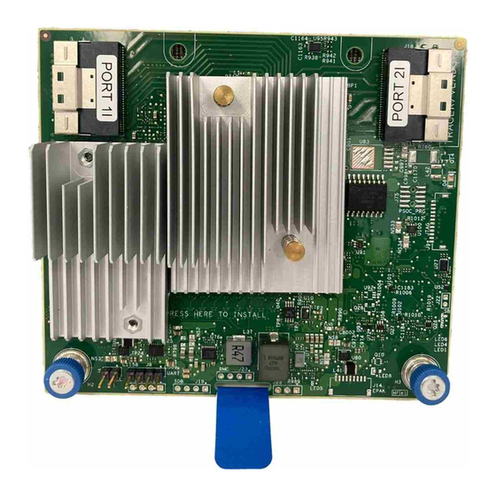
HPE MR Gen10 Plus Controller HPE MR Gen10 Plus Controller Figure 4: MR216i-p components Figure 4: MR216i-p components Item Item Description Description Internal x8 SlimSAS Connector, Port 1i Internal x8 SlimSAS Connector, Port 2i Figure 5: MR416i-p components Figure 5: MR416i-p components... - Page 162 Item Item Description Description Internal x8 SlimSAS Connector, Port 1i Internal x8 SlimSAS Connector, Port 2i HPE MR Gen10 Plus Controller...
-
Page 163: Energy Pack Options
Energy pack options Energy pack options Hewlett Packard Enterprise offers two centralized backup power source options to back up write cache content on the controllers in case of an unplanned server power outage. HPE Smart Storage Battery HPE Smart Storage Hybrid Capacitor IMPORTANT: IMPORTANT: The HPE Smart Storage Hybrid Capacitor is only supported on Gen10 and later servers. -
Page 164: Hpe Smart Storage Battery
HPE Smart Storage Battery Smart Storage Battery The HPE Smart Storage Battery supports the following devices: HPE Smart Array SR controllers HPE Smart Array MR controllers After the battery is installed, it might take up to two hours to charge. Controller features requiring backup power are not re-enabled until the battery is capable of supporting the backup power. -
Page 165: Hpe Smart Storage Hybrid Capacitor
HPE Smart Storage Hybrid Capacitor HPE Smart Storage Hybrid Capacitor The HPE Smart Storage Hybrid Capacitor supports the following devices: HPE SR controllers HPE MR controllers The capacitor pack can support up to two devices. Before installing the HPE Smart Storage Hybrid Capacitor, verify that the system BIOS meets the minimum firmware requirements to support the capacitor pack. -
Page 166: Energy Pack Specifications
Energy pack specifications Energy pack specifications Table 1: HPE Smart Storage Battery (96W) Table 1: HPE Smart Storage Battery (96W) Feature Feature Description Description Time required to 96 W: 2 hours (For maximum load of 24 devices) recharge Smart Storage Battery Duration of Smart 150 seconds (maximum support) -
Page 167: Specifications
Specifications Specifications For more information on cable, power, environmental, compliance, and general specifications, see the HPE Compute Transceiver and HPE Compute Transceiver and Cable Hardware Matrix. Cable Hardware Matrix Specifications... -
Page 168: Memory And Storage Capacity Conventions
Memory and storage capacity conventions Memory and storage capacity conventions Memory capacities are specified using binary prefixes: KiB = 2 bytes MiB = 2 bytes GiB = 2 bytes TiB = 2 bytes Storage capacities are specified using SI prefixes: KB = 10 bytes MB = 10 bytes GB = 10 bytes... -
Page 169: Raid Conventions
RAID conventions RAID conventions Hewlett Packard Enterprise uses the following naming convention for RAID levels: RAID 0 RAID 1 RAID 10 RAID 5 RAID 50 RAID 6 RAID 60 RAID 50 and RAID 60 are also known in the industry as RAID 5+0 and RAID 6+0, respectively. RAID conventions... -
Page 170: Controller Specifications
Controller specifications Controller specifications For more information about the specifications for the controller, see QuickSpecs QuickSpecs. Controller specifications... -
Page 171: Websites
Websites Websites General websites General websites Single Point of Connectivity Knowledge (SPOCK) Storage compatibility matrix https://www.hpe.com/storage/spock https://www.hpe.com/storage/spock Storage white papers and analyst reports https://www.hpe.com/storage/whitepapers https://www.hpe.com/storage/whitepapers For additional websites, see Support and other resources. Websites... -
Page 172: Support And Other Resources
Support and other resources Support and other resources Support and other resources... -
Page 173: Accessing Hewlett Packard Enterprise Support
Accessing Hewlett Packard Enterprise Support Accessing Hewlett Packard Enterprise Support For live assistance, go to the Contact Hewlett Packard Enterprise Worldwide website: https://www.hpe.com/info/assistance https://www.hpe.com/info/assistance To access documentation and support services, go to the Hewlett Packard Enterprise Support Center website: https://www.hpe.com/support/hpesc https://www.hpe.com/support/hpesc Information to collect Information to collect... -
Page 174: Accessing Updates
Accessing updates Accessing updates Some software products provide a mechanism for accessing software updates through the product interface. Review your product documentation to identify the recommended software update method. To download product updates: Hewlett Packard Enterprise Support Center https://www.hpe.com/support/hpesc https://www.hpe.com/support/hpesc Hewlett Packard Enterprise Support Center: Software downloads https://www.hpe.com/support/downloads https://www.hpe.com/support/downloads... -
Page 175: Remote Support
Remote support Remote support Remote support is available with supported devices as part of your warranty or contractual support agreement. It provides intelligent event diagnosis, and automatic, secure submission of hardware event notifications to Hewlett Packard Enterprise, which initiates a fast and accurate resolution based on the service level of your product. -
Page 176: Customer Self Repair
Customer self repair Customer self repair Hewlett Packard Enterprise customer self repair (CSR) programs allow you to repair your product. If a CSR part needs to be replaced, it will be shipped directly to you so that you can install it at your convenience. Some parts do not qualify for CSR. Your Hewlett Packard Enterprise authorized service provider will determine whether a repair can be accomplished by CSR. -
Page 177: Warranty Information
Warranty information Warranty information To view the warranty information for your product, see the links provided below: HPE ProLiant and IA-32 Servers and Options https://www.hpe.com/support/ProLiantServers-Warranties https://www.hpe.com/support/ProLiantServers-Warranties HPE Enterprise and Cloudline Servers https://www.hpe.com/support/EnterpriseServers-Warranties https://www.hpe.com/support/EnterpriseServers-Warranties HPE Storage Products https://www.hpe.com/support/Storage-Warranties https://www.hpe.com/support/Storage-Warranties HPE Networking Products https://www.hpe.com/support/Networking-Warranties https://www.hpe.com/support/Networking-Warranties Warranty information... -
Page 178: Regulatory Information
Regulatory information Regulatory information To view the regulatory information for your product, view the Safety and Compliance Information for Server, Storage, Power, Networking, and Rack Products, available at the Hewlett Packard Enterprise Support Center: https://www.hpe.com/support/Safety-Compliance-EnterpriseProducts https://www.hpe.com/support/Safety-Compliance-EnterpriseProducts Additional regulatory information Additional regulatory information Hewlett Packard Enterprise is committed to providing our customers with information about the chemical substances in our products as needed to comply with legal requirements such as REACH (Regulation EC No 1907/2006 of the European Parliament and the Council). -
Page 179: Documentation Feedback
Documentation feedback Documentation feedback Hewlett Packard Enterprise is committed to providing documentation that meets your needs. To help us improve the documentation, use the Feedback button and icons (located at the bottom of an opened document) on the Hewlett Packard Enterprise Support Center portal (https://www.hpe.com/support/hpesc https://www.hpe.com/support/hpesc) to send any errors, suggestions, or comments.