
Related Manuals for Mitsubishi Electric MR-J5-B


Summary of Contents for Mitsubishi Electric MR-J5-B
- Page 1 Mitsubishi Electric AC Servo System MR-J5-B/MR-J5W-B User's Manual (Introduction) -MR-J5-_B_ -MR-J5W_-_B_...
-
Page 3: Safety Instructions
SAFETY INSTRUCTIONS Please read the instructions carefully before using the equipment. To use the equipment correctly, do not attempt to install, operate, maintain, or inspect the equipment until you have read through this manual, installation guide, and appended documents carefully. Do not use the equipment until you have a full knowledge of the equipment, safety information and instructions. - Page 4 [Installation/wiring] WARNING ● To prevent an electric shock, turn off the power and wait for 15 minutes or more before starting wiring and/or inspection. ● To prevent an electric shock, ground the servo amplifier. ● To prevent an electric shock, any person who is involved in wiring should be fully competent to do the work.
-
Page 5: Disposal Of Waste
Please dispose of this product, battery (primary battery), and other options according to your local laws and regulations. ABOUT THE MANUAL e-Manuals are Mitsubishi Electric FA electronic book manuals that can be browsed with a dedicated tool. e-Manuals enable the following: •... -
Page 6: U.s. Customary Units
Interpreting servo parameter numbers For a servo parameter which uses one particular digit to select a function, the position of its digit indicates the detail number of the servo parameter, and the value in hexadecimal which is set to the digit indicates the selected function. For example, the detail number of the servo parameter in the last digit is expressed as [Pr. -
Page 7: Table Of Contents
CONTENTS SAFETY INSTRUCTIONS..............1 DISPOSAL OF WASTE . - Page 8 Output signal (DO) forced output............. 60 Servo amplifier setting initialization .
-
Page 9: Chapter 1 Specifications
SPECIFICATIONS Outline The MR-J5_-_B_ is a servo amplifier that supports SSCNET III/H communication. One MR-J5W_-_B servo amplifier can drive two or three servo motors. The footprint of one MR-J5W_-_B servo amplifier is considerably smaller than that of two or three MR-J5-_B_ servo amplifiers. Model designation Rating plate The following shows an example of the rating plate for explanation of each item. - Page 10 Model The following describes what each block of a model name indicates. Not all combinations of the symbols are available. ■MR-J5-_B_ M R - - 6 0 B Special specification Series Symbol Special specification Rated output None Standard Symbol Rated output [kW] Load-side encoder A/B/Z-phase input compatible Standard model without the dynamic brake MR-J5-_B-RJ without the dynamic brake...
-
Page 11: Servo Amplifier/Motor Combinations
■MR-J5W_-_B M R - J 5 W 2 4 4 B Special specification Series Symbol Special specification Number of axes None Standard Number Symbol of axes Without the dynamic brake SSCNET III/H interface Rated output Rated output [kW] Symbol A-axis B-axis C-axis 0.75... -
Page 12: Servo Amplifier Standard Specifications
MR-J5-_B Mitsubishi Electric high-speed serial communication interface MR-J5-_B-RJ Mitsubishi Electric high-speed serial communication/A/B/Z-phase differential input signal Protective functions Overcurrent shut-off, regenerative overvoltage shut-off, overload shut-off (electronic thermal), servo motor overheat protection, encoder error protection, regenerative error protection, undervoltage protection, instantaneous power failure protection, overspeed protection, excessive error protection,... - Page 13 Model: MR-J5- 100B 200B 350B 500B 700B Satisfied standards CE marking LVD: EN 61800-5-1, EMC: EN 61800-3, MD: EN ISO 13849-1:2015, EN 61800-5-2, EN 62061 UKCA marking LVD: BS EN 61800-5-1, EMC: BS EN IEC 61800-3, MD: BS EN ISO 13849-1:2015, BS EN 61800-5-2, BS EN 62061 UL standard UL 61800-5-1...
- Page 14 MR-J5-_B4 Mitsubishi Electric high-speed serial communication interface MR-J5-_B4-RJ Mitsubishi Electric high-speed serial communication/A/B/Z-phase differential input signal Protective functions Overcurrent shut-off, regenerative overvoltage shut-off, overload shut-off (electronic thermal), servo motor overheat protection, encoder error protection, regenerative error protection, undervoltage protection, instantaneous power failure protection, overspeed protection, excessive error protection,...
-
Page 15: Mr-J5W2-_B
Supported Scale measurement function Supported Load-side encoder interface Mitsubishi Electric high-speed serial communication Protective functions Overcurrent shut-off, regenerative overvoltage shut-off, overload shut-off (electronic thermal), servo motor overheat protection, encoder error protection, regenerative error protection, undervoltage protection, instantaneous power failure protection, overspeed protection, excessive error protection,... - Page 16 *1 This value is applicable when all I/O signals are used. Reducing the number of I/O points decreases the current capacity. *2 If closely mounting the servo amplifiers, operate them at an ambient temperature of 0 ˚C to 45 ˚C or at 75 % or less of the effective load ratio.
-
Page 17: Mr-J5W3-_B
MR-J5W3-_B Model: MR-J5W3- 222B 444B Output Voltage 3-phase 0 V AC to 240 V AC Rated current (each axis) Main circuit power Voltage/ At AC 3-phase or 1-phase 200 V AC to 240 V AC, 50 Hz/60 Hz supply input Frequency input At DC... - Page 18 *1 This value is applicable when all I/O signals are used. Reducing the number of I/O points decreases the current capacity. *2 If closely mounting the servo amplifiers, operate them at an ambient temperature of 0 ˚C to 45 ˚C or at 75 % or less of the effective load ratio.
-
Page 19: Functional Safety
Functional safety Item Specifications Safety sub-function STO (IEC/EN 61800-5-2) Safety Satisfied standards EN ISO 13849-1:2015 Category 3 PL e, IEC 61508 SIL 3, EN 62061 SIL CL 3, EN 61800-5-2 performance Response performance 8 ms or less (STO input off → energy shut off) Test pulse input (STO) Test pulse interval: 1 Hz to 25 Hz, test pulse off time: Up to 1 ms Mean time to dangerous failure... -
Page 20: Function Block Diagram
Function block diagram The following shows the function block diagram of this servo amplifier. MR-J5-_B_ 200 V class Power factor improving Regenerative DC reactor option Servo amplifier Servo motor Diode stack Dynamic brake Relay circuit MCCB Current Power detector supply Regenerative Charge light... - Page 21 400 V class Power factor improving Regenerative DC reactor option Servo amplifier Servo motor Diode stack Dynamic brake Relay circuit MCCB Current Power detector supply Regenerative Charge light Cooling fan Electromagnetic brake Control 24 V DC circuit power supply circuit switch Encoder Base...
-
Page 22: Mr-J5W_-_B
MR-J5W_-_B The following is an example using MR-J5W3-_B. Regenerative option P+ C CNP1 CNP2 Diode Built-in stack regenerative A-axis Relay TRM (A) resistor servo motor MCCB Regenerative Power Current A-axis supply detector output Charge Dynamic light brake circuit A Cooling fan A-axis STO circuit Control... -
Page 23: Configuration Including Peripheral Equipment
Configuration including peripheral equipment • To prevent a malfunction, do not connect these connectors to any network other than the specified network. • Equipment other than the servo amplifier and servo motor is optional or a recommended product. The following is an example using MR-J5-20B-RJ. R S T Power supply CN1A... -
Page 24: Special Specifications
Special specifications Servo amplifiers without the dynamic brake (-ED/-RU) Summary This section describes the servo amplifiers without the dynamic brake. Items not described in this section are the same as the MR-J5-_B(4)(-RJ) and MR-J5W_-_B. Specifications The built-in dynamic brakes of the servo amplifiers with capacity of 7 kW or less are removed. Take safety measures such as providing an extra circuit in case of an emergency stop, alarm, and servo motor stop at power supply shut-off. -
Page 25: Chapter 2 Function
FUNCTION Function list The function list of this servo amplifier is shown in the following table. For details of the functions, refer to each section indicated in the detailed explanation field. Control mode Functions Detailed functions Description Ver. Detailed explanation Control mode Position control mode (P_SSC) This function operates the servo motor in the... - Page 26 Position detection Functions Detailed functions Description Ver. Detailed explanation Control method Semi closed loop system This function uses the servo motor encoder to configure semi closed loop systems. Fully closed loop system This function uses the load-side encoder to Refer to "USING A FULLY CLOSED configure fully closed loop systems.
- Page 27 Control function Functions Detailed functions Description Ver. Detailed explanation Vibration Advanced vibration suppression This function suppresses vibration and residual Refer to "Advanced vibration suppression control II vibration at an arm end. suppression control II" in the following manual. MR-J5 User's Manual (Adjustment) Machine resonance suppression This function decreases the gain of the specific...
- Page 28 Adjustment function Functions Detailed functions Description Ver. Detailed explanation Automatic Quick tuning This function automatically adjusts the gain at Refer to "Quick tuning" in the adjustment servo-on in a short time without acceleration/ following manual. deceleration operation of the servo motor. MR-J5 User's Manual Response without overshoot is possible, saving (Adjustment)
- Page 29 I/O, monitor Functions Detailed functions Description Ver. Detailed explanation DI/DO Output signal selection (device This function assigns output devices such as Refer to "Assigning I/O devices" in setting) MBR (Electromagnetic brake interlock) to the following manual. certain pins of the connector. MR-J5 User's Manual (Function) Page 60 Output signal (DO) Output signal (DO) forced output...
- Page 30 Protective functions Functions Detailed functions Description Ver. Detailed explanation Alarm Alarm function This function displays an alarm or warning when Refer to "Alarm function" in the an error occurs during operation. When an following manual. alarm occurs, ALM (Malfunction) turns off and MR-J5 User's Manual (Function) stops the servo motor.
- Page 31 Diagnostics Functions Detailed functions Description Ver. Detailed explanation Drive data diagnosis Drive recorder This function continuously monitors the servo Refer to "Drive recorder" in the status and records the state transition before following manual. and after an alarm for a fixed period of time. The MR-J5 User's Manual (Function) recorded data can be checked by the Waveform-Display button on the drive recorder...
-
Page 32: Security
Security To completely prevent unauthorized access to the system from external devices, the user also must take safety measures. Mitsubishi Electric Corporation cannot be held responsible for any problems caused by unauthorized access. 2 FUNCTION 2.2 Security... -
Page 33: Chapter 3 Structure
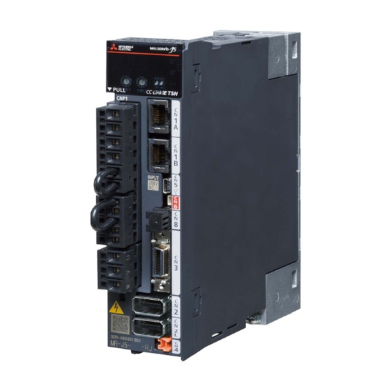
STRUCTURE Parts identification MR-J5-_B_ The diagram shows the MR-J5-10B-RJ. Inside of the display cover SFTY (14) Side (15) (16) (10) (11) (17) (12) (13) (18) (19) Bottom Name Application Detailed explanation Page 35 Switch setting and Display section The 3-digit, 7-segment LED display shows the servo status and alarm number. - Page 34 Name Application Detailed explanation (10) I/O signal connector (CN3) Connect the digital I/O signals. Refer to "Connectors and pin The analog monitor is output from this connector. assignments" in the following manual. MR-J5 User's Manual (Hardware) (11) Encoder connector (CN2) Connect a servo motor encoder or an external encoder.
- Page 35 MR-J5W_-_B Inside of the display cover (10) SFTY (12) (14) (13) (21) Side (15) (16) (17) (18) (19) (20) (11) Name Application Detailed explanation Page 35 Switch setting and Display section The 3-digit, 7-segment LED display shows the servo status and alarm number.
- Page 36 Name Application Detailed explanation (15) Functional safety I/O signal connector Connect an external safety relay to use the STO function. Refer to "USING STO (CN8) FUNCTION" and "USING FUNCTIONAL SAFETY" in the following manual. MR-J5 User's Manual (Hardware) (16) I/O signal connector (CN3) Connect the digital I/O signals.
-
Page 37: Switch Setting And Display Of The Servo Amplifier
Switch setting and display of the servo amplifier Switching to the test operation mode and configuring network setting can be done with switches on the servo amplifier. The network communication status and alarm status can also be checked on the display (3-digit, 7-segment LED) of the servo amplifier. - Page 38 Test operation select switch (SW3-1) When the test operation mode is selected with the test operation select switch (SW3-1), the SSCNET III/H communication for the servo amplifier and later shuts off. Turning "ON (up)" the test operation select switch enables the test operation mode. In the test operation mode, functions such as JOG operation, positioning operation, and machine analyzer are available using MR Configurator2.
- Page 39 Rotary switch settings Control axis No. 23-axis 24-axis 25-axis 26-axis 27-axis 28-axis 29-axis 30-axis 31-axis 32-axis 33-axis 34-axis 35-axis 36-axis 37-axis 38-axis 39-axis 40-axis 41-axis 42-axis 43-axis 44-axis 45-axis 46-axis 47-axis 48-axis 49-axis 50-axis 51-axis 52-axis 53-axis 54-axis 55-axis 56-axis 57-axis 58-axis 59-axis...
- Page 40 ■For multi-axis servo amplifiers Rotary switch settings Control axis No. A-axis B-axis C-axis 1-axis 2-axis 3-axis 2-axis 3-axis 4-axis 3-axis 4-axis 5-axis 4-axis 5-axis 6-axis 5-axis 6-axis 7-axis 6-axis 7-axis 8-axis 7-axis 8-axis 9-axis 8-axis 9-axis 10-axis 9-axis 10-axis 11-axis 10-axis 11-axis 12-axis...
- Page 41 Rotary switch settings Control axis No. A-axis B-axis C-axis 51-axis 52-axis 53-axis 52-axis 53-axis 54-axis 53-axis 54-axis 55-axis 54-axis 55-axis 56-axis 55-axis 56-axis 57-axis 56-axis 57-axis 58-axis 57-axis 58-axis 59-axis 58-axis 59-axis 60-axis 59-axis 60-axis 61-axis 60-axis 61-axis 62-axis 61-axis 62-axis 63-axis 62-axis...
-
Page 42: 7-Segment Led
7-segment LED The network connection status, servo status, and alarm/warning occurrence statuses can be checked on the 7-segment LED display. Display sequence The following shows the display sequence of the 7-segment LED display after power-on. Once a system check is complete and the servo amplifier is started, the network connection status will be displayed. - Page 43 Alarm display When an alarm/warning occurs, the alarm status is displayed. This is an example of the alarm display for when [AL. 032.2 Overcurrent] is occurring. ■1-axis servo amplifier Status display Alarm No. Alarm detail Blank After 0.6 s After 0.6 s After 0.6 s Alarm No.
- Page 44 When the network is connected The network connection status is displayed as follows. The status of all axes is displayed with scrolling display. The last two digits display the axis No. in decimal. Ready-off Servo-on (ready-on) Servo-on ■1-axis servo amplifier Status display Blank After 1.8 s...
- Page 45 When the network is not connected The 7-segment LED display during initialization is as follows. Display Status Description Initializing • The power of the servo amplifier was switched on when the power of the controller was off. • The axis No. set by the rotary switches (SW1/SW2) of the servo amplifier and the axis No.
-
Page 46: Status Leds
Other status displays Display Status Description Test operation mode Test operation mode, output signal (DO) forced output, or motor-less operation was set. The last two digits display the axis No. in decimal. CPU error Indicates that a CPU watchdog error has occurred. Initialization in progress Indicates that initialization of settings such as parameters is in progress. -
Page 47: Chapter 4 Startup
STARTUP • MR-J5_-_B_ servo amplifiers can be set with MR Configurator2 with software version 1.130L or later. • This chapter explains how to start up the servo amplifier by using MR Configurator2 with software version 1.100E. • Before starting operation, check each servo parameter. Depending on the machine, an unexpected operation may occur. - Page 48 Start MR Configurator2 and create a new project. For the connection setting, select USB. Select the servo amplifier model. Selecting "Parameter" from the project tree opens the "Parameter Setting" screen. 4 STARTUP...
- Page 49 Select a group of servo parameters in the selection tree of the "Parameter Setting" window to display and configure the settings. After changing the servo parameter, click "Selected Items Write" or "Axis Writing". 4 STARTUP...
- Page 50 Abbreviated servo parameters prefixed with * and servo parameters marked with ** are enabled after the power is cycled or a software reset is performed. Click "Software Reset" in MR Configurator2 to perform the software reset. 4 STARTUP...
-
Page 51: Turning On Servo Amplifier For The First Time
Turning on servo amplifier for the first time • For the controller settings, refer to the relevant controller manual. • For the gain adjustment, refer to the following manual. MR-J5 User's Manual (Adjustment) When turning on the servo amplifier for the first time, follow the steps below. Procedure Description Reference... -
Page 52: Test Operation Of The Servo Motor Alone In Test Operation Mode
Test operation of the servo motor alone in test operation mode • If the servo motor operates in an unintended manner, stop the servo motor with EM2 (Forced stop 2). Check that the servo amplifier and servo motor operate normally. With the servo motor disconnected from the machine, use the test operation mode and check whether the servo motor operates correctly. -
Page 53: Equipment Configuration Setting
To operate the servo motor, input the motor speed and acceleration/deceleration time constants, then click "Forward CCW" or "Reverse CW". The servo motor operates only while the button is being clicked. Give a low speed command at first and check the operation status. After the test operation is complete, turn off the power and "OFF (down)"... -
Page 54: Operation By Controller Command
Operation by controller command Confirm that the servo motor operates correctly under the commands from the controller. Give a low speed command at first to check the servo motor operations such as the rotation direction. If the servo motor does not operate in the intended direction, check the input signal. -
Page 55: Instructions On Startup
Instructions on startup Instructions for power-on • When the absolute position detection system is used in a rotary servo motor, [AL. 025 Absolute position erased] occurs the first time that the power is turned on and the servo motor cannot be changed to servo-on status. Shut off the power once, then cycle the power to deactivate the alarm. -
Page 56: Duplicate Setting
Duplicate setting Servo amplifier parameters for which setting has been completed can be copied to another servo amplifier. Use this function when replacing the servo amplifier of equipment with another servo amplifier during operation, and when starting up multiple devices with the same configuration. Restrictions ■The following data is not duplicated. -
Page 57: Test Operation Mode
Test operation mode • For a multi-axis servo amplifier, all axes are switched to the test operation mode simultaneously. However, the test operation can actually be executed on only one of the A, B, or C-axis. • When the test operation mode is selected with the test operation select switch (SW3-1), the SSCNET III/H communication for the servo amplifier and later shuts off. -
Page 58: Motor Driving By Test Operation
Motor driving by test operation JOG operation The JOG operation can be performed when there is no command from the controller. The motor can be operated at the specified speed. Operate the motor using the JOG Mode screen of MR Configurator2. ■Motor operation setting (1) Set the motor speed and acceleration/deceleration time constants for JOG operation. - Page 59 Positioning operation Positioning operation can be performed without the controller. Operate the motor using the Positioning Mode screen of MR Configurator2. ■Motor operation setting (1) Set the motor speed, acceleration/deceleration time constants, and travel distance in the positioning operation mode. When changing the speed to the permissible speed, set the speed in [Pr.
- Page 60 Program operation Positioning operation using multiple operation patterns can be performed without a controller. Operate the motor using the Program Operation screen of MR Configurator2. For details, refer to Help of MR Configurator2. Open the Program Operation screen of MR Configurator2. Item Screen operation Program display...
-
Page 61: Motor-Less Operation
Motor-less operation • The motor-less operation cannot be used in the fully closed loop control mode, linear servo motor control mode or direct drive motor control mode. Without connecting a servo motor to the servo amplifier, output signals or status displays can be provided in response to the controller commands as if the servo motor is actually running. -
Page 62: Output Signal (Do) Forced Output
Output signal (DO) forced output This function forcibly switches the output signals on and off regardless of the servo status. Use this function for purposes such as checking output signal wiring. Operate this function on the DO Forced Output screen of MR Configurator2. Each output signal can be turned on/off by clicking the ON/OFF button next to its name. -
Page 63: Servo Amplifier Setting Initialization
Servo amplifier setting initialization Servo amplifier settings can be initialized by using the engineering tool (MR Mode Change packed with MR Configurator2). However, information related to the servo amplifier, including power-on cumulative time and the number of relays on/off, is not initialized. -
Page 64: Chapter 5 Maintenance, Inspection And Parts Replacement
MAINTENANCE, INSPECTION AND PARTS REPLACEMENT Inspection items Precautions • Do not disassemble, repair, or modify the product. • For repair and parts replacement, contact your local sales office. • To prevent a malfunction, do not perform an insulation resistance test (megger test) on the servo amplifier. Periodic inspection Perform the following inspections. -
Page 65: Parts With A Service Life
Parts with a service life The service life of the following parts is listed below. In addition, the service life varies depending on the operating methods and environment. If any fault is found in a part, it is necessary to replace it immediately regardless of its service life. For parts replacement, please contact your local sales office. -
Page 66: Replacing Fan Unit
Replacing fan unit The internal circuits of the servo amplifier may be damaged by static electricity. Take the following precautions. • Ensure that the work bench and your body are grounded. • Do not directly touch conductive areas such as the connector pins and electrical parts. The fan unit is composed of a cooling fan and its cover. -
Page 67: Chapter 6 Compliance With Global Standards
COMPLIANCE WITH GLOBAL STANDARDS This chapter provides information common among AC servo amplifiers. Information that is not applicable to MR-J5 servo amplifier/other equipment combinations is also included. Compliance with global standards For compliance with the standards of Europe/UK, United States/Canada, and South Korea, refer to the following manual. Safety Instructions and Precautions for MR-J5 AC Servos (IB(NA)-0300391) Handling of AC servo amplifier batteries for the United Nations Recommendations on the... -
Page 68: Purpose
Purpose To enable safer transportation of lithium metal batteries. Handling during transportation This section describes how to handle lithium metal batteries in transportation. The batteries alone transported by air are classified as UN3090, and the batteries packed with or contained in equipment transported by air are classified as UN3091. Lithium metal batteries are classified as SP188 when transported by sea as non-dangerous goods. -
Page 69: Package At Our Shipment
For maritime or air transportation, the lithium battery mark (Figure 1) is required also for the outer package containing several packages of Mitsubishi Electric cells or batteries. When the content of a package must be handled as dangerous goods (Class 9), the package must comply with UN specification packaging requirements. -
Page 70: Symbol For The New Eu Battery Directive
• This mark is valid only in EU. This mark is in accordance with directive 2006/66/EC Article 20 "Information for end-users" and Annex . MITSUBISHI ELECTRIC products are designed and manufactured with high quality materials and components which can be recycled and/or reused. -
Page 71: Compliance With China Compulsory Certification (Ccc)
Some products are required to comply with China Compulsory Certification (hereinafter referred to as CCC) if exported, distributed, or sold to China. An outline of CCC is explained in this section. Mitsubishi Electric servo products are not subject to CCC. -
Page 72: Compliance With The China Rohs Directive
Compliance with the China RoHS directive Outline The China RoHS directive: (Management Methods for Controlling Pollution by Electronic 电子信息产品污染控制管理办法 Information Products) came into effect on March 1, 2007. The China RoHS directive was replaced by the following China RoHS directive: (Management Methods for the Restriction of the Use of 电器电子产品有害物质限制使用管理办法... - Page 73 Difference between the China RoHS directive and the EU RoHS directive The China RoHS directive allows no restriction exemption unlike the EU RoHS directive. Although a product complies with the EU RoHS directive, a hazardous substance in the product may be considered to be above the limit requirement (marked "") in the China RoHS directive.
-
Page 74: Revisions
First edition This manual confers no industrial property rights or any rights of any other kind, nor does it confer any patent licenses. Mitsubishi Electric Corporation cannot be held responsible for any problems involving industrial property rights which may occur as a result of using the contents noted in this manual. -
Page 75: Warranty
We will review the acceptability of the abovementioned applications, if you agree not to require a specific quality for a specific application. Please contact us for consultation. (3) Mitsubishi Electric shall have no responsibility or liability for any problems involving programmable controller trouble and system trouble caused by DoS attacks, unauthorized access, computer viruses, and other cyberattacks. -
Page 76: Trademarks
TRADEMARKS MELSERVO is a trademark or registered trademark of Mitsubishi Electric Corporation in Japan and/or other countries. All other product names and company names are trademarks or registered trademarks of their respective companies. IB(NA)-0300578ENG-A... - Page 78 IB(NA)-0300578ENG-A(2207)MEE MODEL: MODEL CODE: HEAD OFFICE : TOKYO BUILDING, 2-7-3 MARUNOUCHI, CHIYODA-KU, TOKYO 100-8310, JAPAN NAGOYA WORKS : 1-14 , YADA-MINAMI 5-CHOME , HIGASHI-KU, NAGOYA , JAPAN When exported from Japan, this manual does not require application to the Ministry of Economy, Trade and Industry for service transaction permission. Specifications are subject to change without notice.