Table of Contents
Advertisement
Quick Links
TABLE OF CONTENTS
1 Service Navigation ----------------------------------------------- 2
MAX700PHK)----------------------------------------------- 2
1.2. Speakers Setup -------------------------------------------- 2
2 Specifications ----------------------------------------------------- 3
3 Disassembly and Assembly Instructions ---------------- 4
3.2. Disassembly of Tweeter Speaker (SP1) ------------- 7
3.3. Disassembly of Full Range Speaker (SP4) --------- 7
3.4. Disassembly of Full Range Speaker (SP3) --------- 8
3.6. Disassembly of Woofer Speaker (SP2) ------------- 11
Assembly ---------------------------------------------------12
(For SB-MAX700PHK) ---------------------------------14
(For SB-MAX700PHK) ---------------------------------15
4 Wiring Connection Diagram ---------------------------------16
4.1. Front Speakers (SB-MAX700PHK) ------------------16
5 Exploded View and Replacement Parts List -----------17
P.C.B.
Model No.
Product Color : (K)... Black Type
PAGE
Parts Location -------------------------------------------- 17
5.2. Packaging-------------------------------------------------- 18
5.3. Replacement Parts List--------------------------------- 19
© Panasonic Corporation 2013, All rights reserved.
Unauthorized copying and distribution is a violation of
law.
Speaker System
SB-MAX700PH
SB-MAX700GS
PSG1301011CE
PAGE
Advertisement
Table of Contents

Related Manuals for Panasonic SB-MAX700PH


Summary of Contents for Panasonic SB-MAX700PH
-
Page 1: Table Of Contents
3.9. Replacement of Speaker Connector Housing (For SB-MAX700PHK) ---------------------------------15 4 Wiring Connection Diagram ---------------------------------16 4.1. Front Speakers (SB-MAX700PHK) ------------------16 5 Exploded View and Replacement Parts List -----------17 © Panasonic Corporation 2013, All rights reserved. Unauthorized copying and distribution is a violation of law. -
Page 2: Service Navigation
1 Service Navigation 1.1. Speaker System Information (SB-MAX700PHK) SB-MAX700PHK is use for the following models: SC-MAX700PHK SB-MAX700GSK is use for the following models: SC-MAX700GSK 1.2. Speakers Setup... -
Page 3: Specifications
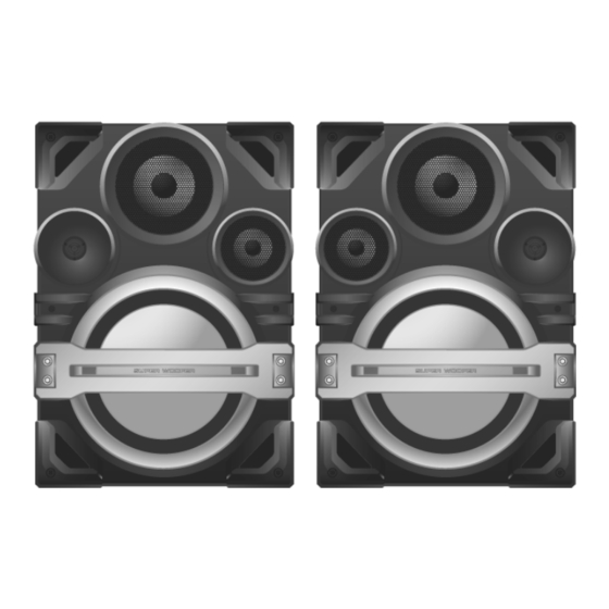
2 Specifications Front Speakers Type 4 way, 4 speaker system (Bass reflex) Speaker(s) Super Woofer (Low) 38 cm cone type Super Woofer (Medium Low) 20 cm cone type Woofer 10 cm cone type Tweeter 6 cm cone type 3 Ω (High), 3 Ω (Medium Low), Impedance 2 Ω... -
Page 4: Disassembly And Assembly Instructions
3 Disassembly and Assembly Instructions Caution Note: • This section describes procedures for checking the operation and replacing the main components. • For reassembly after operation checks or replacement, reverse the respective procedures. • Special reassembly procedures are described only when required. •... -
Page 5: Disassembly Of Upper Front Panel Assembly
3.1. Disassembly of Upper Front Step 3 : Remove 2 screws. Panel Assembly Step 1 : Remove 2 screws. Step 4 : Remove Corner Guard. Step 2 : Remove Corner Guard. - Page 6 Step 5 : Remove 2 screws. Step 7 : Detach the (+) and (-) speaker wires. Step 8 : Remove the Upper Front Panel Assembly. Step 6 : Insert two flathead screwdriver at the sides of the boss and apply light force to push out the Upper Front Panel Assem- bly by sequence (1-6) shown.
-
Page 7: Disassembly Of Tweeter Speaker (Sp1)
3.2. Disassembly Tweeter 3.3. Disassembly of Full Range Speaker (SP1) Speaker (SP4) • Refer to “Disassembly of Upper Front Panel Assembly”. • Refer to “Disassembly of Upper Front Panel Assembly”. Step 1 : Remove 2 screws. Step 1 : Remove 4 screws. Step 2 : Slightly lift up Full Range Speaker (SP4) as shown. -
Page 8: Disassembly Of Full Range Speaker (Sp3)
Step 4 : Remove the Full Range Speaker (SP4). 3.4. Disassembly of Full Range Speaker (SP3) • Refer to “Disassembly of Upper Front Panel Assembly”. Step 1 : Remove 4 screws. Step 2 : Slightly lift up Full Range Speaker (SP3) as shown. Step 3 : Detach the (+) and (-) speaker wires. -
Page 9: Disassembly Of Lower Front Panel Assembly
Step 4 : Remove the Full Range Speaker (SP3). 3.5. Disassembly of Lower Front Panel Assembly • Refer to “Disassembly of Upper Front Panel Assembly”. Step 1 : Remove 2 screws. Step 2 : Remove Corner Guard. - Page 10 Step 3 : Remove 2 screws. Step 5 : Remove 2 screws. Step 6 : Remove 2 screws. Step 4 : Remove Corner Guard. Step 7 : Detach the Lower Front Panel Assembly slightly as arrow shown. Caution : Do not exert strong force as it may damage the wiring within.
-
Page 11: Disassembly Of Woofer Speaker (Sp2)
Step 9 : Detach the 4P Wire Socket. 3.6. Disassembly Woofer Step 10 : Remove the Lower Front Panel Assembly. Speaker (SP2) • Refer to “Disassembly of Upper Front Panel Assembly”. • Refer to “Disassembly of Front Ornament Assembly”. Step 1 : Remove 8 screws. Step 2 : Slightly lift up Woofer Speaker (SP2) as shown. -
Page 12: Disassembly Of Lighting Wire
Step 4 : Remove the Woofer Speaker (SP2). 3.7. Disassembly of Lighting Wire P.C.B. Assembly • Refer to “Disassembly of Upper Front Panel Assembly”. • Refer to “Disassembly of Front Ornament Assembly”. Step 1 : Remove 14 screws. Step 2 : Remove 4 screws. - Page 13 Step 3 : Slightly lift up Front Ornament Assembly. Step 7 : Remove Lighting Wire P.C.B. Assembly. Step 4 : Release the 4P wire from the hole of Lower Front Panel Assembly. Caution : During assembling, inserted the 4P wire into the opening of Lower Front Panel Assembly as diagram shown.
-
Page 14: Replacement Of Speaker Connector Housing (For Sb-Max700Phk)
3.8. Replacement of Speaker Connector Housing (For SB-MAX700PHK) 3.8.1. Disassembly of Speaker Connector Housing Step 1: Insert a paper clip & push the Wire terminals outwards. Step 4: Insert the (-) speaker wire into the (-) hole of the Step 2: Detach the (+) and (-) speaker wire. speaker connector housing. -
Page 15: Replacement Of Speaker Connector Housing (For Sb-Max700Phk)
3.9. Replacement of Speaker Connector Housing (For SB-MAX700PHK) For Speaker wire connection, please refer to 1.2. Speaker setup 3.9.1. Disassembly of Speaker Connector Housing Step 4: Insert the (-) speaker wire into the (-) hole of the Step 1: Insert a paper clip & push the Wire terminals outwards. speaker connector housing. -
Page 16: Wiring Connection Diagram
4 Wiring Connection Diagram 4.1. Front Speakers (SB-MAX700PHK) -
Page 17: Exploded View And Replacement Parts List
5 Exploded View and Replacement Parts List 5.1. Front Speakers (SB-MAX700PHK) Cabinet Parts Location 14-1 14-2 (LIGHTING ZJ6110 P.C.B.) ZJ6109 ZJ6104 (LIGHTING P.C.B.) SB-MAX700GSK SB-MAX700PHK CABINET DRAWINGS... -
Page 18: Packaging
5.2. Packaging SB-MAX700GS/PH SB-MAX700GS/PH POLYFOAM (TOP) POLYFOAM (BOTTOM) SB-MAX700GSK SB-MAX700PHK PACKAGING DRAWINGS... -
Page 19: Replacement Parts List
5.3. Replacement Parts List 5.3.1. Front Speakers (SB-MAX700PH/ Safety Ref. No. Part No. Part Name & Qty Remarks Description GSK) 14-1 RFKVBVKX60-W 4P SPK CONNEC- TOR HOUSING WHITE (L) 14-1 RFKVBMAX700P 4P SPK CONNEC- Safety Ref. No. Part No. Part Name &... - Page 20 5.3.2. Packing Materials Safety Ref. No. Part No. Part Name & Qty Remarks Description PACKING MATERI- RPG0E40 PACKING CASE RPG0D55 PACKING CASE RPN2531 POLYFOAM RPF0643 MIRAMAT BAG IPSG1301...