Table of Contents
Advertisement
Quick Links
Colour Television
Contents
11. Styling Sheets
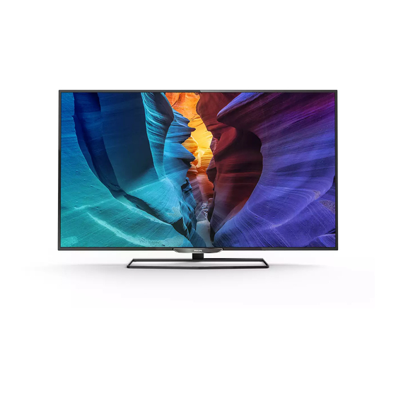
6600 series 49"
6600 series 55"
Published by XMM/SC 1543 Quality
©
2015
TP Vision Netherlands B.V.
All rights reserved. Specifications are subject to change without notice. Trademarks are the
property of Koninklijke Philips Electronics N.V. or their respective owners.
TP Vision Netherlands B.V. reserves the right to change products at any time without being obliged to adjust
earlier supplies accordingly.
PHILIPS and the PHILIPS' Shield Emblem are used under license from Koninklijke Philips Electronics N.V.
Page
Contents
2
2
5
9
9
10
13
16
17
23
27
Drawing PWB
28
32-33
34
46-47
48
49
50
51
52
53
54
55
56
57
58
59
Printed in the Netherlands
Chassis
TPS15.3A
Page
Subject to modification
EN 3122 785 19980
LA
Advertisement
Table of Contents

Related Manuals for Philips 49PUH6600/96


Summary of Contents for Philips 49PUH6600/96
-
Page 1: Table Of Contents
Koninklijke Philips Electronics N.V. or their respective owners. TP Vision Netherlands B.V. reserves the right to change products at any time without being obliged to adjust earlier supplies accordingly. PHILIPS and the PHILIPS’ Shield Emblem are used under license from Koninklijke Philips Electronics N.V. -
Page 2: Revision List
Notes: software & drivers. • Figures can deviate due to the different set executions. Table 2-1 Described Model Numbers and Diversity Block Mechanics Diagrams Schematics 49PUH6600/96 10.1 10.2 10.3 10.5 10.7 11.1 55PUH6600/96 10.1 10.2 10.4... - Page 3 Technical Specs, Diversity, and Connections TPS15.3A LA EN 3 Connections PC / DVI PC / DVI NETWORK 19900_001.eps Figure 2-1 Connection overview Note: The following connector colour abbreviations are used 5 - USB2 2.0 (acc. to DIN/IEC 757): Bk= Black, Bu= Blue, Gn= Green, Gy= Grey, Rd= Red, Wh= White, Ye= Yellow.
- Page 4 EN 4 TPS15.3A LA Technical Specs, Diversity, and Connections - Shield - n.c. - D2- Data channel - Ground - D1+ Data channel - Ground Red - Shield - Ground Green - D1- Data channel - Ground Blue - D0+ Data channel - +5V +5 V...
-
Page 5: Precautions, Notes, And Abbreviation List
Spare Parts the following points: • Route the wire trees correctly and fix them with the For the latest spare part overview, consult your Philips Spare mounted cable clamps. Part web portal. • Check the insulation of the Mains/AC Power lead for external damage. - Page 6 EN 6 TPS15.3A LA Precautions, Notes, and Abbreviation List result in sets which have the same CTN (Commercial Type 6 = play 16 : 9 format, 12 = play 4 : 3 Number; e.g. 28PW9515/12) but which have a different B.O.M. format number.
- Page 7 6.5 MHz. L' is Band (VESA standard for communication I, L is all bands except for Band I channel and display). Using E-DDC, LG.Philips LCD (supplier) the video source can read the EDID Loudspeaker information form the display.
- Page 8 SOPS Self Oscillating Power Supply Serial Peripheral Interface bus; a 4-wire synchronous serial data link standard S/PDIF Sony Philips Digital InterFace SRAM Static RAM Service Reference Protocol Small Signal Board Spread Spectrum Clocking, used to reduce the effects of EMI...
-
Page 9: Mechanical Instructions
Mechanical Instructions TPS15.3A LA EN 9 4. Mechanical Instructions Index of this chapter: Notes: 4.1 Cable Dressing • Figures below can deviate slightly from the actual situation, 4.2 Service Positions due to the different set executions. 4.3 Assembly/Panel Removal 4.4 Set Re-assembly Cable Dressing CN8101 ECN701... -
Page 10: Cable Dressing (55" 6600 Series)
Caution: Failure to follow these guidelines can seriously damage the display! Ensure that ESD safe measures are taken. Assembly/Panel Removal Instructions below apply to the 49PUH6600/96, but will be similar for 55" model. 4.3.1 Rear Cover Refer to Figure 4-3 for details. - Page 11 Mechanical Instructions TPS15.3A LA EN 11 M4 × 8 M3 × 8 M3 × 6 19980_102.eps Figure 4-3 Rear cover removal 4.3.2 Keyboard Control unit 1. Gently release the tapes that secure the keyboard cable. 2. Remove the fixation screws that secure the keyboard control panel.
- Page 12 EN 12 TPS15.3A LA Mechanical Instructions 4.3.5 Power Supply Unit (PSU) Caution: it is mandatory to remount all different screws at their original position during re-assembly. Failure to do so may result in damaging the PSU. 1. Unplug all connectors from the PSU. 2.
-
Page 13: Service Modes And Fault Finding
(Factory Mode). After entering the Factory mode, the following items are displayed, the Default value just for reference. Table 5-1 Factory mode overview Default value Item Item value 49PUH6600/96 55PUH6600/96 Description Brand Philips-TWN Philips-TWN Brand name... - Page 14 A description on how to upgrade the main check that what the current TV software: software can be found in the DFU or on the Philips website. 1. Press the “Menu” + “1999” + “Back” button on the remote control to enter the Factory mode.
- Page 15 Service Modes and Fault Finding TPS15.3A LA EN 15 5.4.5 Update the TV software • FUS_clustername_version.zip: Contains the “autorun.bin” which is needed to upgrade the TV main software and the software download application. 1. Turn the TV on and wait for it to boot completely. •...
-
Page 16: Alignments
EN 16 TPS15.3A LA Alignments 6. Alignments Index of this chapter: 6.1 General Alignment Conditions 6.2 Reset of Repaired SSB General Alignment Conditions Perform all electrical adjustments under the following conditions: , 50/ 60 3 Hz. • Power supply voltage: 90 - 264 V •... -
Page 17: Circuit Descriptions
Circuit Descriptions TPS15.3A LA EN 17 7. Circuit Descriptions Index of this chapter: Introduction 7.1 Introduction The TPS15.3A LA is a new chassis launched in AP in 2015. 7.2 Power Supply The whole range is covered by MSD8590QV. The major deltas 7.3 DC/DC Converters versus its predecessor support PAL/NTSC/SECAM, with 7.4 Front-End Analogue ATV reception and DVB-T reception... - Page 18 EN 18 TPS15.3A LA Circuit Descriptions 7.1.3 SSB Cell Layout DC/DC SPDIF Audio out Headphone DC/DC Tuner MSD8590QV-XZ HDMI HDMI NETWORK PC Audio ANALOG INPUT HDMI ANALOG I/O 19980_200.eps Figure 7-1 SSB layout cells (top view) (6600 series) back to 2015-Oct-23 div.table...
- Page 19 - direct-view LED with 2D-dimming: PSDL power board. replace a defective fuse with one with the correct specifications. This part is available in the regular market. Consult the Philips Service web portal for the order codes of the PSL stands for Power Supply with integrated LED-drivers. boards.
- Page 20 EN 20 TPS15.3A LA Circuit Descriptions DC/DC Converters • +TU_3V3, supply voltage for tuner The on-board DC/DC converters deliver the following voltages • USB_5V, input intermediate supply voltage for USB Power (depending on set execution): • 3V3_STB from the power supply for the scaler IC •...
- Page 21 Circuit Descriptions TPS15.3A LA EN 21 Main Board Power System P24V PANEL LED Driver AMP_24V For Audio Am plifier U601 AD83586 P12V Q403 AO4449-7A PANEL VB1 Pow er USB_5V For USB Port U703 G5312QN1U +5VSB 3V3_STB For MSD8590QV +5VSB U701 AP1117E33L-13-77 U401 MSD8590QV For SPI Flash U405 MX25L1606EM2I-12G...
- Page 22 EN 22 TPS15.3A LA Circuit Descriptions HDMI Video and Audio Processing - MSD8590QV Refer to figures 7-7 HDMI input configuration for the The MSD8590QV is the main audio and video processor (or application. System-on-Chip) for this platform. It has the following features: •...
-
Page 23: Ic Data Sheets
IC Data Sheets TPS15.3A LA EN 23 8. IC Data Sheets This chapter shows the internal block diagrams and pin configurations of ICs that are drawn as “black boxes” in the electrical diagrams (with the exception of “memory” and “logic” ICs). - Page 24 EN 24 TPS15.3A LA IC Data Sheets Diagram 10-2-9 Karaoke/MIC In/Audio Output B09, YSS952 (IC U603) Block diagram YSS952 Pinning information DVSS GPIO10 GPIO9 IOVDD YSS952 GPIO8 XOUT (QFN32) IOVDD (Top View) GPIO7 PLLVSS DVDD18 PLLVSS GPIO6 IC_N 19980_301.eps Figure 8-2 Internal block diagram and pin configuration back to 2015-Oct-23 div.table...
- Page 25 IC Data Sheets TPS15.3A LA EN 25 Diagram 10-2-9 Karaoke/MIC In/Audio Output B09, WM8524CGEDT/R (IC U604) Block diagram WM8524 Pinning information WM8524 19980_302.eps Figure 8-3 Internal block diagram and pin configuration back to 2015-Oct-23 div.table...
- Page 26 EN 26 TPS15.3A LA IC Data Sheets Diagram 10-2-12 Power B12, G5312QN1U (IC U703) Block diagram G5312QN1U On-Time On-Time PGOOD PGOOD Off-Time Off-Time DISCHG DISCHG controller controller PGND PGND 0.75V 0.75V Reference Reference ILIM ILIM AGND AGND Pinning information ILIM ILIM AGND AGND...
-
Page 27: Block Diagrams
Block Diagrams TPS15.3A LA EN 27 9. Block Diagrams Block diagram 6600 series Tuner LCD PANEL TDSH-T070F NOR FLASH ROM CVBS (Share with YPbPr Y) VIDEO MX25L1606EM2I-12G YPbPr YPbPr NAND FLASH ROM THGBMBG6D1KBAIL Hsync, Vsync DDR III x 2 TMDS HDMI 1 / DVI (4G 1866MHz) H5TQ4G63AFR-RDC... -
Page 28: Circuit Diagrams And Pwb Layouts
Circuit Diagrams and PWB Layouts TPS15.3A LA EN 28 10. Circuit Diagrams and PWB Layouts 10.1 A 715G6973 PSU 10-1-1 AC Input AC Input CN9903 NC / CONN F9901 FB9901 T5AH/250V BEAD SG9901 NC/DSPL-501N-A21F F9902 R9901 R9905 NR9903 NC/510k 1/2W 680K OHM +-1% 1/4W R9908 680K OHM +-1% 1/4W... - Page 29 Circuit Diagrams and PWB Layouts TPS15.3A LA EN 29 10-1-2 BD9801 KBP208G-C C9814 47PF L9801 220uH Vsin Vbus D9801 FMNS-1106S R9803 1MOHM +-1% 1/4W C9819 C9820 +VCC2 470PF C9816 C9803 C9804 HS9801 1uF 450V 1uF 450V C9811 C9810 HEAT SINK 100N 50V 10UF 50V R9804...
- Page 30 Circuit Diagrams and PWB Layouts TPS15.3A LA EN 30 10-1-3 Main power Main power T9101 12VS POWER X'FMR Vbus Q9103 L9101 NC/AOD4185 +12V_A C9106 2.2NF R9111 +VCC1 82K 2W R9147 D9108 R9110 330K +-1% 1/4W 1N4148 2R2 +-5% 1/4W R9118 L9102 NC/100K 1/8W 1% +12V...
- Page 31 Circuit Diagrams and PWB Layouts TPS15.3A LA EN 31 10-1-4 LED Driver LED Driver HS8101 VLED1 HEAT SINK CN8101 D8104 CONN SFF1005G R8101 +VLED 0.1R L8101 Vbus -VLED1 +VLED R8158 HS8102 0R05 1/4W T8101 HEAT SINK C8101 FB_LLC -VLED2 D8109 R8118 NC/FMX-23S +VLED...
- Page 32 Circuit Diagrams and PWB Layouts TPS15.3A LA EN 32 10-1-5 Power layout top GND2 GND4 CN8101 CN9102 L8101 J8112 D8105 J8124 U8105 J8119 J8122 HS8101 U8106 J8123 HS8102 HS8103 D8109 L9101 Q9102 C9113 D8104 J8117 L9102 J8116 HS9102 C9115 U8107 U8108 J9116 J8107...
- Page 33 Circuit Diagrams and PWB Layouts TPS15.3A LA EN 33 10-1-6 Power layout bottom SM12 R8160 R8158 R8133 C8121 R8156 R8172 C8126 R8165 R8134 C8143 R8168 R8169 C8145 C8129 C8130 C8127 C8128 JR9105 R9144 R8151 R8152 R9119 C8137 C8136 R9143 C9308 C9131 C8134 C8135...
-
Page 34: B 715G6546 Ssb
Circuit Diagrams and PWB Layouts TPS15.3A LA EN 34 10.2 B 715G6546 SSB 10-2-1 Tuner/VGA/Ethernet Inputs Tuner/VGA/Ethernet Inputs LG Silicon Tuner VCC_3V3 VCC_3V3 Place close to U401 RF Input TDSH-T070F VCC_3V3 (Side) FB101 Cable R101 R102 R103 R104 60R 0.6A TU_3V3 C132 C101... - Page 35 Circuit Diagrams and PWB Layouts TPS15.3A LA EN 35 10-2-2 AV/YPbPr/USB Inputs AV/YPbPr/USB Inputs AV Input (Share with Y) VCC_3V3 (Back) USB 2.0 Port For WiFi Module R141 PB_DET : Active HIGH USB trace run 90 Ohm differential pairs YPbPr Input (Internal) 4.7K1/16W space/trace/space/trace/space(mil)
- Page 36 Circuit Diagrams and PWB Layouts TPS15.3A LA EN 36 10-2-3 HDMI/MHL Inputs HDMI/MHL Inputs Run As 100 Ohm Differential Pairs space/trace/space/trace/space(mil) 12 / 8 / 5 / 8 / 12 CN501 HDMI U502 AZ1045-04F.R7G HDMI 2 Trace (mil) SHLD0 HDMI2_D2P TMDSD2+ HDMI2_CLKN 3102.81...
- Page 37 Circuit Diagrams and PWB Layouts TPS15.3A LA EN 37 10-2-4 MSD8590QV Inputs HDMI Input USB 2.0 Input U401D MSD8590QV Inputs HDMI1_D0N USB0_D- HDMI1_D0N RX0N DM_P0 USB0_D- HDMI1_D0P USB0_D+ HDMI1_D0P RX0P DP_P0 USB0_D+ HDMI1_D1N USB1_D- HDMI1_D1N USB1_D- RX1N DM_P1 HDMI1_D1P USB1_D+ HDMI1_D1P USB1_D+ RX1P...
- Page 38 R445 33 OHM 1/16W MSCL MSD8590QV-XZ 10,11,12,13 M_SCL R446 33 OHM 1/16W MSDA 10,11,12,13 M_SDA Only Philips project used. LED_RED LED_R Mode Select R448 NC/100OHM SPI Flash 3V3_STB CHIP_CONFIG[2:0] U405 should be programmed {PAD_PM_SPI_DI, PAD_PM_LED, PAD_PWM_PM} before soldering on PCB...
- Page 39 Circuit Diagrams and PWB Layouts TPS15.3A LA EN 39 10-2-6 MSD8560QV DDR III MSD8590QV DDR III 2nd DDR3 4G bit 1866MHz U401E DDR_1V5 A_DDR3_A0 B_DDR3_A0 RP401 RP402 A_DDR3_A[0] B_DDR3_A[0] A_DDR3_A1 B_DDR3_A1 A_DDR3_RASZ A-DDR3-RASZ B_DDR3_RASZ B-DDR3-RASZ A_DDR3_A[1] B_DDR3_A[1] A_DDR3_A2 B_DDR3_A2 A_DDR3_ODT A-DDR3-ODT B_DDR3_ODT B-DDR3-ODT...
- Page 40 Circuit Diagrams and PWB Layouts TPS15.3A LA EN 40 10-2-7 MSD8590QV Power/GND MSD8590QV Power/GND VCC_1V2 VCC_1V2_CPU DDR_1V5 VCC_3V3 3V3_STB C469 C470 C471 C472 C473 C474 C476 C477 C478 C479 C480 C4E1 C481 C482 C483 C484 C485 C486 C487 C488 C489 C490 C491 C492...
- Page 41 Circuit Diagrams and PWB Layouts TPS15.3A LA EN 41 10-2-8 Audio Amp/SPK/SPDIF Outputs Audio Amp/SPK/SPDIF Outputs P24V AMP_24V FB601 L601 C601 C602 47uH C603 R601 C604 100UF 35V 100UF 35V C605 0.1uF 50V 470P 50V 10 OHM 1/4W CN601 NC/0.1uF 50V Speaker L602 AMP_24V...
- Page 42 Circuit Diagrams and PWB Layouts TPS15.3A LA EN 42 10-2-9 Karaoke/MIC In/Audio Output VCC_5V Karaoke/MIC In/Audio Output VCC_3V3 VCC_3V3 VCC_3V3 C634 C635 C636 C637 CN604 100N16V 10uF 10V PHONE JACK 5P R632 R633 100N16V 10uF 10V MIC Input NC/1M NC/1M R634 R635 R636...
- Page 43 Circuit Diagrams and PWB Layouts TPS15.3A LA EN 43 10-2-10 LVDS/VB1 Output LVDS/VB1 Output LVDS 60Hz V by One space/trace/space/trace/space(mil) 12 / 6 / 4.5 / 6 / 12 If output is V by One signal, C4E3 ~ C4F9 change to 100nF PANEL_POWER VCC_3V3 CN403...
- Page 44 Circuit Diagrams and PWB Layouts TPS15.3A LA EN 44 10-2-11 AmbiLight AmbiLight AmbiLight Only for Philips Project VCC_3V3 LED_VCC CN203 7,10,11,12 M_SCL VCC_3V3 C211 C210 7,10,11,12 M_SDA NC/100N16V U211 NC/0.1uF 50V LED_B0 LED_B1 M_SDA Right R224 NC/33 OHM 1/16W LED_B2...
- Page 45 Circuit Diagrams and PWB Layouts TPS15.3A LA EN 45 10-2-12 Power Power 10,13 P24V 12,13 P12V 3,5,10,11 +5VSB P24V USB_5V P24V 3,4,7,11,13 VCC_5V C701 Standby Power 7,9,10 3V3_STB NC/0.1uF 50V 3,4,7,9,10,11,12,13 VCC_3V3 P12V +5VSB U701 3V3_STB VCC_5V U702 VCC_3V3 9,11 VCC_1V8 AP1117E33L-13-77 AP1117E33L-13-77...
- Page 46 Circuit Diagrams and PWB Layouts TPS15.3A LA EN 46 10-2-13 SSB layout top CN701 CN601 U211 R244 C217 C212 R236 R245 C216 C213 R235 R246 C215 C619 C613 C214 R234 C605 C607 R239 R227 C726 R787 R233 C614 R706 C724 R723 Q202 R240...
- Page 47 Circuit Diagrams and PWB Layouts TPS15.3A LA EN 47 10-2-14 SSB layout bottom C725 C758 R775 R603 R604 R715 R716 R777 R724 Q712 C612 Q711 R776 R743 R778 R739 R736 Q710 C716 C717 R712 C631 R622 R702 R708 R612 R616 R613 R619 FB609...
-
Page 48: J 715G7691 Ir/Led Panel
Circuit Diagrams and PWB Layouts TPS15.3A LA EN 48 10.3 J 715G7691 IR/LED Panel 10-3-1 3V3SB +5V_SW 3V3SB R249 U202 NC/0R05 1/16W LED light R250 R222 0R05 1/16W 2K7 1/16W 5% TSOP75436WTT R220 R221 18R 1/16W 5% ZD202 ZD203 MLVG0402 MLVG0402 C207 C208... - Page 49 Circuit Diagrams and PWB Layouts TPS15.3A LA EN 49 10-3-2 IR/LED board layout Layout IR/LED panel (top side) Q201 LED209 U202 U203 LED208 Q202 Layout IR/LED panel (bottom side) CN201 U205 2015-06-02 IR/LED panel 715G7691 layout top/bottom 19980_519.eps back to 2015-Oct-23 div.table...
-
Page 50: J 715G7074 Ir/Led Panel
Circuit Diagrams and PWB Layouts TPS15.3A LA EN 50 10.4 J 715G7074 IR/LED Panel 10-4-1 IR & 3D & Light sensor & LOGO IR & 3D & Light sensor & LOGO Standby Lighting LOGO IR Receiver 3V3SB 3V3SB CN201 3V3SB 3V3SB LED_R 3V3SB... - Page 51 Circuit Diagrams and PWB Layouts TPS15.3A LA EN 51 10-4-2 IR/LED board layout Layout IR/LED panel (top side) LED201 U203 LED202 LED204 Layout IR/LED panel (bottom side) C202 R213 R218 R216 Q201 R214 C201 R206 R209 R208 R205 R229 R215 U202 U201 C204...
-
Page 52: E 715G6316 Keyboard Control Panel
Circuit Diagrams and PWB Layouts TPS15.3A LA EN 52 10.5 E 715G6316 Keyboard control panel 10-5-1 Direction switch Key function Resistance Voltage Center 2-5 short Menu Right 1-5 short 0.5V Left 4-5 short 0.81V Down 3-5 short VOL- 1.65V CN01 6-5 short VOL+ 2.27V... - Page 53 Circuit Diagrams and PWB Layouts TPS15.3A LA EN 53 10-5-2 Key board layout Layout Keyboard control panel (top side) SW01 Layout Keyboard control panel (bottom side) 2013-09-17 Keyboard control panel 715G6316 layout top/bottom 19610_546.eps back to 2015-Oct-23 div.table...
-
Page 54: E 715G7088 Keyboard Control Panel
Circuit Diagrams and PWB Layouts TPS15.3A LA EN 54 10.6 E 715G7088 Keyboard control panel 10-6-1 JOYSTICK Direction switch Key functionResistance Voltage Center 2-5 short Menu Right 1-5 short 0.5V CN01 KEY 1 Left 4-5 short 0.81V Down 3-5 short VOL- 1.65V CONN... - Page 55 Circuit Diagrams and PWB Layouts TPS15.3A LA EN 55 10-6-2 Key board layout Layout Keyboard control panel (top side) SW01 Layout Keyboard control panel (bottom side) 2014-06-06 Keyboard control panel 715G7088 layout top/bottom 19850_525.eps back to 2015-Oct-23 div.table...
-
Page 56: Tu 715G6344 Tunerbox Board
Circuit Diagrams and PWB Layouts TPS15.3A LA EN 56 10.7 TU 715G6344 TunerBox Board 10-7-1 Tuner TU01 TU01 Tuner Cable TU101 RF Switch Control RF_CTRL CN1001 RF S/W CTL TU_RESET Reset HIGH CABLE TU_SCL TU_SDA Tuner Reset : Active LOW 3V3T I2C Address : 0xC0 Tuner IC : TDA18273... - Page 57 Circuit Diagrams and PWB Layouts TPS15.3A LA EN 57 10-7-2 TunerBox Board layout Layout TunerBox Board (top side) CN1001 TU14 TU12 TU101 TU13 Layout (bottom side) TunerBox Board TU11 TunerBox Board 715G6344 layout top/bottom 19740_515.eps back to 2015-Oct-23 div.table...
- Page 58 Styling Sheets TPS15.3A LA EN 58 11. Styling Sheets 11.1 6600 series 49" 6600 series 49" 1053 1184 WiFi01 0040 1067 1184 1054 0095 1057 1056 0050 1050 Pos No. Description Remarks 0030 Bezel 0040 Rear cover 0050 Stand Assy 0030 0095 V0 Sheet...
- Page 59 Styling Sheets TPS15.3A LA EN 59 11.2 6600 series 55" 6600 series 55" WiFi01 1067 1053 0040 1054 0095 1184 0050 1184 1050 Pos No. Description Remarks 0030 Bezel 0040 Rear cover 0050 Stand Assy 1057 0095 V0 Sheet 1050 Display panel 1053 Panel SSB...