Table of Contents
Advertisement
Quick Links
SIMOTION SIMOTION SCOUT TM15 / TM17 High Feature Operating Manual
SIMOTION
Terminal Modules
TM15 / TM17 High Feature
Commissioning Manual
05/2009
Preface
______________
Description
______________
Configuration/programming
______________
Commissioning
______________
Error messages
______________
Application tips
______________
Technical data
______________
Version overview
______________
EC Declaration of Conformity
______________
ESD guidelines
______________
List of abbreviations
1
2
3
4
5
6
7
A
B
C
Advertisement
Table of Contents

Related Manuals for Siemens SIMOTION TM15


Summary of Contents for Siemens SIMOTION TM15
- Page 1 Preface SIMOTION SIMOTION SCOUT TM15 / TM17 High Feature Operating Manual ______________ Description ______________ Configuration/programming SIMOTION ______________ Commissioning Terminal Modules ______________ TM15 / TM17 High Feature Error messages ______________ Application tips Commissioning Manual ______________ Technical data ______________ Version overview ______________ EC Declaration of Conformity ______________ ESD guidelines...
- Page 2 Note the following: WARNING Siemens products may only be used for the applications described in the catalog and in the relevant technical documentation. If products and components from other manufacturers are used, these must be recommended or approved by Siemens. Proper transport, storage, installation, assembly, commissioning, operation and maintenance are required to ensure that the products operate safely and without any problems.
-
Page 3: Preface
Preface Purpose of this manual This manual describes the functionality and application of the Terminal Modules TM15 and TM17 High Feature. Note Numerous publications providing detailed explanations of the application of these terminal modules (TM) are available to assist you. This manual provides information about the TM hardware and applications of the Terminal Modules. - Page 4 Further links for downloading files from Service & Support. http://support.automation.siemens.com/WW/view/en/10805436 ● Individually compiling documentation on the basis of Siemens contents with the My Documentation Manager (MDM), refer to http://www.siemens.com/mdm My Documentation Manager provides you with a range of features for creating your own documentation.
- Page 5 If you have any technical questions, please contact our hotline: Europe / Africa Phone +49 180 5050 222 (subject to charge) +49 180 5050 223 €0.14/min from German wire-line network, mobile phone prices may differ. Internet http://www.siemens.com/automation/support-request Americas Phone +1 423 262 2522 +1 423 262 2200 E-mail mailto:techsupport.sea@siemens.com...
-
Page 7: Table Of Contents
Table of contents Preface ..............................3 Description..............................9 TM15 and TM17 High Feature modules - Introduction ..............9 Properties: TM15 / TM17 High Feature ..................13 Machine applications ........................16 1.3.1 Overview ............................16 1.3.2 Application examples ........................17 Configuration/programming ........................19 Requirement..........................19 Configuring and programming TM1x modules................20 2.2.1 Inserting new TM1x modules .......................21 2.2.2... - Page 8 Table of contents Application tips............................55 Tips on proximity switches ......................55 5.1.1 Proximity switch cable shielding ....................56 Information on leakage currents ....................57 5.2.1 Input configuration........................57 5.2.2 Output configuration........................57 Power switches ("SmartFETs") ....................58 Input and output circuit........................ 59 Other application examples......................
-
Page 9: Description
Description TM15 and TM17 High Feature modules - Introduction Introduction The TM15 and TM17 High Feature terminal modules can be used to set up inputs of measuring inputs and outputs of output cams for the SIMOTION motion control system. In addition, these terminal modules provide drive-related digital inputs and outputs with short signal delay times. - Page 10 Description 1.1 TM15 and TM17 High Feature modules - Introduction ● System configuration with integrated drives In this configuration, the TM1x modules are connected directly – To SIMOTION D4x5 – To SIMOTION D410 (not shown) – To the CX32 expansion (not shown) Figure 1-1 Integration of TM15/TM17 High Feature with SIMOTION D4x5 ●...
- Page 11 Description 1.1 TM15 and TM17 High Feature modules - Introduction Figure 1-2 Integration of TM15/TM17 High Feature with SIMOTION C or P A characteristic of both options is that the DIs, DOs, outputs of output cams, and inputs of measuring inputs can only be accessed from the SIMOTION controller (addressing via corresponding HW address).
- Page 12 Description 1.1 TM15 and TM17 High Feature modules - Introduction Structure The modules are mounted on a DIN rail in accordance with DIN EN 50 022 (35 x 15 / 7.5). They are connected to the SIMOTION/SINAMICS hardware via DRIVE CLiQ. Several TM1x modules can be installed on one DRIVE CLiQ line.
-
Page 13: Properties: Tm15 / Tm17 High Feature
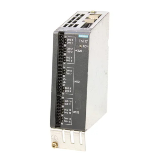
Description 1.2 Properties: TM15 / TM17 High Feature Properties: TM15 / TM17 High Feature Figure 1-3 Terminal Module TM15 and Terminal Module TM17 High Feature The properties of the Terminal Modules are presented below. This overview is intended to help you select the appropriate module for your application. Properties The TM15 and TM17 High Feature Terminal Modules are terminal expansion modules designed to be mounted on a DIN rail in accordance with DIN EN 50 022. - Page 14 Description 1.2 Properties: TM15 / TM17 High Feature The outputs are equipped with short-circuit protection, shutdown in case of overtemperature, and reverse-polarity protection. The actual signal state of each output channel can be read back on the SIMOTION side. The differences between the TM15 and TM17 High Feature Terminal Modules are defined by their range of application.
- Page 15 Description 1.2 Properties: TM15 / TM17 High Feature Table 1- 1 Comparison table for module selection Function TM15 TM15 DI/DO TM17 High Feature System integration Use only in conjunction with Use also in conjunction with Use only in conjunction with SIMOTION (SIMOTION D, CU310/CU320 (without SIMOTION (SIMOTION D,...
-
Page 16: Machine Applications
Description 1.3 Machine applications Machine applications 1.3.1 Overview Many production machines require fast, precise detection of signals or exact switching of digital outputs. The measuring input and output cam feature of the TM15 and TM17 High Feature modules represents an optimal solution for a variety of industrial applications. Applications requiring fast, high-precision detection of signals include: ●... -
Page 17: Application Examples
Description 1.3 Machine applications 1.3.2 Application examples Edge processing In this example, the movement of boards through a machine is controlled by fixed guides and clamping brackets. The sides of the boards are machined as they pass by a group of actuated cutters. - Page 18 Description 1.3 Machine applications Application of glue tracks In the following example, glue tracks are applied to a workpiece. Each track controls one glue gun via a digital output. Figure 1-5 Example: Electronic output cam control The glue guns are activated via outputs of an output cam based on the axis position. The axis position is measured by an encoder that connects an SMC encoder interface to SIMOTION D via DRIVE-CLiQ.
-
Page 19: Configuration/Programming
Configuration/programming Requirement To begin using the terminal modules, you need the following: Hardware requirements ● TM15 or TM17 High Feature ● One of the following components: – SIMOTION D (TM is connected directly to SIMOTION D or CX32) – SIMOTION D (TM is connected to a Control Unit, which is connected via PROFIBUS/PROFINET to SIMOTION D) –... -
Page 20: Configuring And Programming Tm1X Modules
Configuration/programming 2.2 Configuring and programming TM1x modules Configuring and programming TM1x modules Requirement Once the terminal module hardware is mechanically and electrically installed, it must be integrated in the application project using the SCOUT engineering software. The procedures contained in this chapter assume that the user has a general understanding of SCOUT. -
Page 21: Inserting New Tm1X Modules
Configuration/programming 2.2 Configuring and programming TM1x modules 2.2.1 Inserting new TM1x modules Procedure 1. Click the "+" next to "Input/output component". An expanded project tree similar to the one below will be displayed. Figure 2-1 "Insert input/output component" window 2. Double click "Insert input/output component". A window similar to the one shown below will appear. -
Page 22: Configuring I/O Channels - Tm15
Configuration/programming 2.2 Configuring and programming TM1x modules The "Name" field may be used to give the module a unique name (e.g. TM15_1). A drop- down list box containing the various module types will be displayed under Operating type. – TM15 (SIMOTION) for digital inputs/outputs as well as inputs of measuring inputs and outputs of output cams –... - Page 23 Configuration/programming 2.2 Configuring and programming TM1x modules Table 2- 1 Function of the buttons Button Function Configuration of I/O channels Display of component overview Display of DRIVE CLiQ topology When you click this button (available online only), the selected module can be identified by its RDY LED, which will flash (red-green).
- Page 24 Configuration/programming 2.2 Configuring and programming TM1x modules Table 2- 2 "Function" column: Options in the drop-down menu Menu option Description Channel used as a digital input DO (standard output Channel used as: - Digital output, or - Output of the output cam (without high switching accuracy) Measuring input Channel used as an input of a measuring input Output cam (fast output...
-
Page 25: Configuring I/O Channels - Tm17 High Feature
Configuration/programming 2.2 Configuring and programming TM1x modules 2.2.3 Configuring I/O channels – TM17 High Feature To begin configuring the TM17 High Feature Terminal Module, you can follow the procedure described in the chapter on "Configuring I/O Channels – TM15". The window shown below will open. - Page 26 Configuration/programming 2.2 Configuring and programming TM1x modules Measurement modes You can select the measurement mode from the dropdown menu in the "Mode" column. Table 2- 4 "Mode" column: Description of symbols Symbol Measurement mode Single measurement Cyclic measurement The main difference between the Single Measurement and Cyclic Measurement modes is that with Single Measurement, a measurement job must be issued by the Measuring Input technology object for each measurement.
- Page 27 Configuration/programming 2.2 Configuring and programming TM1x modules Table 2- 5 Measuring functions in conjunction with TM15 and TM17 High Feature Single measurement Cyclic measurement Supported terminal modules TM15 and TM17 High Feature TM17 High Feature only Measurement operation Measurement job must be Measuring function need only issued for each measurement be activated once.
- Page 28 Configuration/programming 2.2 Configuring and programming TM1x modules Table 2- 6 "Enable" and "Function" columns: Description of symbols Symbol for enable signal selection Symbol for assigned input of enable Explanation signal (Enable column) (Function column) No enable input No enable signal and therefore no enable input selected.
-
Page 29: Other Information
Configuration/programming 2.2 Configuring and programming TM1x modules 2.2.4 Other information Note When parameters are reassigned for the I/O channels, the new parameters do not take effect until you restart (power on or hot restart) the SINAMICS or SIMOTION D device. Note Additional information and parameter setting options are available in the project tree next to "Configuration"... -
Page 30: Generating Message Frames And Tm1X Drive Objects
Configuration/programming 2.2 Configuring and programming TM1x modules 2.2.5 Generating message frames and TM1x drive objects The message frames are automatically generated (or updated if they previously existed) when you select the "Close" button in the graphical configuration screen form. Note Do not make any changes to the parameters in the Expert list, as these changes will not be automatically updated in the message frame and could therefore lead to errors. - Page 31 Configuration/programming 2.2 Configuring and programming TM1x modules 2. Note that the addresses have been assigned automatically. These addresses are the logical start addresses of the module in the message frame. You must later add the offset values from the graphical configuration screen form to these addresses if you want to determine the addresses for the individual I/O channels.
-
Page 32: Accessing Inputs And Outputs In A User Task
Configuration/programming 2.3 Accessing inputs and outputs in a user task Accessing inputs and outputs in a user task Note The terminal module must be powered up before it can be accessed via I/O access. Otherwise, an I/O access error will occur and the CPU will go to STOP mode. See also Power Up and Synchronization with the User Program (Page 37) 2.3.1... - Page 33 Configuration/programming 2.3 Accessing inputs and outputs in a user task Refer to the following figure for the offset in the example. Figure 2-8 SCOUT – graphical configuration screen form for the TM17 (SIMOTION) Input DI The base "I-address" of the TM17 High Feature is "288". Now add the offset of 3.0. For DI 0, the resulting address is "291.0".
-
Page 34: Controlling The Enable Signal
Configuration/programming 2.3 Accessing inputs and outputs in a user task 2.3.2 Controlling the enable signal If the enable signal has been selected for one of the channels on the TM17 High Feature terminal module, the user program can control this hardware function by writing values to the output address assigned to the channel for the enable signal. -
Page 35: Signal Status Of The Enable Signal
Configuration/programming 2.3 Accessing inputs and outputs in a user task 2.3.3 Signal status of the enable signal If required, the user program can read the signal state of the enable signal using the assigned input address. The binary value reflects the logic state for T Example In the example, DI 13 on the TM17 High Feature terminal module is used as the channel for the enable signal. -
Page 36: I/O Assignment To Technology Objects
Configuration/programming 2.4 I/O assignment to technology objects I/O assignment to technology objects Linking Technology Objects with Terminal Modules Inputs of measuring inputs and outputs of output cams are operated with the associated technology objects (TOs). A general understanding of the use of technology objects is therefore needed to perform the desired configurations. -
Page 37: Power Up And Synchronization With The User Program
Configuration/programming 2.5 Power Up and Synchronization with the User Program Power Up and Synchronization with the User Program An isochronous bus is required for operation of the TM1x terminal modules. The terminal modules must have powered up and reached the synchronized state before they can be read- or write-accessed. -
Page 38: Monitoring Synchronization By Direct Access To The Module Status Word
Configuration/programming 2.5 Power Up and Synchronization with the User Program The TaskStartInfo contains the logical address of the relevant module. TSI#logDiagAdr, TSI#details, TSI#eventClass, and TSI#faultId are irrelevant for TM15/TM17 High Feature Terminal Modules. For additional information on the TaskStartInfo, refer to the "SIMOTION ST Structured Text" Manual. -
Page 39: Export/Import Project
Configuration/programming 2.6 Export/import project Export/import project A consistent project, which uses TM15 or TM17 High Feature Modules, can be consistently exported and reimported via Project Export/Import. If only the SIMOTION CPU is exported, the message frame configuration for TM1x is not exported with it. -
Page 40: Limitations Of Use
Configuration/programming 2.7 Limitations of use Limitations of use Overview The maximum possible number of terminal modules per SIMOTION D, SINAMICS Control Unit or CX32 depends on the following factors: ● Maximum number of terminal modules ● Maximum number of drive objects ●... -
Page 41: Maximum Number Of Drive Objects
Configuration/programming 2.7 Limitations of use If the TM15 or TM17 High Feature Terminal Module is operated on a DRIVE CLiQ line with a cycle time less than 125 µs, communication with these modules is not possible. Note Exceeding the allowable number of Terminal Modules on a given DRIVE CLiQ line can cause the DRIVE CLiQ interface to cease communication. -
Page 42: Maximum Permissible Message Frame Length
● Message frame length for all axis message frames (e.g.: Standard message frame 5 has "PZD 9/9" → 9 words [18 bytes] in each direction) ● Message frame length for all Line Modules (e.g.: SIEMENS telegram 370 for infeed with PZD 1/1 → 1 word [2 bytes] in each direction) ●... -
Page 43: Consistency Checks
Configuration/programming 2.7 Limitations of use 2.7.4 Consistency checks To ensure that applicable restrictions are not violated, SCOUT has the following built-in consistency checks: ● At any time, from the SCOUT main menu, "Check consistency" can be selected from the "Project" drop-down menu. (For more information, refer to the SCOUT online help.) This allows you to verify that the programmed configuration is consistent with the defined hardware configuration. -
Page 45: Commissioning
Commissioning Power-up Once the terminal module is physically installed and connected electrically, power may be applied to the unit. DANGER Ensure that installation and operation are in accordance with the instructions provided in this Manual, and in accordance with the Safety Guidelines provided at the beginning of this Manual. -
Page 46: Updating The Firmware
Commissioning 3.2 Updating the firmware Updating the firmware The module firmware can be updated using a CompactFlash Card, which is inserted in the SIMOTION D or SINAMICS S120 Control Unit. Procedure 1. Online connection for SCOUT In the project tree, click "SINAMICS_Integrated". Go online by clicking the "Connect to target system"... - Page 47 Commissioning 3.2 Updating the firmware 3. Updating the firmware Right-click the "Firmware Update button". A window will open (similar to screen below). Figure 3-3 Firmware update You can now select either "Select all" or an individual component in the "FW Update" column;...
-
Page 48: Synchronous Mode
Commissioning 3.3 Synchronous mode Synchronous mode Note This chapter pertains only to systems with external drives since this type of drive must be synchronized during configuration of PROFIBUS/PROFINET. Conversely, systems with integrated drives (i.e., one using SIMOTION D or CX32) use an integrated PROFIBUS that is pre-configured and synchronized. - Page 49 Commissioning 3.3 Synchronous mode See also Error messages (Page 51) Power Up and Synchronization with the User Program (Page 37) PROFINET procedure The basic procedure with PROFINET corresponds to PROFIBUS. However, you must enable synchronization in the properties of the device's PROFINET interface module on the "Application"...
-
Page 51: Error Messages
Error messages Introduction The error messages generated by the TM15 or TM17 High Feature modules are reported cyclically to the SIMOTION Motion Control System via the module status word as well as the diagnostic interrupt. The input address of the status word is identical to the start address (I- address) of the module. - Page 52 Error messages Errors cannot be acknowledged. The error message is automatically deleted as soon as the device has been restarted or the cause of error has been corrected. Note The user program must always use a WORD variable to access the status word (individual bits must be isolated by masking).
- Page 53 Error messages Error codes Table 4- 1 Error codes (for hotline) ERROR CODE 35... BITS DESCRIPTION REMEDY ...801 to Internal module error Replace the module ...905 and contact your local technical support. communication problem on DRIVE CLiQ interface ...906 At least one of the Check all terminals for terminals for the I/O the I/O power supply.
- Page 54 Error messages Error correction If problems arise during commissioning of the TM15 or TM17 High Feature, please verify the following: ● Make sure that the planned application is permitted. Note the information in the SIMOTION constraint list (see SCOUT CD). ●...
-
Page 55: Application Tips
Application tips Tips on proximity switches Proximity switches can be used in conjunction with the terminal modules to sense the presence or absence of a metallic surface. The advantages of using proximity switches over mechanical switches include the ability to perform non-contact sensing and a longer switch life. -
Page 56: Proximity Switch Cable Shielding
Application tips 5.1 Tips on proximity switches 5.1.1 Proximity switch cable shielding The proximity switch shield should be grounded to the metal case on the switch side and to the shield connection on the terminal module at the other end. This grounding to the machine frame should be made in such a way that it will not corrode. -
Page 57: Information On Leakage Currents
Application tips 5.2 Information on leakage currents Information on leakage currents 5.2.1 Input configuration Terminal module inputs occasionally receive their signal from an electronic device. Such a device can produce leakage current when the device is in de-energized state (OFF). If this current causes the input voltage at the terminal module to exceed 5 Volts, the circuit may not be able to detect whether this device is switched on or off. -
Page 58: Power Switches ("Smartfets")
Application tips 5.3 Power switches ("SmartFETs") Power switches ("SmartFETs") The power switches used for outputs have built-in protection from excessive load currents and short circuits at the output. The hardware of the module monitors the overcurrent/over temperature signal. Note If the power switch is switched OFF due to an over temperature or overcurrent condition but the "ON"... -
Page 59: Input And Output Circuit
Application tips 5.4 Input and output circuit Input and output circuit TM15 Figure 5-2 Input and output circuit - TM15 Grounding scheme For TM15, the following are internally connected: ● Module power supply ground ● Logic ground ● TM chassis The ground for the I/O power supply (terminals M1, M2, and M3) is capacitively coupled to the three grounds indicated above. - Page 60 Application tips 5.4 Input and output circuit TM17 High Feature Figure 5-3 Input and output circuit - TM17 Grounding scheme For TM17 High Feature, the following are internally connected: ● Module power supply ground ● Logic ground ● TM chassis The ground of the I/O power supply is connected directly to the three grounds indicated above.
-
Page 61: Other Application Examples
Application tips 5.5 Other application examples Other application examples 5.5.1 Use of inputs The following figure shows an example of an input connection. Although TM15 is shown, the TM17 High Feature is wired in a similar manner. Note that no 24 VDC is required on the "L1+"... -
Page 62: Use Of Outputs
Application tips 5.5 Other application examples 5.5.2 Use of outputs The following figure shows an example of an indicator lamp connection. Although the TM15 is shown, the TM17 High Feature can be wired in a similar manner. Please note that 24 VDC is required on the "L1+"... -
Page 63: Connection Of A Proximity Switch
Application tips 5.5 Other application examples 5.5.3 Connection of a proximity switch The following figure shows an example of a proximity switch connection. Several "M" (ground) terminals are available. In this example, the switch is supplied with 24 VDC via a DI/O (DI/O 2 in the example below). -
Page 64: Using The Enable Signal
Application tips 5.5 Other application examples 5.5.4 Using the enable signal This example illustrates the use of enable signals with outputs of output cams. When a workpiece is in the proper position, the output of the output cam is activated via the enable input. -
Page 65: Multiple Μs-Granular Measuring Ranges
Application tips 5.5 Other application examples 5.5.5 Multiple µs-granular measuring ranges A maximum of one measuring range can be specified for the Measuring Input technology object. Only measurements taken within this range are recorded. The resolution of the measuring range of the Measuring Input technology object conforms to the measuring input processing cycle clock (IPO interpolator cycle clock, IPO2 interpolator cycle clock, or position control cycle clock). -
Page 66: Acquisition Of Times / Time-Triggered Output
Application tips 5.5 Other application examples Figure 5-8 Multiple µs-granular measuring ranges 5.5.6 Acquisition of times / time-triggered output If it is necessary to acquire times (e.g., measure the duration of a pulse) or to output a signal for a specific time period (e.g., output a pulse for a certain duration), a Measuring Input technology object or an Output Cam / Output Cam Track technology object connection to a virtual axis can be used for this purpose. -
Page 67: Frequently Asked Questions (Faqs)
Application tips 5.6 Frequently Asked Questions (FAQs) Frequently Asked Questions (FAQs) Current FAQs on the Terminal Modules TM15 and TM17 High Feature are located at the following link: http://support.automation.siemens.com/WW/view/de/24332926 TM15 / TM17 High Feature Operating Manual Commissioning Manual, 05/2009... -
Page 69: Technical Data
Technical data Operating modes 6.1.1 Overview of operating modes Each channel can be individually configured for one of the following modes: Table 6- 1 Operating modes Mode of operation TM15 TM17 High Feature Digital input (DI) Input of measuring input (single measurement) Input of measuring input (cyclic measurement) -
Page 70: Input Modes
Technical data 6.1 Operating modes 6.1.2 Input modes Digital input (TM15/TM17 High Feature) If an I/O channel has been configured as a DI, it operates as a standard digital input. Input of measuring input (TM15/TM17 High Feature) If an I/O channel has been configured as an input of a measuring input, a time value is acquired with the input edge. - Page 71 Technical data 6.1 Operating modes Table 6- 2 Timing for input of measuring input Timer TM15 TM17 High Feature Comments 125 µs 1 µs Resolution ≥ 125 µs ≥ 1 µs/125 µs TM17: Depends on selected filter times ≥ 125 µs ≥...
-
Page 72: Output Modes
Technical data 6.1 Operating modes 6.1.3 Output modes Digital output (TM15/TM17 High Feature) If a channel has been configured as a DO, it operates as a standard digital output. See figure under "System behavior for digital inputs and outputs" Output of output cam (TM15/TM17 High Feature) This operating mode treats output channels as outputs of an output cam (see section on "System Behavior"). - Page 73 Technical data 6.1 Operating modes Level-triggered enable With a level-triggered enable, output cams are only output to the output if the enable signal is applied statically before the output cam start. If the enable signal is retracted before the output cam end, the output cam is still output up to the end.
- Page 74 Technical data 6.1 Operating modes Edge-triggered enable With an edge-triggered enable, output cams are output at the output only if the enable status exists before the output cam start. The enable status is controlled by a configured Measuring Input Technology Object. For the Measuring Input TO, only the "one-time measuring"...
- Page 75 Technical data 6.1 Operating modes The enable status can be monitored via the I/O area of the enable input. If the enable status is retracted before the output cam ends, the output cam is still output until the end if it has already started. New output cams are no longer output. Figure 6-3 Diagram - Output of output cam with edge-triggered enable signal Note...
-
Page 76: System Behavior
Technical data 6.2 System behavior System behavior The following timing data relate to a clock cycle setting of IPO: Servo: Bus cycle clock = 1 : 1 : 1 and a scan routine in the IPO synchronous task. Note The following describes the system behavior for PROFIBUS and can also, in principle, lay the basis for PROFINET configurations. - Page 77 Technical data 6.2 System behavior + 1 x DRIVE CLiQ cycle; SINAMICS: T ≥ 125 µs + 1 x DRIVE CLiQ cycle SINAMICS: T ≥ 125 µs where T and T are isochronous PROFIBUS time parameters. The value of T and T depends on the other PROFIBUS nodes;...
-
Page 78: System Timing For Single Measurement
Technical data 6.2 System behavior 6.2.2 System timing for single measurement The system behavior for a single measurement is shown in the figure below: Figure 6-6 System behavior for single measurement (call Measuring Input technology object and user program in the IPO cycle clock) If a measuring input event occurs in the shaded area in IPO cycle clock #1, then the actual event time T is transferred at the beginning of the following IPO cycle clock. -
Page 79: System Behavior With Cyclic Measurement
Technical data 6.2 System behavior The minimum pulse width depends on the specified edge selection: Edge selection Minimum distance Explanation Rising edge Minimum sampling cycle Each new edge requires a new measurement command. (see "Minimum Sampling Cycle" table). Falling edge Both edges >1 µs/125 µs (TM17) - Page 80 Technical data 6.2 System behavior Figure 6-7 System behavior with cyclic measurement (call TO Measuring Input and user program in the IPO cycle clock) Note If no edges are measured in a clock cycle, the TM17 High Feature can measure up to 4 edges in the following clock cycle, whereby the 3rd and, if necessary, 4th edges are buffered (buffer of up to 2 edges).
-
Page 81: System Behavior With Outputs Of Output Cam
Technical data 6.2 System behavior 6.2.4 System behavior with outputs of output cam The system behavior for outputs of output cam is shown in the figure below: Figure 6-8 System behavior with outputs of output cams (call TO Output Cam and user program in the IPO cycle clock) In order to switch an output of an output cam in the shaded area of IPO #3, the Output Cam technology object (TO) determines the switching positions in IPO #1. -
Page 82: Message Frames
Technical data 6.3 Message frames Message frames The maximum length of either the setpoint message frame or the actual value message frame is ● With integrated drives (SIMOTION D/CX32): 512 bytes ● With external drives (CU320/CU310): – On PROFIBUS DP: 244 bytes –... - Page 83 Technical data 6.3 Message frames Example: Assume a TM17 High Feature is configured with: ● 4 inputs of measuring inputs ● 6 outputs of output cams ● 3 digital inputs ● 3 digital outputs The following applies: ● Length of setpoint message frame (output address area) = 8 + 4 ·...
-
Page 85: Version Overview
Version overview Version overview Function Available as of TM15/TM17 High Feature Use of TM15 and TM17 High Feature with SIMOTION D4x5 or on Since delivery release a SINAMICS S120 Control Unit CU320, which is connected via (SIMOTION V3.1.1, SINAMICS PROFIBUS DP to SIMOTION C, P, or D V2.1) TM15 and TM17 High Feature with CX32 SIMOTION V3.2, SP1... - Page 86 Version overview 7.1 Version overview Function Available as of Axis types (servo/vector) Use of TM15 and TM17 High Feature in conjunction with servo Since delivery release axes (SIMOTION V3.1.1, SINAMICS V2.1) Use of TM15 and TM17 High Feature in conjunction with vector SIMOTION V4.1, SP1 axes SINAMICS V2.5...
- Page 87 Version overview 7.1 Version overview Note The SIMOTION version information always refers to the use of the respective SIMOTION SCOUT version, the SIMOTION runtime version as well as the corresponding version of the "CAM" or "CAM_EXT" technology package (including Measuring Input, Output Cam and Cam Track technology objects).
-
Page 89: Ec Declaration Of Conformity
EC Declaration of Conformity EC Declaration of Conformity The Declaration of Conformity can be found on the following website: http://support.automation.siemens.com/WW/view/de/15257461 TM15 / TM17 High Feature Operating Manual Commissioning Manual, 05/2009... -
Page 91: Esd Guidelines
ESD guidelines ESD definition What does ESD stand for? All electronic modules are equipped with large-scale integrated ICs or components. Because of the technology used, these electronic components are very sensitive to overvoltages and thus to electrostatic discharge. These Electrostatic Sensitive Devices/Modules are commonly abbreviated ESD. The ESD designation is used internationally to refer to electrostatic sensitive devices. -
Page 92: Electrostatic Charging Of Individuals
ESD guidelines B.2 Electrostatic charging of individuals Electrostatic charging of individuals Any person who is not conductively connected to the electrical potential of the environment can accumulate an electrostatic charge. The following figure indicates the maximum electrostatic charges that can accumulate in a person who is operating equipment when he comes into contact with the materials shown in the figure. -
Page 93: List Of Abbreviations
List of abbreviations Refer to this list for an understanding of the abbreviations and acronyms that are used in this Manual: BiCo Binector/Connector Control unit Digital input DI/O Digital input/output Digital output Input/output FPGA Field programmable gate array Interpolator cycle clock Load power supply Ground Reference ground... -
Page 95: Index
Index Cyclic measurement Configuration, 26 Timing, 79 Abbreviations, 93 Access to I/O channels, 32 Addresses Logical start address, 31 Declaration of conformity, 89 Offset, 24 Address, 33 Alignment HW Config, 30 Example of input circuitry, 61 Application Examples, 17 Operating mode, 70 Diagnostic Interrupt, 52 Address, 33 Example of output circuitry, 62... - Page 96 Index FAQs, 67 Number Fields of application Maximum number of Terminal Modules, 40 TM15/TM17 High Feature, 16 Number of edges for measurement modes, 26 Filter selection for TM17 High Feature, 25 Firmware update, 46 Offset, 24 Output of output cam Hardware requirements, 19 Accuracy, 15 HW Config...
- Page 97 Index SIMOTION D Properties, 13 Max. number of modules, 40 Structure, 12 SINAMICS 120 TM17 High Feature CU310/CU320, 10 Circuit, 60 Single measurement Function overview, 15 Configuration, 26 Servo drives, 29 Timing, 78 Vector drives, 29 Software requirements, 19 State Booting, 38 Errors, 51 Updating firmware, 46...
- Page 98 SIMOTION SIMOTION SCOUT TM15 / TM17 High Feature Operating Manual Commissioning Manual, 05/2009...
- Page 99 SIMOTION SIMOTION SCOUT TM15 / TM17 High Feature Operating Manual Commissioning Manual, 05/2009...