Advertisement
Quick Links
WARNING: Disconnect all power from the starter and
overload relay before installing, modifying, or servicing.
A VERTISSEMENT:
installation, modification, ou entretien.
CAUTION: Before installing this product in a nuclear
application, determine if it is intended for such use.
ATTENTION: Avant d'installer le produit dans une
application nucleaire, verifier si cela est permis.
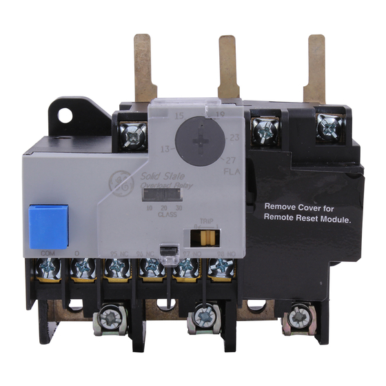
The ABB Solid State Overload Relay is shown in Figure
1. The catalog numbers and electrical specifications
are listed in Table 1.
The following instructions describe the installation of a
Solid State Overload Relay as a replacement for an
existing overload relay on a 300-Line starter.
Disconnect all sources of power to the starter.
2 . Disconnect all control and power wiring from the
load side of the existing overload relay.
3. Loosen, but do not remove, the power terminal
screws located between the top of the overload
relay and the contactor.
Remove and save the overload relay mounting
screw, located at the bottom right corner of the
overload relay housing.
CR324CXCS
CR324CXCP
CR324CXDS
CR324CXDP
CR324CXES
CR324CXEP
CR324CXFP
C:R324CXFS
CR324CXGS
CR324CXGP
CR324CXHS
CR324CXHP
CR324DXGP
CR324DXGS
CR324DXHS
CR324DXHP
CR324DXJS
CR324DXJP
GEH-6430 User's Guide
Solid State Overload Relay
NEMA Sizes 0, 1 & 2
Introduction
Replacement Installation
1.
4.
Catalog Number
Starter Mount
Panel Mount
NOTE: Maximum fuse and breaker sizes are intended as guidelines. Refer to NEC and local codes for proper fuse and breaker selection.
*Size O not to exceed 18 amperes.
Table 1. Solid State Overload Relay, NEMA Sizes 0, 1
Couper
l' alimen tation
0&l
.4-.85
0&1
.8-1.7
0&1
1.6-3.4
0 & 1
3.2-6.8
0&l
6.5-13.5
0 & 1
13-27 *
2
6.5-13.5
2
13-27
2
25-50
Current
NEMA
Range,
Size
amps
2, catalog numbers and electrical specifications.
&
avant
5. Remove the overload relay from the starter
baseplate.
6. Place the Solid State Overload Relay on the starter
baseplate and secure it with the mounting screw.
7. Torque the power terminal screws, between the
top of the Solid State Overload Relay and the
contactor, to 20 lb-in to complete the electrical
connections.
8. Connect the control and power wiring to the
terminals on the load side of the Solid State
Overload Relay, shown in Figure 2.
9. Reconnect power sources to the starter.
10. Fully depress the blue reset button on the Solid
State Overload Relay to insure that it is in the reset
position. The yellow trip flag will be at its right
position, as illustrated in Figure 2.
14-8
14-8
14-8
14-8
14-8
14-8
18-4
18-4
18-4
Figure 1. Solid State Overload Relay (size 1 shown).
Wire Size
Max Fuse Size, Max Breaker
°
(75
C, Cu
amps ( Class T,
only) AWG #
H,J, L, R, K)
3
15
6
15
10
15
2 5
25
50
50
100
100
50
50
100
100
200
200
Ratings,
amps
CR306B/C
CR306B/C
CR306B/C
CR306B/C
CR306B/C
CR306B/C
CR306D
CR306D
CR306D
Use with
ABB
Contactor
Advertisement

Related Manuals for ABB CR324CXCS


Summary of Contents for ABB CR324CXCS
- Page 1 ATTENTION: Avant d'installer le produit dans une application nucleaire, verifier si cela est permis. The ABB Solid State Overload Relay is shown in Figure 1. The catalog numbers and electrical specifications are listed in Table 1.
- Page 2 CAUTION: The slide switch must be in one of the three ATTENTION: Le bouton de selection de la classe de detent positions. If the slide is between one of the detents, the default is protection class 30. protection doit etre dans une des trois positions stables. Si le bouton se trouve entre deux positions, la classe de protection est fixee a 30 par default.
- Page 4 Should further info rmation be desired or should particular problems arise that are not covered sufficiently for the purchaser's purposes, the matter should be referred to your local ABB Sales Office. —...