Table of Contents
Advertisement
Quick Links
LMV60.110A2
Burner management system for forced draft burners with the
main functions:
Burner control
Fuel-air ratio control
Installation Guide
CC1J7560en
4/21/2020
The LMV6 and this Installation Guide are intended for original equipment
manufacturers (OEMs) using the LMV6 in or on their products.
Please note!
All the safety, warning, and technical notes given in the basic documentation
for the LMV6 (P7560) also apply to this document in full. Failure to observe this
poses a risk of damaging the safety functions and the risk of electric shock.
Smart Infrastructure
Advertisement
Table of Contents

Related Manuals for Siemens LMV60.110A2


Summary of Contents for Siemens LMV60.110A2
- Page 1 LMV60.110A2 Burner management system for forced draft burners with the main functions: Burner control Fuel-air ratio control Installation Guide The LMV6 and this Installation Guide are intended for original equipment manufacturers (OEMs) using the LMV6 in or on their products.
- Page 2 Supplementary documentation Product type Designation Documentation type Documentation number LMV60.110A2 Burner management system User Documentation A7560.1 LMV6 Burner management system Environmental Declaration E7560 *) LMV60.110A2 Burner management system Parameter list and error code list I7560 LMV60.110A2 Burner management system Data Sheet N7560 LMV60.110A2...
-
Page 3: Table Of Contents
Installation notes ................... 5 Electrical connection of the flame detectors ............ 6 Assignment of connections ................. 7 LMV60.110A2 ....................7 Protection classes ................... 8 2.2.1 LMV6 ....................... 8 2.2.2 AGG6.200 ...................... - Page 4 12.1 Parallel operation ................... 36 12.2 Variant for parallel operation ................37 List of figures ....................38 4/39 Smart Infrastructure LMV6 Installation Guide CC1J7560en 4/21/2020...
-
Page 5: Installation Notes
Installation notes Always run the high-voltage ignition cables separately from the LMV6 and other cables while observing the greatest possible distances Do not mix up phase and neutral (midpoint) conductors Install switches, fuses, and grounding in accordance with local regulations ... -
Page 6: Electrical Connection Of The Flame Detectors
Electrical connection of the flame detectors It is important to achieve practically disturbance-free and loss-free signal transmission: Never run the detector cable together with other cables – Line capacitance reduces the magnitude of the flame signal – Use a separate cable ... -
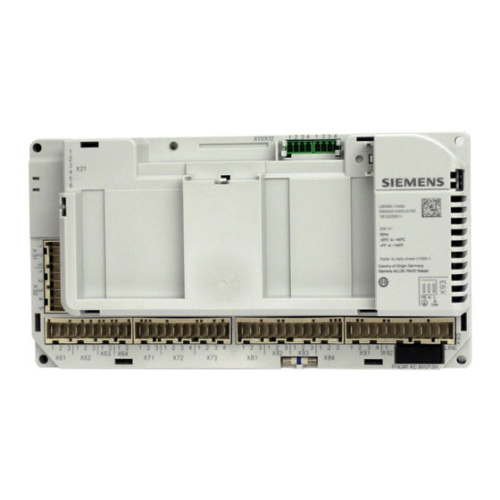
Page 7: Assignment Of Connections
Assignment of connections LMV60.110A2 Figure 1: LMV60.110A2 connection assignment 7/39 Smart Infrastructure LMV6 Installation Guide CC1J7560en 2 Assignment of connections 4/21/2020... -
Page 8: Protection Classes
Protection classes 2.2.1 LMV6 Figure 2: LMV6 protection classes Please note! Degree of protection IP40! The LMV6 offers degree of protection IP00. The burner or boiler manufacturer must ensure degree of protection IP40 for the LMV6 in accordance with DIN EN 60529 through adequate installation. 8/39 Smart Infrastructure LMV6 Installation Guide... -
Page 9: Agg6.200
2.2.2 AGG6.200 Figure 3: AGG6.200 protection classes Please note! Degree of protection IP40! The AGG6.200 offers degree of protection IP00. The burner or boiler manufacturer must ensure degree of protection IP40 for the AGG6.200 in accordance with DIN EN 60529 through adequate installation. 9/39 Smart Infrastructure LMV6 Installation Guide... -
Page 10: Description Of The Terminals
Description of the terminals Note! AGG9 connector sets! The AGG9 connectors of the connecting cables for the LMV6 may only be removed or replaced when the plant is shut down (all-pole disconnection)! Terminal Terminal markings on LMV6 housing Coding Plug-in space coding Type (ASN) Product designation for 200 packaging units... -
Page 11: Terminal X51 / X52
3.1.2 Terminal X51 / X52 1 2 3 1 2 3 4 5 Figure 5: Description of terminals X51 / X52 Flame supervision with QRA2 / QRA4 / QRA10 Type Terminal Coding Input Output Function Electrical limit value Parameter (ASN) 03K80 ●... -
Page 12: Terminal X61 / X62 / X63 / X64
3.1.3 Terminal X61 / X62 / X63 / X64 1 2 3 1 2 3 Figure 6: Description of terminal X61 / X62 / X63 / X64 Type Terminal Coding Input Output Function Electrical limit value Parameter (ASN) Protective earth (PE) 230 V~ +10% / -15% 50 Hz ●... -
Page 13: Terminal X71 / X72 / X73
3.1.4 Terminal X71 / X72 / X73 1 2 3 1 2 3 4 1 2 3 4 Figure 7: Description of terminal X71 / X72 / X73 Type Terminal Coding Input Output Function Electrical limit value Parameter (ASN) ● 03K48 ●... -
Page 14: Terminal X81 / X82 / X83 / X84
3.1.5 Terminal X81 / X82 / X83 / X84 1 2 3 1 2 3 1 2 3 1 2 3 Figure 8: Description of terminal X81 / X82 / X83 / X84 Type Terminal Coding Input Output Function Electrical limit value Parameter (ASN) Protective earth (PE) -
Page 15: Terminal X91 / X92 / X93
3.1.6 Terminal X91 / X92 / X93 1 2 3 4 1 LINE Figure 9: Description of terminal X91 / X92 / X93 Type Terminal Coding Input Output Function Electrical limit value Parameter (ASN) Protective earth (PE) Neutral conductor (N) Auxiliary terminal X91 *) 04K77... - Page 16 Caution! Terminal X92 pin 1! Make sure that the voltage output on terminal X92 pin 1 is not connected to live parts. The terminal must not be connected. Failure to observe this information poses a risk of the safety functions being impaired. Caution! Terminal X92 pin 3! Only a simple button may be connected to terminal X92 pin 3.
-
Page 17: Agg6.200A5
3.2 AGG6.200A5 3.2.1 Terminal X13 Figure 10: Description of terminal X13 Type Terminal Coding Input Output Function Electrical limit value Parameter (ASN) DC power supply for the system Approx. 24 V DC ● components (24 V DC) max. 1.25 A DC U ↔... -
Page 18: Block Diagram Inputs / Outputs
Block diagram inputs / outputs Figure 12: Block diagram inputs / outputs 18/39 Smart Infrastructure LMV6 Installation Guide CC1J7560en 4 Block diagram inputs / outputs 4/21/2020... -
Page 19: Azl66 Connection Assignment
AZL66 connection assignment Figure 13: AZL66 connection assignment SQM4 connection assignment Figure 14: SQM4 connection assignment 19/39 Smart Infrastructure LMV6 Installation Guide CC1J7560en 5 AZL66 connection assignment 4/21/2020... -
Page 20: Agg6.200A5 Connection Assignment
AGG6.200A5 connection assignment Figure 15: AGG6.200A5 connection assignment 20/39 Smart Infrastructure LMV6 Installation Guide CC1J7560en 7 AGG6.200A5 connection assignment 4/21/2020... -
Page 21: Earthing And Shielding Of The Lmv6
Earthing and shielding of the LMV6 8.1 Earthing The LMV6 has 2 different types of earthing: Protective earth PE Functional earth FE 8.1.1 Protective earth (PE) The protective earth (PE) of the LMV6 must be connected. The purpose of protective earth (PE) is to provide a protective conductor connection for all connected units/components. -
Page 22: Functional Earth (Fe)
The connection between the functional earth (FE) and the housing of the SQM4 should also be established via short and low-resistance connections. Siemens recommends equipping the SQM4 with a separate cable if necessary. These cables should be connected to the functional earth (FE) with the greatest possible cross section (min. -
Page 23: Emc-Compliant Wiring
8.1.3 EMC-compliant wiring Shielded cables must also be used in control panels for the bus connections between the LMV6, SQM4, and AZL66 Each SQM4 connected to the LMV6 must be connected to the same functional earth (FE) or earthing point via a short cable or low-resistance housing connection as the LMV6 ... -
Page 24: Earthing And Wiring Of The Lmv6
8.1.4 Earthing and wiring of the LMV6 Figure 18: Earthing and wiring of the LMV6 24/39 Smart Infrastructure LMV6 Installation Guide CC1J7560en 8 Earthing and shielding of the LMV6 4/21/2020... - Page 25 No shielding on the AZL66. A screw connection can be established to prevent the connecting plug on the AZL66 from being pulled out. Connect the SQM4 housing with the functional earth (FE): The connection between the SQM4 housing and the functional earth (FE) can be established by means of a low-resistance connection using the fixing screws or by means of an additional cable connection.
- Page 26 Continued “Earthing and wiring of the LMV6” Electrical environment in which the cables run parallel: Wiring of the bus cables at LMV6 terminal X11 and X12. For all shielded cables that have to be earthed, the cable shield must be fixed by a shield clamp (e.g., Icotek) or the shield clamp provided on the AGG6.500.
-
Page 27: Earthing Systems
8.2 Earthing systems 8.2.1 TN earthing system In a TN earthing system, one of the points on the generator or transformer is connected to earth. In a three-phase system, this is typically the star point. TN−S earthing: Protective earth (PE) and neutral (N) are separate conductors. This system is currently used in most residential houses and commercial plants in North America and Europe. -
Page 28: Protective Earth (Pe) And Functional Earth (Fe)
8.3 Protective earth (PE) and functional earth (FE) Figure 21: Protective earth (PE), functional earth (FE) Protective Earth (PE): Protective earth (PE) is a device earthing conductor that avoids hazards by keeping the exposed conductive surfaces of a device at ground potential. To avoid a potential voltage drop, there should be no current flowing through this conductor under normal circumstances. -
Page 29: Ignition
Ignition The ignition is a further strong source of interference. For this reason, please observe the following recommendations: Keep the cable loop/length in the high-voltage ignition circuit as short as possible Use a special EMC-compliant ignition cable Avoid capacitive and inductive coupling to other signal lines. - Page 30 If a 1-pole ignition has to be used, it is very important to have a low impedance at the mechanical connections (transitions) of the burner housing (no insulation material, e.g., no paint). Only then will you get a good current flow from the ignition spark back to the ignition transformer, resulting in low EM emissions (EMC): Figure 24: 1-pole ignition with low impedance at the burner housing 30/39...
- Page 31 If the mechanical connections for the burner housing have a high level of impedance – e.g., due to paint – this causes multiple poor flows of current from the ignition spark back to the ignition transformer. These multiple current flows lead to high EM emissions (EMC).
-
Page 32: Wiring
10 Wiring Separate wiring is recommended for the following cables: Completely separate from all other cables High-voltage ignition cable – see also chapter Ignition Cable for the flame detectors Together in cable channel 1 for low voltage, e.g.: ... - Page 33 Figure 26: Example for wiring, earthing and shielding of the LMV6 33/39 Smart Infrastructure LMV6 Installation Guide CC1J7560en 10 Wiring 4/21/2020...
-
Page 34: Lmv6 Power Supply
11 LMV6 power supply General Power to the LMV6 is supplied via the internal power supply unit. This internal power supply unit supplies the internal assemblies, SQM4 and AZL66 via terminal X11/X12. Power to the bus users is supplied together with the communication lines in a common cable. -
Page 35: Cable Types
11.2 Cable types AGG6.641 (cable type 1) LMV6 system components Connection Color Wire cross-section in mm² 24 V DC White 1.25 CAN_H Yellow 0.25 CAN_L Green 0.25 Brown 1.25 Figure 28: AGG6.641 AGG6.635 (cable type 2) LMV6 AZL66 Connection Color Wire cross-section... -
Page 36: Commissioning
12 Commissioning 12.1 Parallel operation Figure 30: Parallel operation 36/39 Smart Infrastructure LMV6 Installation Guide CC1J7560en 12 Commissioning 4/21/2020... - Page 37 12.2 Variant for parallel operation Figure 31: Variant for parallel operation 37/39 Smart Infrastructure LMV6 Installation Guide CC1J7560en 12 Commissioning 4/21/2020...
- Page 38 13 List of figures Figure 1: LMV60.110A2 connection assignment ............7 Figure 2: LMV6 protection classes .................. 8 Figure 3: AGG6.200 protection classes ................9 Figure 4: Description of terminal X11 / X12 ..............10 Figure 5: Description of terminals X51 / X52 ..............11 ...
- Page 39 Siemens AG Smart Infrastructure © 2020 Siemens AG Smart Infrastructure Berliner Ring 23 Subject to change! 76437 Rastatt, Germany Tel. +49 (7222) 784 2396 www.siemens.com 39/39 Smart Infrastructure LMV6 Installation Guide CC1J7560en 13 List of figures 4/21/2020...